A short while ago I decided that I really needed a lathe in my life. I started looking at Chinese mini lathes which might have fitted in my workshop space, then late one night after a couple of beers I saw a lathe for sale on ebay with a starting bid of £75. I put a bid on to see what happened. What happened was no one else bid on it, this resulted in a trip to the outskirts of London to pick it up.
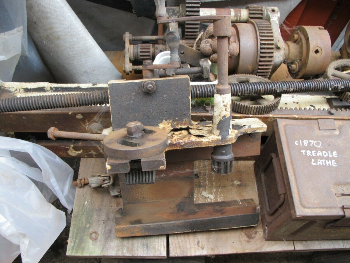
Below is the image of the lathe as advertised on eBay.

I was trying to judge the size of the lathe from the advert but totally misjudged. The bed is a two man lift and by the time the other parts were loaded the poor car went home squatting on its haunches.
Once home I got a chance to look at what I had. Everything was present but not in good shape. The white paint job had little to no adhesion to the metal which was fine as my intention is to strip and repaint it. The lead screw is seized and the drive gear on the end has missing teeth presumably due to it being seized. There is one set of gears to drive it but none of the rest of the set of change gears. This is not a problem as I intend to drive it electronically.
The tailstock was seized and took a bit of persuasion plus WD40 to free it up. I stripped it down oiled and repainted it. I was originally going to polish the hand wheel up but decided I like the patina it has developed.

The headstock had the backgears engaged which were also seized, once they were released the chuck rotates freely. Cleaning this up and painting it is further down the line. The crossslide is the next part that I'm cleaning up and painting. The crosslide was well oiled inside and came about easily. The toolpost is very basic and of its time at some point I will look at upgrading to something more useful.
Concurrent to the clean up I've started looking at powering the lathe. After lots of Internet searching I came across a series of videos using treadmill motors to convert lathes. As luck would have it a treadmill came up on eBay 2 miles from me. It was descibed as heavy again I was the only bidder. Once again I misjudged the size, when I went to pick it up it was too large to fit through the owners door on its own wheels and needed lifting. Another two man lift job, except I didn't have a second pair of hands. It took a crazy amount to lifting and shifting to get it out. Although it went in the car the rear hatch couldn't close. Very glad it was only two miles to drive.

Once home I stripped it down to the bits I needed. Which was mostly the drive motor and the secondary motor which raises the incline. The second motor I intend to use to drive the leadscrew. A lot of the online videos use the control board from the treadmill, but there are issues with this, firstly when you turn it on the speed ramps up slowly as a safety feature for the treadmill user, secondly you need to reset the speed each time you start it. This didn't work for me so I bought a selection of parts to build a control box. I luckily had an enclosure from an old job to put it all in. Below is the almost finished enclosure.

The treadmill came with an IEC lead which lead to an on off switch and thermal cut out all in a neat unit. I kept this and put it in the bottom of the enclosure.

This allows me to switch the whole unit on and off. Inside the power leads to an LED light transformer which steps the voltage down to 12v to drive the RPM readout and Hall Sensor.

The 240V line splits here and runs to an emergency stop start switch, from the stop start switch it runs to a unit which converts the 240AC to 240DC with a dial to control the motor speed. The output then feeds through a three position switch which allows me to run in forward or reverse.

Below is the list of parts I bought on eBay to put this together.
AC 220V Input Knob 20A PWM DC 220V Motor Speed Controller Regulator Switch
https://www.ebay.co.uk/itm/403156301841
4 Digital LED Blue Tachometer RPM Speed Meter+Hall Proximity Switch
4 Digital LED Blue Tachometer RPM Speed Meter+Hall Proximity Switc 981917618444 | eBay
Universal Replacement Switch 250V 15A NVR Switch Emergency Stop Switch
Universal Replacement Switch 250V 15A NVR Switch Emergency Stop Switch | eBay
LW26-/32A 3 Positions On-Off-On Changeover Selector Control Rotary Cam Switch
LW26-/32A 3 Positions On-Off-On Changeover Selector Control Rotary Cam Switch | eBay
The blurred taped off cables will lead to the drive motor via a flexible conduit.
The next stage will be to build a frame to hold the drive motor, I intend to use the drive belt that came with the motor to drive the spindle which moved the running surface. I will cut this spindle down to a shorter length and then run a belt from it to the lathe pulleys.


There will be further updates, but the next step is to build a new workshop once I have negotiated its location with my wife")
Below is the image of the lathe as advertised on eBay.
I was trying to judge the size of the lathe from the advert but totally misjudged. The bed is a two man lift and by the time the other parts were loaded the poor car went home squatting on its haunches.
Once home I got a chance to look at what I had. Everything was present but not in good shape. The white paint job had little to no adhesion to the metal which was fine as my intention is to strip and repaint it. The lead screw is seized and the drive gear on the end has missing teeth presumably due to it being seized. There is one set of gears to drive it but none of the rest of the set of change gears. This is not a problem as I intend to drive it electronically.
The tailstock was seized and took a bit of persuasion plus WD40 to free it up. I stripped it down oiled and repainted it. I was originally going to polish the hand wheel up but decided I like the patina it has developed.
The headstock had the backgears engaged which were also seized, once they were released the chuck rotates freely. Cleaning this up and painting it is further down the line. The crossslide is the next part that I'm cleaning up and painting. The crosslide was well oiled inside and came about easily. The toolpost is very basic and of its time at some point I will look at upgrading to something more useful.
Concurrent to the clean up I've started looking at powering the lathe. After lots of Internet searching I came across a series of videos using treadmill motors to convert lathes. As luck would have it a treadmill came up on eBay 2 miles from me. It was descibed as heavy again I was the only bidder. Once again I misjudged the size, when I went to pick it up it was too large to fit through the owners door on its own wheels and needed lifting. Another two man lift job, except I didn't have a second pair of hands. It took a crazy amount to lifting and shifting to get it out. Although it went in the car the rear hatch couldn't close. Very glad it was only two miles to drive.
Once home I stripped it down to the bits I needed. Which was mostly the drive motor and the secondary motor which raises the incline. The second motor I intend to use to drive the leadscrew. A lot of the online videos use the control board from the treadmill, but there are issues with this, firstly when you turn it on the speed ramps up slowly as a safety feature for the treadmill user, secondly you need to reset the speed each time you start it. This didn't work for me so I bought a selection of parts to build a control box. I luckily had an enclosure from an old job to put it all in. Below is the almost finished enclosure.
The treadmill came with an IEC lead which lead to an on off switch and thermal cut out all in a neat unit. I kept this and put it in the bottom of the enclosure.
This allows me to switch the whole unit on and off. Inside the power leads to an LED light transformer which steps the voltage down to 12v to drive the RPM readout and Hall Sensor.
The 240V line splits here and runs to an emergency stop start switch, from the stop start switch it runs to a unit which converts the 240AC to 240DC with a dial to control the motor speed. The output then feeds through a three position switch which allows me to run in forward or reverse.
Below is the list of parts I bought on eBay to put this together.
AC 220V Input Knob 20A PWM DC 220V Motor Speed Controller Regulator Switch
https://www.ebay.co.uk/itm/403156301841
4 Digital LED Blue Tachometer RPM Speed Meter+Hall Proximity Switch
4 Digital LED Blue Tachometer RPM Speed Meter+Hall Proximity Switc 981917618444 | eBay
Universal Replacement Switch 250V 15A NVR Switch Emergency Stop Switch
Universal Replacement Switch 250V 15A NVR Switch Emergency Stop Switch | eBay
LW26-/32A 3 Positions On-Off-On Changeover Selector Control Rotary Cam Switch
LW26-/32A 3 Positions On-Off-On Changeover Selector Control Rotary Cam Switch | eBay
The blurred taped off cables will lead to the drive motor via a flexible conduit.
The next stage will be to build a frame to hold the drive motor, I intend to use the drive belt that came with the motor to drive the spindle which moved the running surface. I will cut this spindle down to a shorter length and then run a belt from it to the lathe pulleys.
There will be further updates, but the next step is to build a new workshop once I have negotiated its location with my wife