Union Graduate rebuild

UKworkshop.co.uk

Help Support UKworkshop.co.uk:

This site may earn a commission from merchant affiliate links, including eBay, Amazon, and others.

TFrench

Established Member
Joined
6 Jul 2015
Messages
1,626
Reaction score
409
Location
Leics
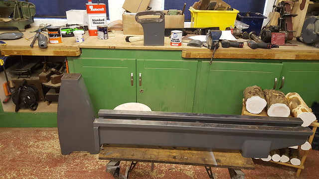
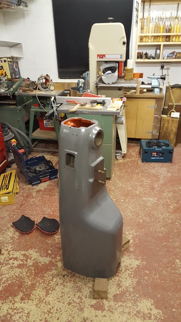
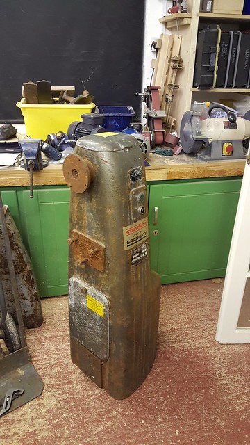
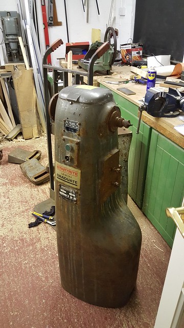
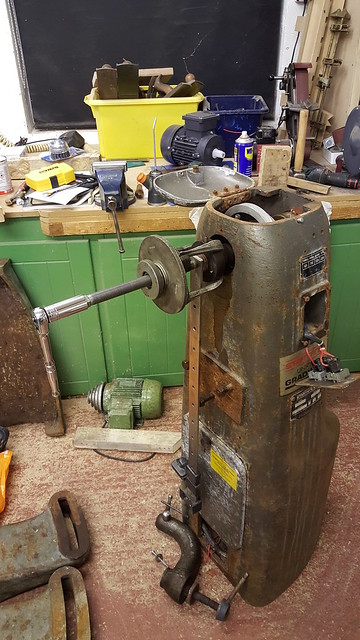
I've bought a slightly rough (read-very rough!) graduate on ebay to do up to be my "forever" lathe. It's big enough and heavy enough to tackle anything I'm going to want to do. It all started when the bearings gave up on my myford's motor. I bought a 3 phase motor and inverter to make it variable speed, then spotted this union lathe about 20 miles from me. Man maths prevailed and I decided I could better use the inverter and 3 phase motor in it rather than my myford.... Replaced the motor in the myford with a 240v one so I could continue turning while I got the big 'un running. It's not going to be up to the standards of one of wallace's wadkin resto's but it should look pretty when I'm done! So without further ado, here she is:
2016-11-06_10-43-59
20161103_184126

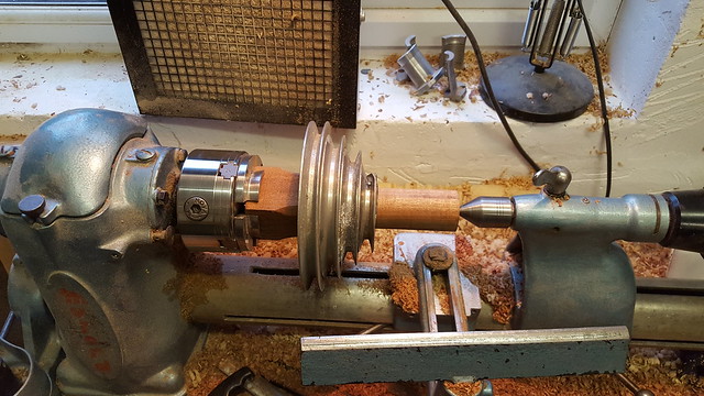
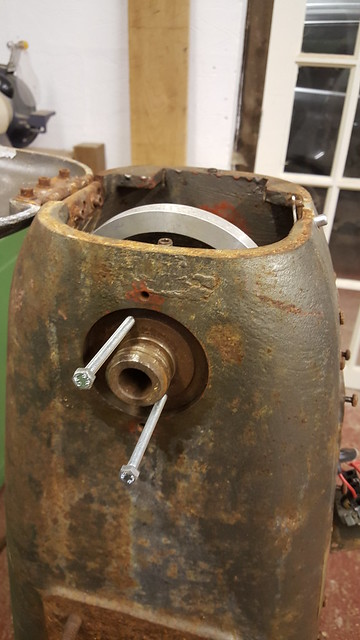
The Drive centre was firmly rusted in. Progressively bigger hammers took care of that. I then set about removing the spindle. After much lump hammer action, it was all moving apart from the outboard spacer. The one that holds it all in! I drilled and tapped the two existing holes in it to get a puller on it:
20161106_141934

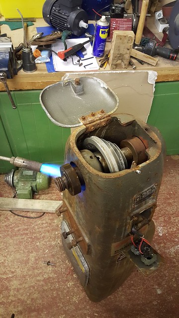
I got so much tension on it I was worried about stripping the threads. Called for reinforcements - dad with the propane gun! Tapped it all through from the inboard side so we could get heat directly on the offending part:
20161106_163437

Once it had cooled I could get a man sized puller on it!
20161106_211217

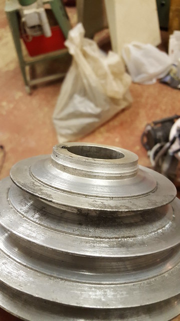
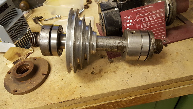
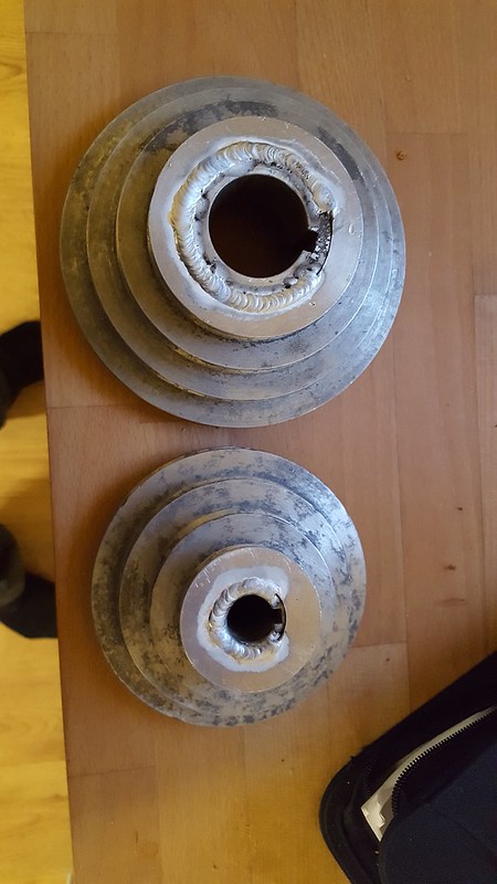
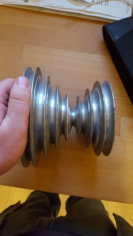
It still put up a fight but its off now. I've collected pretty much all the bits I need for it already, except the tailstock. One will turn up somewhere. The drive pulleys are both damaged but I can hopefully get them welded. The only other bit I seem to be missing is the turnbuckle arrangement that tensions the motor. I'm sure I can fabricate something for that though if I can get some measurements.
 
As they were made primarily for the education market, a common criticism is that the centres are too low. Now would be a good time to think about some sort of sub frame to raise it so it can be finished and painted as one? It could be a tidier end job.
 
I did a craft summer school in 1966 that included turning a bowl on one of those. Absolutely loved it. I always had it in the back of my mind to take it up again when I retired and here I am 50 years later, a widower with all the little birdies flown the nest, just me and the cat - happy as a clam at my long postponed hobby!

Good luck with the restoration - I'm sure many of us will be following your progress with interest.
 
I've seen quite a few raised up on bits of RSJ Phil - it hadn't occured to me it's because they're for schools. Is there a rule of thumb for what height the centres should be at?
 
Phil's right, I had a go on one and it felt much too low, rule of thumb is centres at elbow height
 
I was lucky enough to get one in decent condition, no bed, just a bowl lathe, but it was very affordable and included a disc sander and 14" faceplate. I was so pleased that I called myself Graduate_owner when I joined the forum. One thing I really like - apart from build quality and sheer weight - is the inboard and outboard threads are both 1 1/2" ( but outboard is left hand thread) which means one chuck with dual threads will fit both sides. My ML8 has different threads, so does my new ( new to me, that is) Viceroy, which is a bit of a pita. However I do like my Viceroy as well, and it has a full length bed.
Good luck with the refurb. Did you know there is a handbook on line? No need to pay for one.

K
 
The accepted correct height is when the tail centre is ideally placed to inflict serious pain on the end of the elbow the one time you bring your elbow hard back on it. From there on in you don't need to leave the centre in when it's not in use. :D
 
I've had a look and the centers are only about 2" below my elbow. My myford is 4-5" below, no wonder I get a sore back after a bit! I think I'll run it for a bit and see how I get on - knocking up a box section plinth will be easy enough and I've got an engine crane I can lift it with even when its assembled. I'll make a stencil of the base so I can get the hole centres if I ever do want to raise it!
 
phil.p":rzg1zxli said:
The accepted correct height is when the tail centre is ideally placed to inflict serious pain on the end of the elbow the one time you bring your elbow hard back on it. From there on in you don't need to leave the centre in when it's not in use. :D


Been there :( done that :cry: , now its left in but covered by a tennis ball :)
 
If anyone out there has a graduate with a tailstock, could you do me a massive favour and measure the centre height of the tailstock? I've found a knackered metal lathe on our industrial estate that looks promising! Thanks.
 
Finally found time to get some pictures together of progress so far:

Took the pulleys to my local friendly welder to see if he could sort them. When he eventually got round to them he found that they welded ok, but the bits that were left were too crumbly. We've decided the best way to do it is to turn the damaged sections off, then turn a new piece from plate, weld it on and then turn the vee into it for the pulley. Certainly giving me a chance to develop my metal turning skillls! None of the metal lathes I have access to are big enough to grab the outside of the big pulley, so after a bit of lateral thinking I came up with this mandrel - luckily my ML8 came with a cross slide - and turned the damaged sections off both pulleys. (The smaller one I held with cole jaws - worked a treat!)
31899633825_4fbbce4b08_z.jpg


And the end result:
31862199896_58bd7f1c4f_z.jpg


Also done much grinding of scabby old paint and rusty bits, followed by primer and 2 coats of finest massey ferguson grey:
31526817410_4faa59c546_z.jpg


Headstock totally stripped down now, primed, extra holes filled and painted grey. I also gave the top and bottom inside the casing a splash of red oxide, in my experience of doing cars up if you paint everything you don't get dirty from it later on!
31059572884_5a384d989e_z.jpg


Next up is mounting the inverter in the bottom of the stand, machining the new bits for the pulleys and making the adjustable turnbuckle that detensions the belt. If anyone reading this has a graduate and wouldn't mind taking a few detailed pictures and a couple of measurements I'd really appreciate it.
 
Plenty of progress recently. I've picked up the last few bits I needed off ebay - the turnbuckle for the motor plate and the tailstock.
Got all the spindle components cleaned up and moving smoothly on the shaft:


Dad machined the two rings for the pulley repairs and got a friendly welder on site to stick them together:


Result! Total cost £20. Much better than 2 new pulleys!


Also got a cast nameplate for it, painted black and cleaned up the letters. I know mine's technically a startrite but I love the detailing in the old name tag.
 
hi
thanks for a great thread and plenty of pics - always a bonus.
thoroughly enjoying it - long time since i got my graduate
i had intentions of cleaning it up and painting it but being impatient i just stuck a new motor and inverter in it and started using it.
cheers paul-c
 
Thanks! where did you fit the inverter? In the headstock or seperate?
 
Thats the guy I bought the lathe off, he's had enough of my money! I was thinking I'd rather it tucked away so it doesn't get dusty- I'm sure that won't be good for it!
 
The instructions with my inverter say to keep out dust and damp, welding fumes etc unless it is a model in a IP. 65 enclosure. Mine isn't because they were quite a bit more expensive. I built a fairly large enclosure for it (about 9" x 9" x18" tall) to give plenty of room for air circulation in case of overheating. I also included a 50 degree thermal cut out, again in case of overheating. I also connected the output to a 5 pin 3 phase socket so I can use the same inverter for my other machines. The on/ off and variable speed control are connected to a separate box with magnets glued on the base, so I can locate the controls in a convenient and safe position.
I bought an Axminster Evolution chuck for it, with left and right hand threads so I can easily swap sides - the chuck cost me more than the lathe, and a set of O'Donnell jaws cost another £75. It is just the bowl lathe so I only have the outboard turning facility - next job is to make a set up for inboard bowl turning. For spindle work I have a Viceroy, solid as the graduate but much less desirable so cheaper. Different spindle threads unfortunately.

Anyhow, remember that bit about the dust etc, my first inverter failed because of that (I think) - I didn't know about the dust issue then. Another £100 or so down the drain.

K
 
Back
Top