


pulleyt
Established Member
My Dilemma
I've become hooked by the geometric world of Kumiko and have several projects in mind. My first effort is posted in this topic. My dilemma was the production of the thin stock required. For now I've settled on using 12mm wide stock. For my initial efforts I was preparing stock to 12mm thick boards on the planer thicknesser. That's always going to be the starting point so no problem with that.
For the next stage I used the bandsaw to rip a strip of the prepared board about 2mm over size i.e. for a finished thickness of 3mm I was ripping a 5mm strip. After each rip cut I then tidied up the sawn edge on the Planer before ripping the next strip etc. until I'd got through the prepared boards. That then left me with strips with one planed side and one sawn side which needed cleaning up.
I used a wide base board to send multiple strips through the Thicknesser, having checked for grain direction to determine the best direction to orientate them and used double-sided tape to hold them down on the board at the start and end of the strips. Then, using the lightest cuts possible I thicknessed them down to 3mm. The success rate was probably around 90% with a few strips tearing out or splintering under the cutting action.
This was all pretty time consuming and not entirely satisfactory given the success rate. The finish on the strips doesn't have to be super smooth and I would be happy with the finish straight from a cut on the table saw. The extra waste from the thickness of the blade kerf would be similar to the extra I allowed for the thicknessing before so it would be about as economical. I spent far too many hours searching out information on cutting thin strips, mostly using a table saw but I wasn't sure I wanted to use any of these for mass production. Running the blade 3mm from the fence was never going to happen! The safest looking solution on the tablesaw seemed to be the use of a stop fixed to the off-cut side of the blade whereby the fence was set so the board width fitted between the fence and the stop, with the fence being repositioned after each cut. I didn't like that approach as my fence doesn't move strictly parallel to the blade so adjusting the position is slow.
I toyed the idea of using a ripping sled to clamp the board onto to perform the cuts safely but that threw up as many problems as part-solutions, most problematic around the accurate positioning of the board for a consistent thickness. Then I found a video of someone using a track saw and some very expensive parallel guides to perform repeatable thin rips. So I turned my attention to the track saw as the solution - should have gone that way first as I do love my track saw. What I came up with is probably not unique but I couldn't find anything similar on the web so read on if you're looking for a similar solution.
The Design
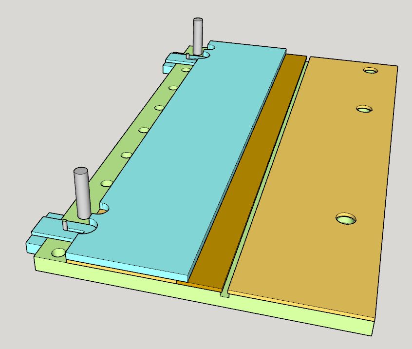
I wanted a base board with a T-groove to accommodate a couple of quick lever guide rail clamps and a couple of runners for an adjustable stop. Normal t-track wont' accept the clamps and I don't have a T-slot cutter so I decided to use a mixture of 25mm and 6mm mdf to create the base. The section coloured blue in the design above represents the adjustable stop which doubles up as the support for the guide rail.
The Build
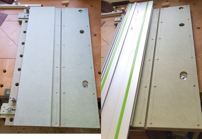
The design evolved and there are unnecessary elements in the build. I started off with an off-cut of 25mm MRMDF measuring approx 825mm x 470mm. At the moment I don't envisage needing strips longer than 600mm so that would be more than adequate. I have an 800mm guide rail that would work well on this jig.
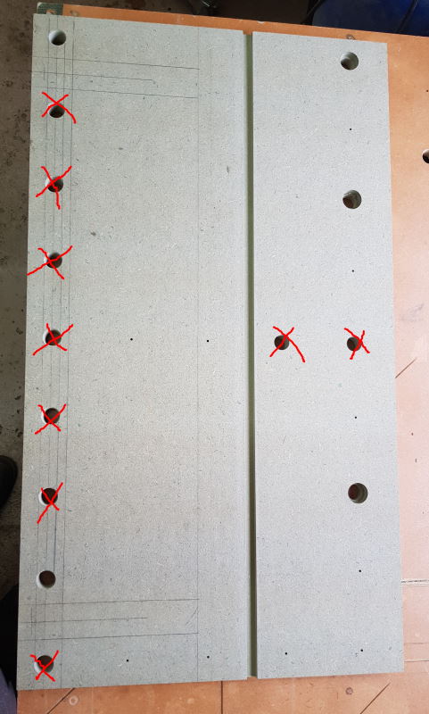
I wasn't clear where I was going with the design initially and drilled far more more holes than I needed (I get carried away every time I get the Parf Guide out). Those crossed out won't be of any use. The three holes on the right are for bolting the jig to my MFT table. The groove is 12.7mm wide and 7mm deep and positioned to be about 50mm to the right of the edge of the guide rail when in use.
The first two pieces of 6mm MRMDF added to form the T-Slot. The cut line will occur on the narrow left-hand strip - this can be replaced if it gets chewed up horribly, but that shouldn't be necessary.
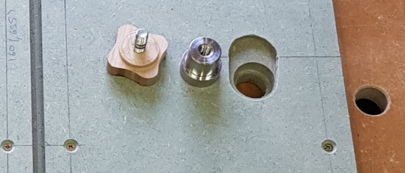
I'd forgotten to cut out access to the fixing holes under the right-hand piece of 6mm MRMDF so retrofitted these, but lost concentration to the radio play I was listening to - :roll: . Anyway, it helps show the fixing method more clearly. I use a couple of the original collared Parf Dogs with a bolt to screw through from the underside of the bench top - if that makes sense.
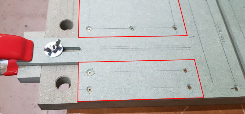
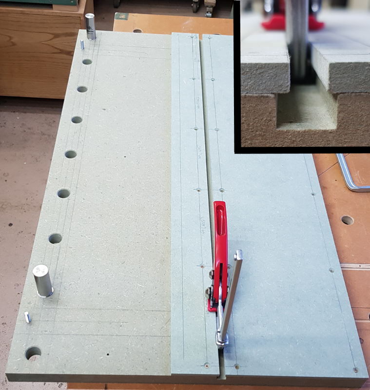
Three more pieces of 6mm MRMDF are screwed to the baseboard to create the grooves for the runners of the adjustable stop (one of which is shown above) and a couple of M6 bolts fixed into the base board on the centre line of the runners. While I had the runners positioned as far to the right as possible I added block to the overhanging end of the runners using instant glue. Once fixed the blocks were screwed to the runner as well.
For my purposes i.e. cutting 12mm wide strips I used two pieces of 6mm MRMDF glued together to make a 12mm thick stop board. I'll return to this later.
The 12mm board was cut so that it was wider than needed. I fixed it in place on the runners using double-sided tape and then removed the runner and board assembly to screw the runners to the stop board. Once it was fitted back to the jig, I made sure the runners were pushed as hard right as possible and, using a full length guide rail, cut through the stop board aiming to set the adjustable stop to zero. And that completed the build.
Testing the Jig
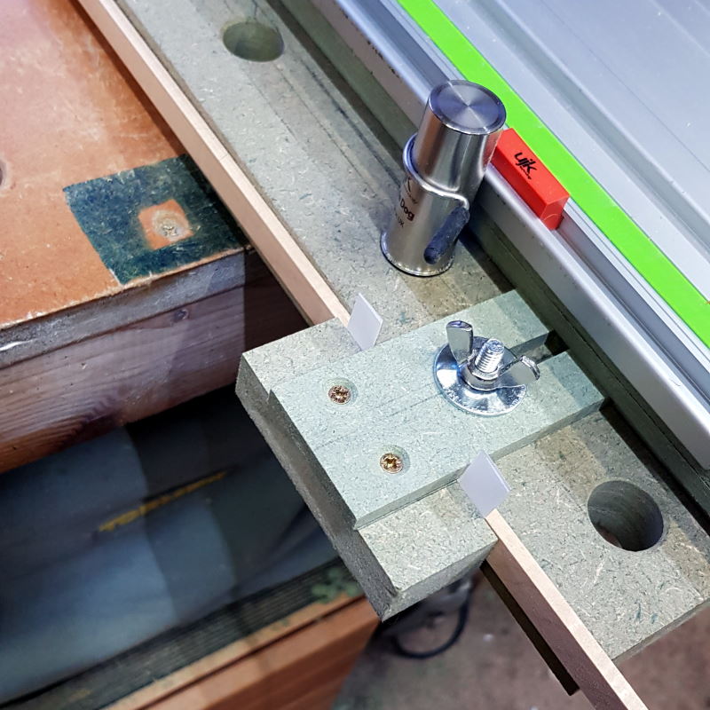
I'd hoped that I could simply wedge a strip of the desired thickness (4mm in this test) between the edge of the base board and the stop blocks on the runners but the first test cut came up 0.2mm short so I added a couple of folded paper shims to correct this.
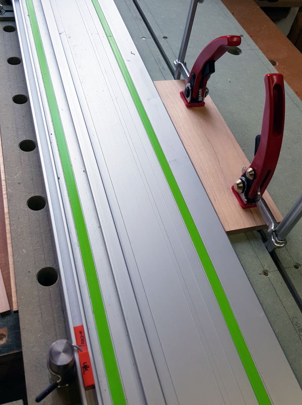
If cutting strips from a board more than 55mm wide, the quick lever clamps can be used directly on the board. I wanted to use single-hand operation clamps so I could maintain pressure on the board so that it was tight against the stop block under the guide rail.
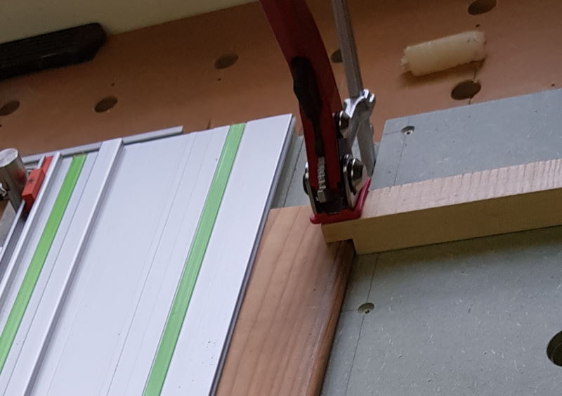
If the board is narrower than 55mm then it can be clamped using a couple of hold-down blocks.
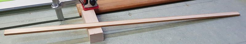
The resulting test strip. It measures 4.02mm at one end and 4.05 mm at the other end. That'll do for me!
This setup is for 12mm wide strips but you could make up adjustable stop components to suit each width required.
In practice this could cut strips up 30 mm thick as it stands. The design drawing shows cutouts for the adjustable stop to go around the Parf Dogs that hold the guide rail. I'll cut those out if and when I need them but I don't anticipate wanting to go beyond 20mm.
I feel very safe using the jig. The main board being cut will not move as it is held by the clamps. The strip is unsupported once the blade has made the cut (see below) but I am not worried about it being ejected towards me as I'm standing at the jig as a) it is most likely to be propelled forward due the direction of the blade and b) the strip won't carry much mass. But in the trials it wasn't ejected.
If I were to make this again
Firstly, I'd only drill the holes that I needed! But the extra holes do no harm so this prototype will suffice as the completed jig.
I set the T-groove 50mm away from the edge of the guide rail. However, once I added the splinter guard shoe to the track saw it just catches the clamp so I'd position the groove 60mm from the guide rail edge.
The thickness of the board for the adjustable stop could do with being just a hair under the desired width of the thin strip. For example, if I want to produce 12mm thick strips I would use a stop board 11.9 mm thick so that when the board to be cut was put under the guide rail, the guide rail splinter strip is making firm contact with the board to be cut and therefore doing its 'splinter guarding' efficiently as well as giving a slight holding pressure once the cut is made.
Cheers, Trevor
I've become hooked by the geometric world of Kumiko and have several projects in mind. My first effort is posted in this topic. My dilemma was the production of the thin stock required. For now I've settled on using 12mm wide stock. For my initial efforts I was preparing stock to 12mm thick boards on the planer thicknesser. That's always going to be the starting point so no problem with that.
For the next stage I used the bandsaw to rip a strip of the prepared board about 2mm over size i.e. for a finished thickness of 3mm I was ripping a 5mm strip. After each rip cut I then tidied up the sawn edge on the Planer before ripping the next strip etc. until I'd got through the prepared boards. That then left me with strips with one planed side and one sawn side which needed cleaning up.
I used a wide base board to send multiple strips through the Thicknesser, having checked for grain direction to determine the best direction to orientate them and used double-sided tape to hold them down on the board at the start and end of the strips. Then, using the lightest cuts possible I thicknessed them down to 3mm. The success rate was probably around 90% with a few strips tearing out or splintering under the cutting action.
This was all pretty time consuming and not entirely satisfactory given the success rate. The finish on the strips doesn't have to be super smooth and I would be happy with the finish straight from a cut on the table saw. The extra waste from the thickness of the blade kerf would be similar to the extra I allowed for the thicknessing before so it would be about as economical. I spent far too many hours searching out information on cutting thin strips, mostly using a table saw but I wasn't sure I wanted to use any of these for mass production. Running the blade 3mm from the fence was never going to happen! The safest looking solution on the tablesaw seemed to be the use of a stop fixed to the off-cut side of the blade whereby the fence was set so the board width fitted between the fence and the stop, with the fence being repositioned after each cut. I didn't like that approach as my fence doesn't move strictly parallel to the blade so adjusting the position is slow.
I toyed the idea of using a ripping sled to clamp the board onto to perform the cuts safely but that threw up as many problems as part-solutions, most problematic around the accurate positioning of the board for a consistent thickness. Then I found a video of someone using a track saw and some very expensive parallel guides to perform repeatable thin rips. So I turned my attention to the track saw as the solution - should have gone that way first as I do love my track saw. What I came up with is probably not unique but I couldn't find anything similar on the web so read on if you're looking for a similar solution.
The Design
I wanted a base board with a T-groove to accommodate a couple of quick lever guide rail clamps and a couple of runners for an adjustable stop. Normal t-track wont' accept the clamps and I don't have a T-slot cutter so I decided to use a mixture of 25mm and 6mm mdf to create the base. The section coloured blue in the design above represents the adjustable stop which doubles up as the support for the guide rail.
The Build
The design evolved and there are unnecessary elements in the build. I started off with an off-cut of 25mm MRMDF measuring approx 825mm x 470mm. At the moment I don't envisage needing strips longer than 600mm so that would be more than adequate. I have an 800mm guide rail that would work well on this jig.
I wasn't clear where I was going with the design initially and drilled far more more holes than I needed (I get carried away every time I get the Parf Guide out). Those crossed out won't be of any use. The three holes on the right are for bolting the jig to my MFT table. The groove is 12.7mm wide and 7mm deep and positioned to be about 50mm to the right of the edge of the guide rail when in use.
The first two pieces of 6mm MRMDF added to form the T-Slot. The cut line will occur on the narrow left-hand strip - this can be replaced if it gets chewed up horribly, but that shouldn't be necessary.
I'd forgotten to cut out access to the fixing holes under the right-hand piece of 6mm MRMDF so retrofitted these, but lost concentration to the radio play I was listening to - :roll: . Anyway, it helps show the fixing method more clearly. I use a couple of the original collared Parf Dogs with a bolt to screw through from the underside of the bench top - if that makes sense.
Three more pieces of 6mm MRMDF are screwed to the baseboard to create the grooves for the runners of the adjustable stop (one of which is shown above) and a couple of M6 bolts fixed into the base board on the centre line of the runners. While I had the runners positioned as far to the right as possible I added block to the overhanging end of the runners using instant glue. Once fixed the blocks were screwed to the runner as well.
For my purposes i.e. cutting 12mm wide strips I used two pieces of 6mm MRMDF glued together to make a 12mm thick stop board. I'll return to this later.
The 12mm board was cut so that it was wider than needed. I fixed it in place on the runners using double-sided tape and then removed the runner and board assembly to screw the runners to the stop board. Once it was fitted back to the jig, I made sure the runners were pushed as hard right as possible and, using a full length guide rail, cut through the stop board aiming to set the adjustable stop to zero. And that completed the build.
Testing the Jig
I'd hoped that I could simply wedge a strip of the desired thickness (4mm in this test) between the edge of the base board and the stop blocks on the runners but the first test cut came up 0.2mm short so I added a couple of folded paper shims to correct this.
If cutting strips from a board more than 55mm wide, the quick lever clamps can be used directly on the board. I wanted to use single-hand operation clamps so I could maintain pressure on the board so that it was tight against the stop block under the guide rail.
If the board is narrower than 55mm then it can be clamped using a couple of hold-down blocks.
The resulting test strip. It measures 4.02mm at one end and 4.05 mm at the other end. That'll do for me!
This setup is for 12mm wide strips but you could make up adjustable stop components to suit each width required.
In practice this could cut strips up 30 mm thick as it stands. The design drawing shows cutouts for the adjustable stop to go around the Parf Dogs that hold the guide rail. I'll cut those out if and when I need them but I don't anticipate wanting to go beyond 20mm.
I feel very safe using the jig. The main board being cut will not move as it is held by the clamps. The strip is unsupported once the blade has made the cut (see below) but I am not worried about it being ejected towards me as I'm standing at the jig as a) it is most likely to be propelled forward due the direction of the blade and b) the strip won't carry much mass. But in the trials it wasn't ejected.
If I were to make this again
Firstly, I'd only drill the holes that I needed! But the extra holes do no harm so this prototype will suffice as the completed jig.
I set the T-groove 50mm away from the edge of the guide rail. However, once I added the splinter guard shoe to the track saw it just catches the clamp so I'd position the groove 60mm from the guide rail edge.
The thickness of the board for the adjustable stop could do with being just a hair under the desired width of the thin strip. For example, if I want to produce 12mm thick strips I would use a stop board 11.9 mm thick so that when the board to be cut was put under the guide rail, the guide rail splinter strip is making firm contact with the board to be cut and therefore doing its 'splinter guarding' efficiently as well as giving a slight holding pressure once the cut is made.
Cheers, Trevor