Thein Seperator WIP - resurrected thread

UKworkshop.co.uk

Help Support UKworkshop.co.uk:

This site may earn a commission from merchant affiliate links, including eBay, Amazon, and others.
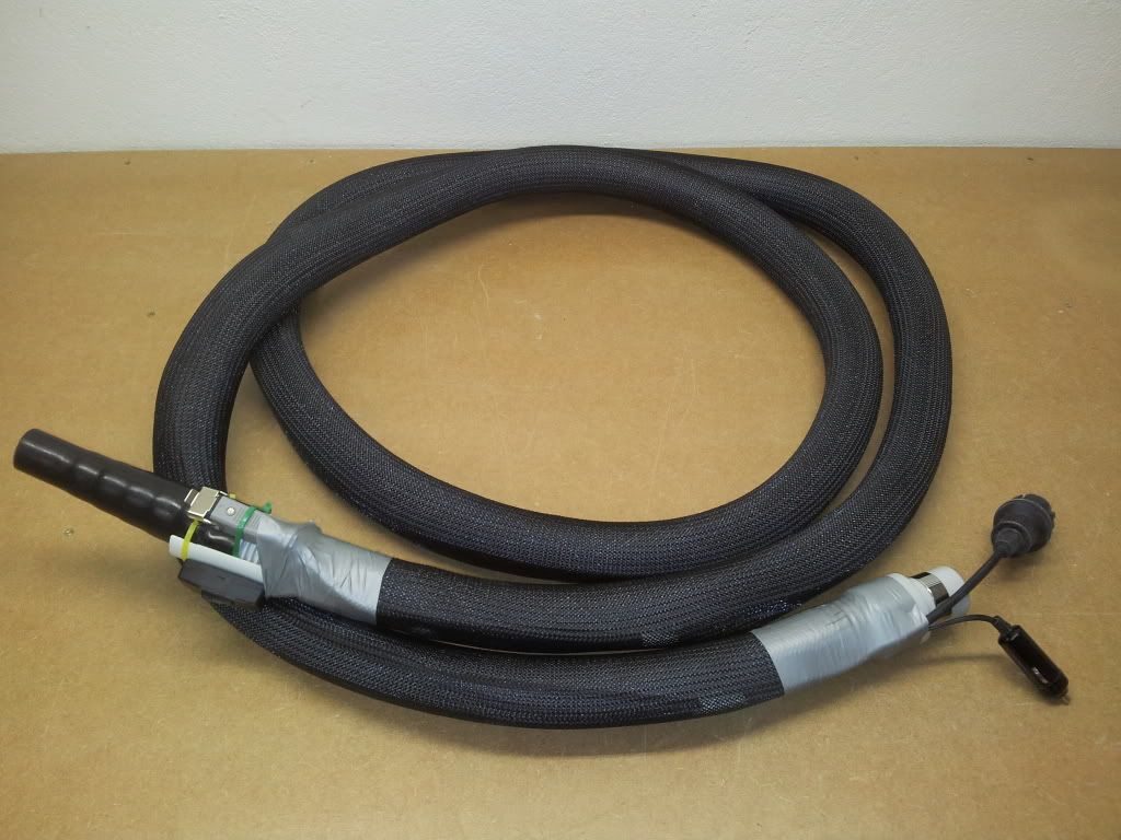
IEC type connectors are the obvious choice, easy to get hold of and cheap. However, I was worried they would too easily come apart (male/female) without some form of mechanical locking, bayonette or similar. You should also consider the dust ingress problem and I doubt normal computer type IEC connectors have a particularly high IP rating.
The ones I've used are not completely ideal and I don't like that clip affair flapping about all the time, but they are rated IP54 and at the time were the best I could find.
You may want to check out RS Components http://uk.rs-online.com/web/ and look for XLR connectors with bayonette locking.

Mark
 
I mentioned braided sleeve earlier. Here's the complete 4m extraction hose with said sleeve installed. Instead of heat shrink shroud I sealed the ends with thin duct tape.
230VAC mains plug and 12VDC starter plug at right.
230VAC mini mains plug and 12VDC starter switch at left.

Mark

braidedsleevehose.jpg
 
And so to the chip extractor (HVLP) system.
I'd already installed most of the fixed pipework in the walls as shown in earlier posts/pictures.
First thing to fix was blastgates. I took Bob (9fingers) advice and made them straight through type.

Sides from 19mm MDF, gate plate from 6mm.
One side is an Axi hose joiner cut in half (2 gates from one adaptor :wink: ).
The other side is a short length of soil pipe.
Both attached with 3x20mm countersunk screws and then sealed round with silicon.
P1010309.jpg


The gate is simply pushed onto the end of the fixed pipe protruding from the wall (rubber gasket) and then screwed to the wall with a long screw and spacer (bits of electrical conduit) in each corner.
Open position.
P1010311.jpg


This one's for the floor-sweep/Gulper. The other two adjacent are for under the table saw and under the router table.
The wing bolt (in a captive nut) locks the gate so gravity doesn't take over :wink:
Closed position.
P1010312.jpg


I admit they're not very pretty but hopefully they'll do the job - for almost zero outlay.
I've not hooked up the chip extractor yet so have no idea whether they work, but I'm hopeful :D

Mark
 
Have finally completed the chip extractor system.

The Axminster ADE2200.
I hung the fan from the roof to keep the intake as short as possible. Out from the fan, round the corner to the workshop and past the PT is all 6" pipework.

hvlp1-1.jpg


Two droppers and blastgates to the PT.

hvlp2-1.jpg


After the PT the pipework reduces to 5" for about 1,5m and then down to 4" soilpipe which I've hidden behind the wall panelling.
Next machine is the pillardrill.

hvlp3-1.jpg


Then round the corner and along the back wall to two outlets at roof height for the router table fence (am building a new router table now) and TS-crownguard, and then 3 droppers to outlets at floor level for under the router table, under the table saw and for the Gulper/floor sweep. You can just see the floor sweep, with extendable Rockler hose, in the first picture.
Lastly the pipe continues at roof level to the bandsaw.

hvlp4.jpg


That's it :D

Oh, and it works :wink:

Mark

hvlp5.jpg
 
3 years on and I'm back :D

Time to resurrect this thread I think :D .
The Axi extractor has worked just fine but cleaning out that filter is a pain in the butt :x
I don't have the space for a full blown cyclone so decided to go for next best and make a Thein Seperator.
The design is basically Pitbull's http://www.jpthien.com/smf/index.php?topic=429.msg2187#msg2187 but with a number of my own changes.

Here's what I've done so far :-

The bin is purely coincidentally the same 120 litre drum Pitbull used.
thein6.jpg


The bottom (and top - not shown in pictures) are 15mm ply (Pitbull used MDF)
The side I made from 16mm MDF in the same way as Pitbull but the other way round, with the relief cuts on the outside. I tried his ply bending method but mine snapped every time :( I'll probably cover the outside with thin plastic sheet to cover up the splits.
To save on materials I cut the strip from the width of an 8 x 4 sheet and then joined on short peices at either end to extend to the required 1,6m. Joined with biscuits and glue and clamped along the bench with dogs and one of those Veritas pup things.
thein5.jpg


More to follow.
Chears
Mark
 

Attachments

  • thein6.jpg
    thein6.jpg
    43.1 KB · Views: 162
  • thein5.jpg
    thein5.jpg
    51.8 KB · Views: 162
I made a big thein baffle that sits on top of a 55gallon barrel. To make the curved wall of the baffle I cut a section from another barrel and then cut a slot in the top and bottom to hold it in place
 
I decided to try to make the intake transition as smooth as possible by using thin steel plate. Needed a lot of fiddling with a nibbler but I got there in the end. The plan is to fill the void around the intake pipe with insulation foam and then seal everywhere with silicon.
thein4.jpg
thein5.jpg


The top of the seperator has a 16mm wide x 6mm deep groove in the understand so it sits tight over the bent MDF side. The whole lot will then be held together by threaded studing into captive nuts on the underside of the bottom flange.

One thing I forgot to mention is that all the pipes are 6 inch (not the normal 4") and the seperator is sized accordingly.

Nearly there now :D

Mark

thein6.jpg
 

Attachments

  • thein4.jpg
    thein4.jpg
    124.3 KB · Views: 143
  • thein5.jpg
    thein5.jpg
    99.3 KB · Views: 143
  • thein6.jpg
    thein6.jpg
    89.1 KB · Views: 143
If you need to try kerf bending ply again try and cut right into the last lamination and use some hot water on the ply, worked for me on quite a tight radius with 12mm plywood.
 
Blended in the intake with glass fibre body filler

20150707_225326_resized.jpg


The easiest way to fill the relief cuts was with loads of thin MDF strips. When the glue is dry I'll sand back and finish with a smear of filler.

20150707_225344_resized-001.jpg
 

Attachments

  • 20150707_225326_resized.jpg
    20150707_225326_resized.jpg
    229.7 KB · Views: 107
  • 20150707_225344_resized-001.jpg
    20150707_225344_resized-001.jpg
    93.6 KB · Views: 107
All sanded and ready for the top to og on.

20150708_185028_resized.jpg


I put the whole thing on a simple base With casters.
Ready for Paint.

20150708_184718_resized-001.jpg
 

Attachments

  • 20150708_185028_resized.jpg
    20150708_185028_resized.jpg
    232.5 KB · Views: 106
  • 20150708_184718_resized-001.jpg
    20150708_184718_resized-001.jpg
    142.6 KB · Views: 106
View inside showing downpipe.

20150708_184752_resized.jpg


Small ply blocks on the ends of the threaded studs.

Mark

20150708_185055_resized.jpg
 

Attachments

  • 20150708_184752_resized.jpg
    20150708_184752_resized.jpg
    191.3 KB · Views: 93
  • 20150708_185055_resized.jpg
    20150708_185055_resized.jpg
    212.1 KB · Views: 93
A couple of pipe connections to sort out but otherwise finished.
The exhaust connection is temporary until I can get hold of a length of 5 inch flexible. The plan is to run the exhaust straight out through the wall (as now connected) during the summer and via the filter during the winter.

20150721_225132_resized_1.jpg


Reduced waste bag under the filter

20150721_225257_resized_1.jpg
 

Attachments

  • 20150721_225132_resized_1.jpg
    20150721_225132_resized_1.jpg
    231.3 KB · Views: 70
  • 20150721_225257_resized_1.jpg
    20150721_225257_resized_1.jpg
    218.4 KB · Views: 70
I was expecting the introduction of a seperator would adversly effect the performance of the system but had nor reckoned on how much :shock:
After studying things for a few days I concluded that the main problem was the complicated duct arrangement above the PT and the sloping duct down to the seperator. Also, the pipe between the extractor and the top of the seperator was probably both too long and not straight enough.
The following pictures show the modifications I've now made, before and after.
The improvement has been dramatic and the suction is now better that it was before I added the sperator. A real result :D

duct1 (640x360).jpg


duct2.jpg


duct3.jpg


duct4.jpg


The branch that used to go to the planer I've now extended straight down to the floor and built a floor-sweep at the bottom in addition to a take-off for the "hoover" hose.

duct5.jpg


Mark
 

Attachments

  • duct1 (640x360).jpg
    duct1 (640x360).jpg
    188.7 KB · Views: 47
  • duct2.jpg
    duct2.jpg
    248 KB · Views: 47
  • duct3.jpg
    duct3.jpg
    136.3 KB · Views: 47
  • duct4.jpg
    duct4.jpg
    137.5 KB · Views: 47
  • duct5.jpg
    duct5.jpg
    139.4 KB · Views: 47
Krysstel":19sqlnws said:
I was expecting the introduction of a seperator would adversly effect the performance of the system but had nor reckoned on how much :shock:
After studying things for a few days I concluded that the main problem was the complicated duct arrangement above the PT and the sloping duct down to the seperator. Also, the pipe between the extractor and the top of the seperator was probably both too long and not straight enough.


The improvement has been dramatic and the suction is now better that it was before I added the sperator. A real result :D
Mark

Another reason for less good performance is your very long lengths of flexible hose. The flexible section should be as short as possible because it is a very big reducer of airflow due to the corrugated nature of the walls.
 
sometimewoodworker":1xb0m6un said:
Another reason for less good performance is your very long lengths of flexible hose. The flexible section should be as short as possible because it is a very big reducer of airflow due to the corrugated nature of the walls.

I agree and I'm planning to reduce some of them as much as possible - particularly the one to the table saw crown guard.
The long hose in the last picture is an expandable floor-sweep hose not a hose that I use to connect to any machine.

Mark
 
Back
Top