The secret to cambering Bevel Up plane blades

UKworkshop.co.uk

Help Support UKworkshop.co.uk:

This site may earn a commission from merchant affiliate links, including eBay, Amazon, and others.
From Derek's description and photos, he rolls the template back and forth on the rest. If the edge follows the template, he must do this for about the same number of revolutions at each point.

Hi Ivan

That is exactly what I do.

I wish I could take a video to reveal the technique. Yes, there is handskill involved (I'd like to believe that! :D ) but the template is also doing its work to create a specific camber.

Perhaps someone on the forum would try replicatng the template and the action as I described it?

Regards from Perth

Derek

There is no doubt your process can generate a cambered blade. I (for one) have no need of third party proof of this.

My continued doubt is that the camber on the template is in any way "generative" of the camber on the blade.

I know that a shallow camber can be made with any pivot small enough to allow the needed swing, because I've done it.

http://www.geocities.com/plybench/scrub.html#blade

In this case, the pivot is the single narrow roller (wheel!).

I believe I've demonstrated (verbally) that your template could (rather easily) make a straight across blade.

So I am at a loss to see why the blade camber should match the template camber, other than operator input (which clearly works)

I would welcome explanations though.

BugBear
 
I believe Bugbear and Ivan are both correct. Bugbear is correct in that it is operator input that is making the jig work properly. But Ivan has explained that rolling the template along the control bar results in a radius on the blade edge which would require a considerably longer (more distant) point radius. Indeed, one could start with the sagitta = 1/16" and the blade width, and calculate what the equivalent point radius would be, measured along the slant of the primary bevel.

Derek's contribution, as Ivan explains, is that his jig (applied with requisite skill as BB explains!), can produce smaller sagittas without having to use point-pivot jigs with impractically long radii.

Wiley
 
The camber produced is slightly larger than that on the jiggy as long as there are no user corrections made, no matter how subtle. That's the physics of it. At least if this were a single-pivot point jig. Here's how I think a single-pivot jiggy would work...

The closer the edge is to the jiggy, the less this offset or difference is. I suspect that without user input the difference on a 2" blade, a 2.5" desired radius, and having a 1.5" projection is about 1.5" difference (a blade ends up with a 4" radius). I believe that same difference in radius holds true using the same projection no matter the start/end radii. At least that's how it seems to my mind.

But, Derek's jig isn't pivoting on a single point. I think if the point on the jiggy and the edge of the blade are kept relatively square to each other at the point of the blade's contact to the sander/grinder wheel, the blade will end up with the same radii as the jigs used. If I was better at using CAD, I would try to draw it. If I had more time, I would make one to try on a piece of scrap saw steel. If nothing else, it is removing some of the radius "growth" inherent in a single-pivot point jiggy.

The skill comes in by not lingering in one spot longer than another--which is helped by drawing the arc onto the non-beveled side of the blade to be cambered. The jiggy keeps the projection relatively even through the arc (unlike a single-pivot). It still takes operator error to not remove say more in the center than the corners and vice versa.

In one sense, it doesn't matter. The main benefit is that it is reproducable.

Take care, Mike
who only cares that his pattern maker's blades and rounds are accurate--they need to match the soles...
 
A very interesting discussion, in which I have learnt a number of things about cambered blades.

The similarity between the template and the blade shape leads one to the conclusion that one can only lead to the other. BugBear has noticed and explained well the weakness of the linkage. People trying this at home could easily get a very different curve. Which means of course, a variable bevel angle across the blade. An arc scribed on the back would certainly help.

Assuming a rod based tool rest (rather than a flat tool rest at the desired angle), then I think Derek's jig is better than a point jig. If you use Derek's jig and grind to an arc scribed on the back, then the resulting bevel would have a constant included angle. If you use a point in the middle and grind to an arc on the back, you get a variable included angle (smaller away from the middle).

The standard method, assuming you have a belt sander or grinder and an appropriate tool rest,

1 scribe the desired curve on the back,
2 grind at 90 degrees to achieve that edge shape,
3 grind the bevel at the desired angle just up to the edge,

produces a surer arc faster. Even with a tool rest (which helps with the bevel angle), it would be possible to get a different edge shape without the arc. Grinding to an inscribed arc, then grinding the bevel to that arc, together help to get the desired shape. Trying to do both in one step might lead to a blued edge.

Finally, a question.

An earlier post showed an alternative jig design that was claimed to be better than Derek's design. I cannot see why it is an improvement. Can someone help me on this?
 
Brent,

I did not study the diagram properly, but think it is like the set up in my second book, used to produce blades for a hollowing plane, with curved sole..

The angle is controlled by a fixed sloping plane.

The radius is set from an adjustable but but finally fixed pivot point.

This produces exact repeatable curve without any skill input, or feel from the operator. It could be done with a blindfold on.....

best wishes,
David Charlesworth.
 
MikeW":15stozr9 said:
The camber produced is slightly larger than that on the jiggy as long as there are no user corrections made, no matter how subtle. That's the physics of it. At least if this were a single-pivot point jig.

I think an important point is being missed.

All the statements about circles and radii would only be true if the grinding surface were vertical (i.e. 90 degree bevel!!). Under this circumstance, the grinding process would cease for any given distance, allowing the (square) end of the blade to be ground to a camber, in the manner suggested by several people.

camber_template.png


On the right we have a grinding belt, the blade is blue, the bar is ref, the template is brown(ish) and the grinding rest is back.

In the upper diagram, grinding cannot proceed beyond the limit set by the template, and thus the template can generate a camber (and the various discussions about shapes and radii are applicable).

In the lower diagram, which reflects the actual situation (with a realistic bevel) grinding can go "too far" by simply making the bevel steeper and steeper, and thus the template cannot "generate" the camber.

BugBear (who continues to point out that Derek's blades come out just fine)
 
bugbear":3qgw40sn said:
All the statements about circles and radii would only be true if the grinding surface were vertical (i.e. 90 degree bevel!!). Under this circumstance, the grinding process would cease for any given distance, allowing the (square) end of the blade to be ground to a camber, in the manner suggested by several people.

With turning tools I have ground the edge vertically to get the shape I want, then ground the bevel using a platform to bring the bevel to the shape; it is very easy to see where you need more/less grinding. All in all, not a bad method. Should work here too.
 
I too fear the point is lost, BB.

What do we make of the scientist who doesn't try the solution to a problem choosing to rather rationalize why it won't work? Proving or disproving through trial and error is still the scientific method, eh?

In that vien, I went out and tried Derek's jiggy and a single-point version. Both work. The single-point requires more user intervention and changes the bevel angle as it moves to the outer edges. Which makes sense as that is how one produces a fingernail grind on a turning gouge. Derek's jiggy produces an even bevel angle.

The single-point changes the distance from the pivot-point to the edge. The other jiggy does not.

However, there is nothing in Derek's jiggy (or the other) to prevent one from over grinding and thus changing the desired camber. That part is user experience.

The solution to that "problem," it seems to me, is to first do what I have always done which is to grind the profile at 90 degrees and grind the bevel to nearly the edge and hone from that point on.

I look at the issue this way. A honing jig is just that--it is a holder to aid in fixing the bevel angle and desired shape. This is the same with the cambered roller on the LV MK.II honing jig, the Eclipse and its clones, the MF honing jig, the Stanley et al. All of them can produce/hone the desired camber (or straight) edge--and all of them require the user to be smarter than the jiggy. Some of them produce a more consistent result easier (less user thinking and acting). But they all require user intervention.

Derek's jiggy works the same way. It isn't automatic and foolproof. But hey, why not design, build and produce one? Or instead, you could simply tell people why one or another won't/can't work.

Take care, Mike
who recognizes you recognize Derek's works for him.
 
Well, as one who has read a lot of results that worked in practise - that is, some one claimed to be able to do something - but were not reproducible, I have to take BugBear's side in this. In fact, in Mike's own (and several other people's, including mine) recommended solution, he explains exactly what is missing from Derek's approach.

When using the rod type tool rest, with no fixed angle guide, there is nothing to ensure correct angle. Chris adds that his jig had an angle plate. With an angle plate it will work for anyone, without an angle plate others trying this could easily foul up.

The alternative is a scribed arc on the back of the blade which gives the user a goal - grind to the scribe then stop (leaving the scribe just to be sure).

However, grinding the full bevel and attempting to reach the scribe both in the same operation can lead to overheating the edge - again, a problem with Derek's approach. Again, something Mike recommends against. First shape the iron, second grind the bevel.

In the grind the bevel part, if you don't have an angled plate, then a guide like Derek uses makes sense.

So, it works. It could work better with a couple of changes. Even with the changes it would not be my first choice.

Sharpening radiused blades
 
However, grinding the full bevel and attempting to reach the scribe both in the same operation can lead to overheating the edge - again, a problem with Derek's approach. Again, something Mike recommends against. First shape the iron, second grind the bevel.

Just for reference, let me remind you that I used a 40 grit belt. With a lightish touch, the belt will remove metal quite fast and without heating up too much. The beveled and cambered jack blade began life with a straight 50 degree primary bevel. A LOT of steel was removed in creating the final shape. I quenched as I worked to be safe. It did not overheat.

The belt sander is a great tool to remove a lot of metal. Nevertheless, I have done the same task (actually it was to create a scrub plane profile) with the same jig on a bench grinder - just running the curved template against the edge of the grinder rest.

Regards from Perth

Derek
 
I think there are to separate arguments going back and forth.

One is establishing the camber. BB argues (it seems) that Derek's jiggy cannot do this as is and create the same camber on the iron as that of the jiggy. It does.

The second is producing the bevel proper. Derek is doing both at once.

I think that doing both at once is prone to the problem that Brent is pointing out, that is overheating the iron. That is an issue, but it is a procedural or best practices issue.

Creating camber on an iron that matches the jiggy is separate...or at least I separate them..issue.

As mentioned, there are procedural means to obviate overheating (do the operations separate) and or consistency in the bevel angle. The latter is easily done via experience, an angled rest in conjunction with the jiggy, a combination or [insert method here]. The former also has solutions. Water-based wheels (too slow), a light touch and coarse grits (mine and Derek's prefered means), or as mentioned, doing the grinding of the camber and shaping the bevel separately. However, doing them separately also introduces the possibility of overheating too.

This is where a modicum of understanding how fast heat is generated on the various mediums and especially what one person is using or has to use. It is also good practice to never grind to the very edge on bench grinders or belt sanders--unless with experience one knows how to keep the heat from tempering on their equipment (as much art as anything) and is using dressed coarse belts/wheels. Hand-cranked and water-based systems are also viable means but slow (and one can still overheat an iron with a hand-cranked system).

So what's the point to all my rambling? None, really. The important thing is to simply get the iron(s) into the shape desired, sharp, and make something.

Take care, Mike
 
MikeW":17f84mnx said:
I too fear the point is lost, BB.

The single-point requires more user intervention and changes the bevel angle as it moves to the outer edges. Which makes sense as that is how one produces a fingernail grind on a turning gouge. Derek's jiggy produces an even bevel angle.

The single-point changes the distance from the pivot-point to the edge. The other jiggy does not.

However, there is nothing in Derek's jiggy (or the other) to prevent one from over grinding and thus changing the desired camber. That part is user experience.

Yes - points I understood but didn't state; I should have. for clarity and explicitness.

Interestingly, if one could somehow keep the assembly in the second diagram horizontal, possibly with a back rest, the jig does indeed become fully generative. Derek's jig "fails" only if the bevel angle is allowed to grind away without limit.

Your point about even bevels is well put.

There may be a discussion to be had about what template radius generates what blade radius, since the two curves are coaxial, not parallel., but I suspect this discussion would be too academic to be of interest to most.

BugBear
 
Derek's jig "fails" only if the bevel angle is allowed to grind away without limit.

BB

The simple solution/precaution is to first mark the camber outline on the back of the bevel-to-be (using the edge of the jig), then set the jig, and grind to this mark only. Do not go over it (or otherwise you need to reset the jig again).

Regards from Perth

Derek

Absolutely understood; that procedure will definitely result in the blade we (all?!) want.

BugBear
 
Provided you roll the template steadily from side to side, ensuring that all parts of the template's curve touch the tool rest, and don't linger too long in any one place, the camber will match that of the template about as well as a jig ground straight blade will match a square.

Don't forget a straight jig is grinding a camber of infinite radius....
 
Ivan was a little ambiguous when he said
the camber will match that of the template about as well as a jig ground straight blade will match a square
.

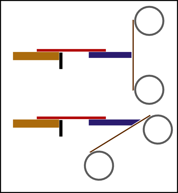
When the abrasive is wider than the blade, the edge can be very straight. With Derek's wide abrasive belt, he can put straight edges on very wide blades.

However, when the abrasive is narrower than the edge, there are problems. Notice that working a rounded edge with a flat abrasive always falls into this category. I used to grind with a 1" belt. I noticed that I could not get a really good ground edge no matter how careful I was to work steadily and carefully. That is one of the reasons I switched to a wide bench stone.

Forgetting the jig and getting back to the original post, we can split the problem into two parts -- preparing the iron, using the iron.

What can we say about preparing the iron? Until the iron goes into the plane, there is really nothing in its preparation that is affected by whether it is used bevel down or bevel up. If we can camber a bevel down iron, we can camber a bevel up iron.

It has been observed, correctly I think we can agree, that blades bedded at 12 degrees require about 3.4 times the curvature of blades bedded at 45 degrees. So, it comes to a question of degree. Can we sharpen to a smaller curvature. This is really only a problem for the extreme curvature of an iron used for scrubbing. In my experience, with radii from 6" to 3" there is not a lot more difficulty. Find a stance that lets you work through the full range of motion, practise a couple of times with the blade just off the abrasive, use light passes, ... Grinding is not much of an issue. Honing might be, but if you can hone a bevel down scrub iron you should be able to do a more extreme curve.

That leaves us with the problems during use. With 3.4 times the curvature for an equivalent use: Is there more effort? Is there faster edge wear? Is there a surface quality effect?

On surface quality, I suspect that most of the experience with surface quality and cambered blades comes from using hollows and moulding planes. There the geometry of the corners of the blade make it a scraper rather than a plane, resulting is degraded surfaces. These are final use planes - unless you sand after them. The scrub is not a final use plane, so surface quality cannot be an issue. On the much smaller radii of the jack and try planes, I would not expect it to be a problem (it is not on the corresponding moulding planes).

So, we are left with effort and edge durability as issues.

Anyone ready to try to compare the two? I might try to set up a bit of a test in the next couple of weeks. Can't be the same blade in the same plane, but something might be possible.

Brent

[Who really did not want to drag this thread out but noticed the "about as well" in Ivan's post, which is ambiguous, probably intentionally, so had to give the can one more kick and then got a little long winded.]

[Who hopes the connection stays up during submit of this second attempt. This first attempt had some comments about preparation which I hoped would not restart the discussion, but I cannot remember them now. I don't think further discussion of the grinding jig is necessary - it works.]
 
Back
Top