Small oak loudspeakers

UKworkshop.co.uk

Help Support UKworkshop.co.uk:

This site may earn a commission from merchant affiliate links, including eBay, Amazon, and others.

sploo

Somewhat extinguished member
Joined
8 Nov 2014
Messages
3,981
Reaction score
1,327
Location
West Yorkshire
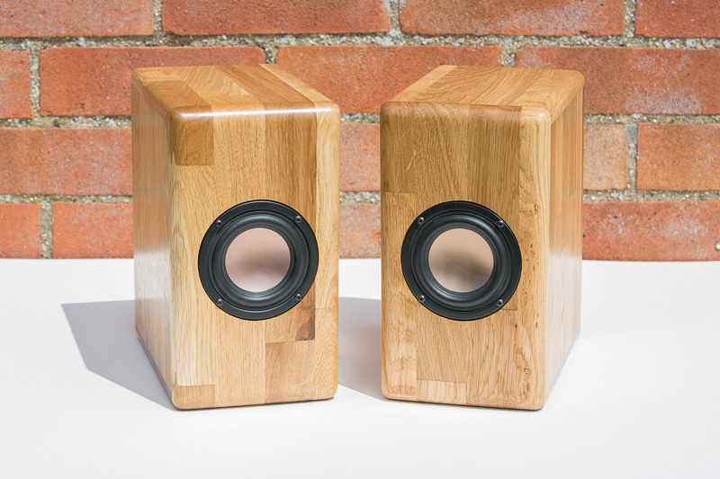
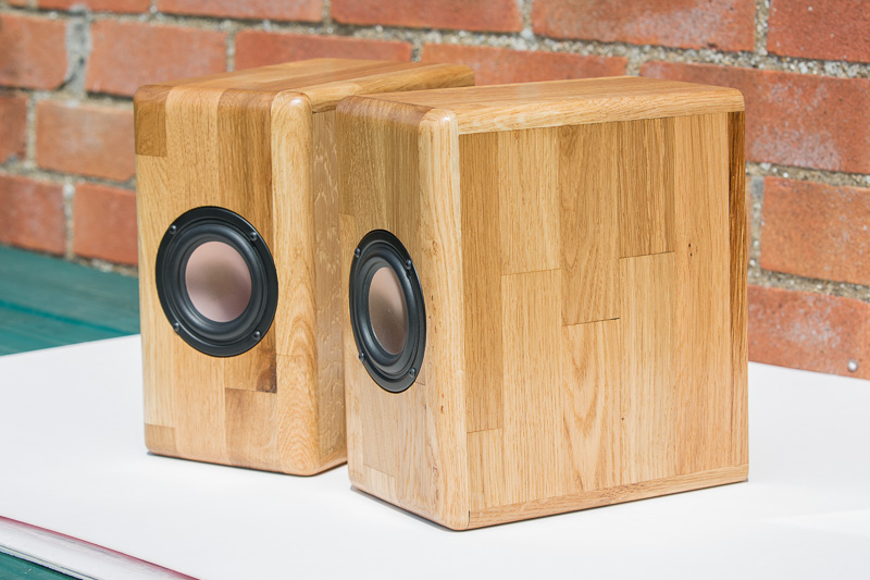
Some years ago I installed a kitchen in our house, using solid oak worktops. On top of the cabinets I have a pair of small speakers made to a Zaph Audio design (http://www.zaphaudio.com/audio-speaker18.html).

The speakers are just rough boxes in MDF, and I'd always planned to use some of the remaining worktop material to make matching speakers. Better late than never I guess.

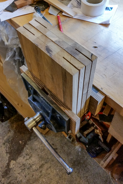
I ripped up a few sections to the rough sizes I needed, and used a marking gauge to help guide where I'd need to split the ~38mm thick material:

20160409_130242.jpg


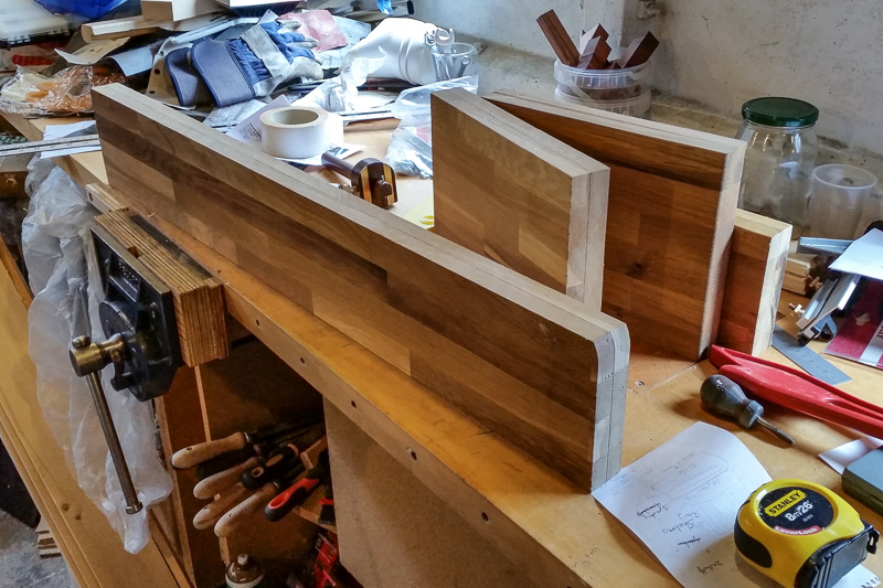
Because of the size and hardness of the material, I decided to try to reduce the load on my bandsaw by taking a series of shallow cuts over the table saw first. It's not a particularly smart thing to do, but I took a number of precautions: using a short but tall fence, a tall featherboard (before the blade), push sticks, and standing to the side of machine.

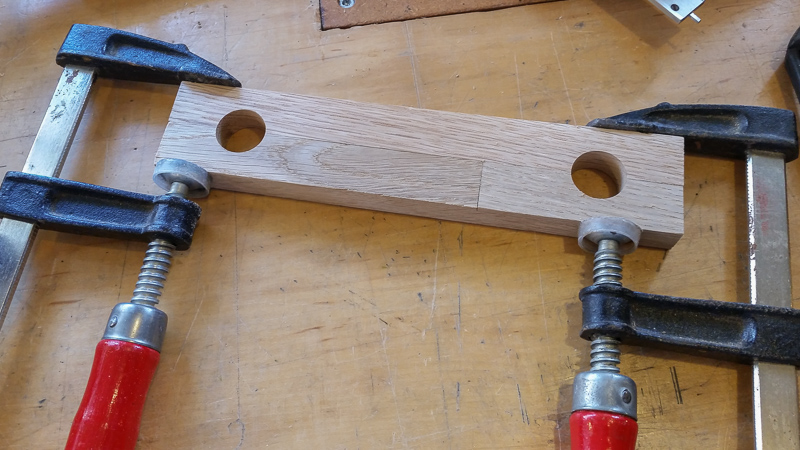
On this part you can see the small ridge left that was then cut with the bandsaw (the dark section is actually the colour of that bit of wood - it's not a burn):

20160409_134548.jpg


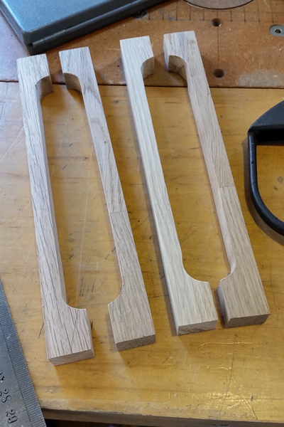
Some of the parts were too wide for my bandsaw, so once finished on the tablesaw I had to cut them by hand:

20160409_152009.jpg


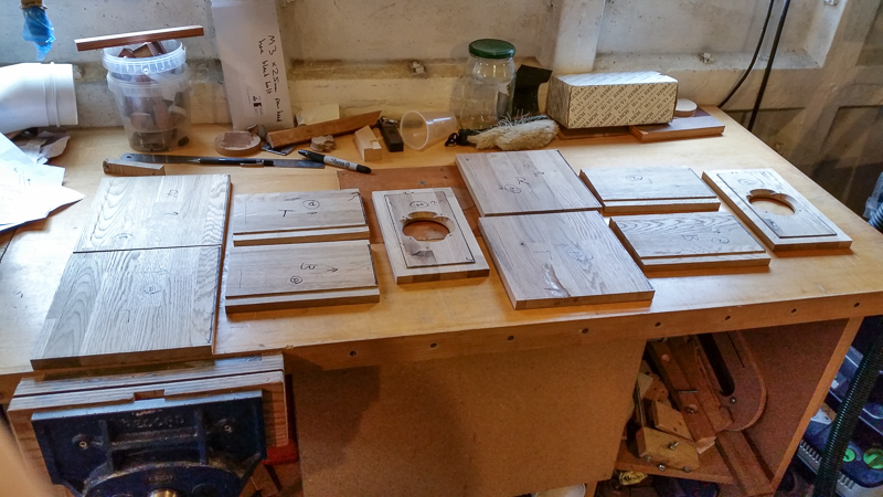
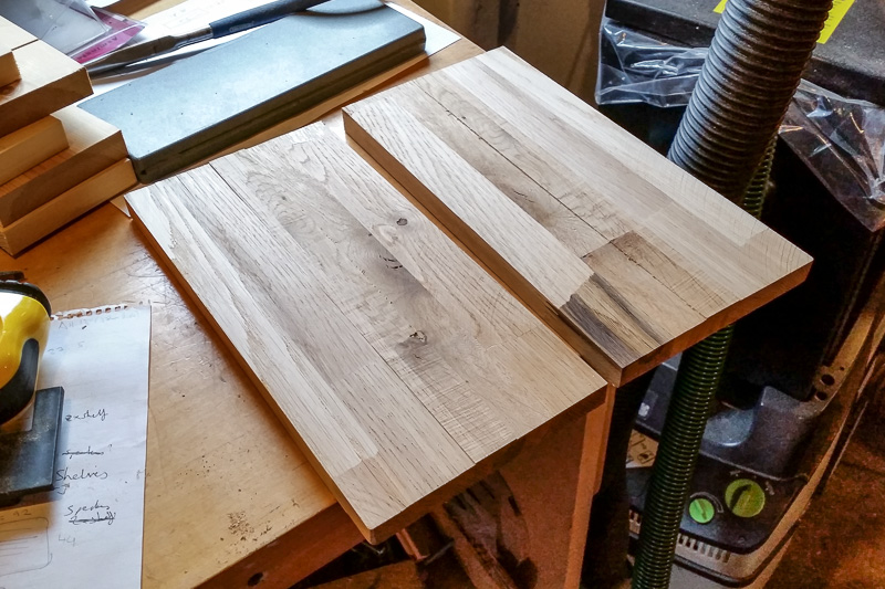
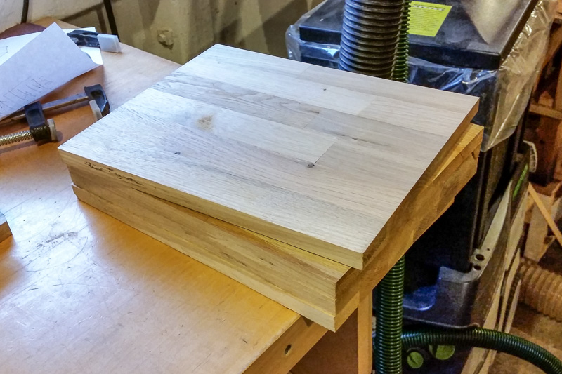
Because there was a fair bit of stock, and I really need them to be very consistent in thickness, I put them through my thicknesser (as opposed to hand planing). Here are what will be the side panels:

20160409_162359.jpg


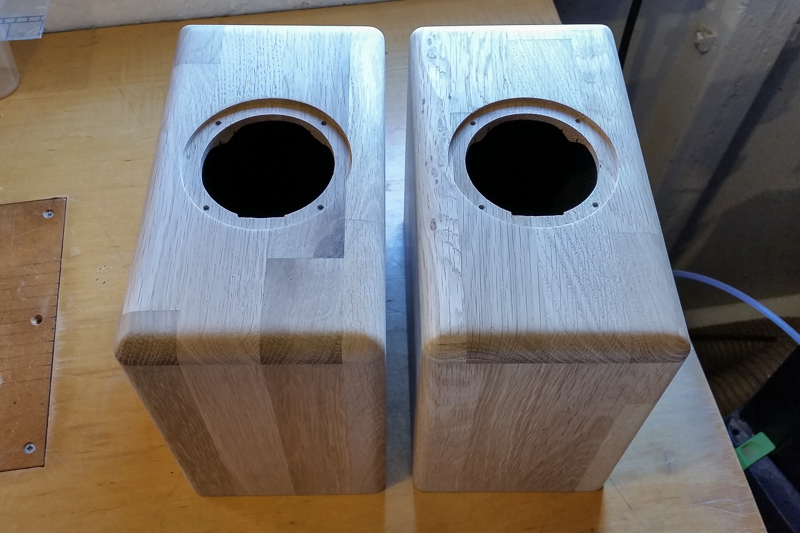
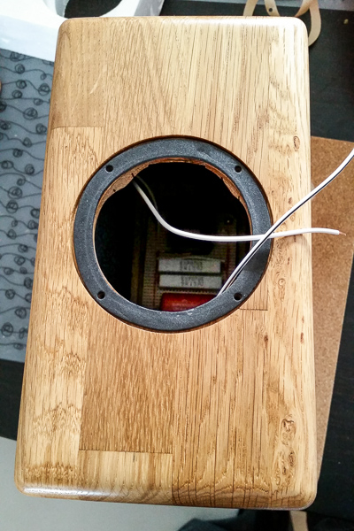
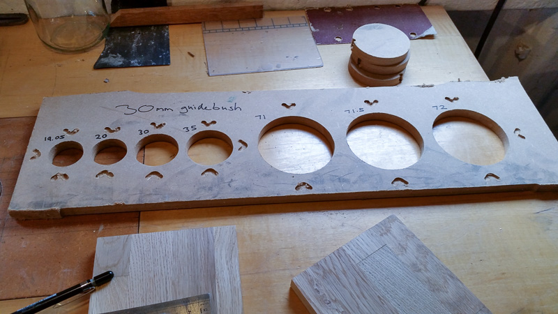
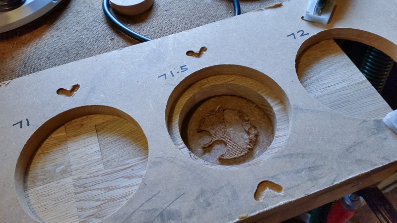
The drivers I'm using require a 71mm hole and a 90mm rebate for the flange. I couldn't find my circle cutting jig for my old router (the one not in the router table), so I decided to fire up the CNC for the first time in ages, and cut a circle jig (for a 30mm guide bush):

20160415_122827.jpg


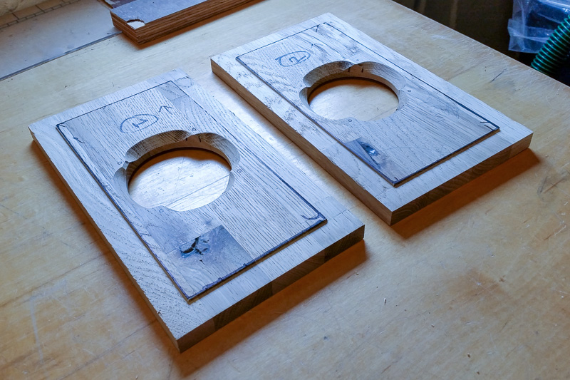
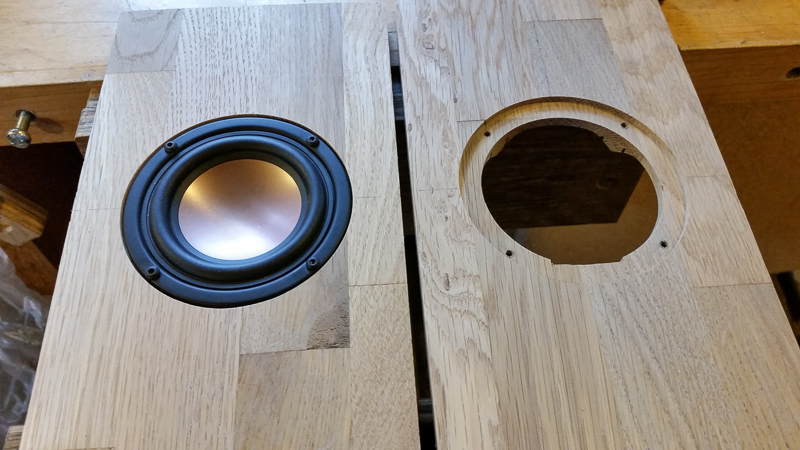
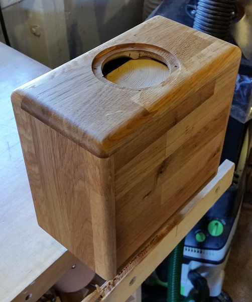
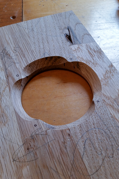
After a couple of tests on some scrap, I found the 71.5mm hole resulted in the best fit (with a rebate bit cutting a 9.5mm wide rebate afterwards). Template lined up (with some scrap underneath to protect my bench):

20160415_131559.jpg


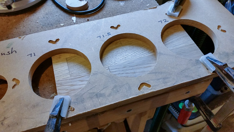
And the hole cut out:

20160415_132312.jpg


Front/top/bottom panels (you can see the rebate bit in the router table to the left):

20160415_133805.jpg


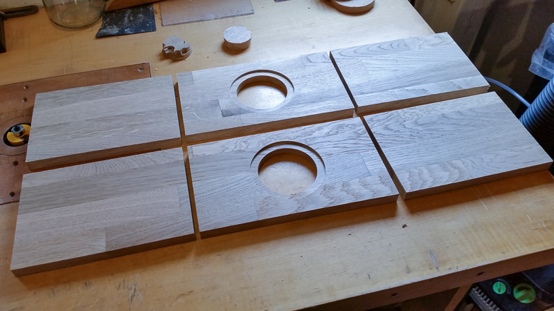
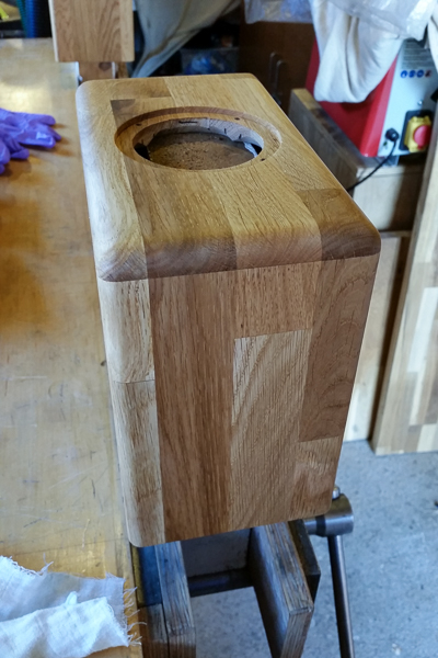
These small drivers really require a chamfer on the rear of the baffle to allow them to "breath", so I then did that on the router table too:

20160415_161156.jpg


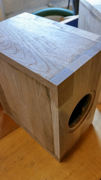
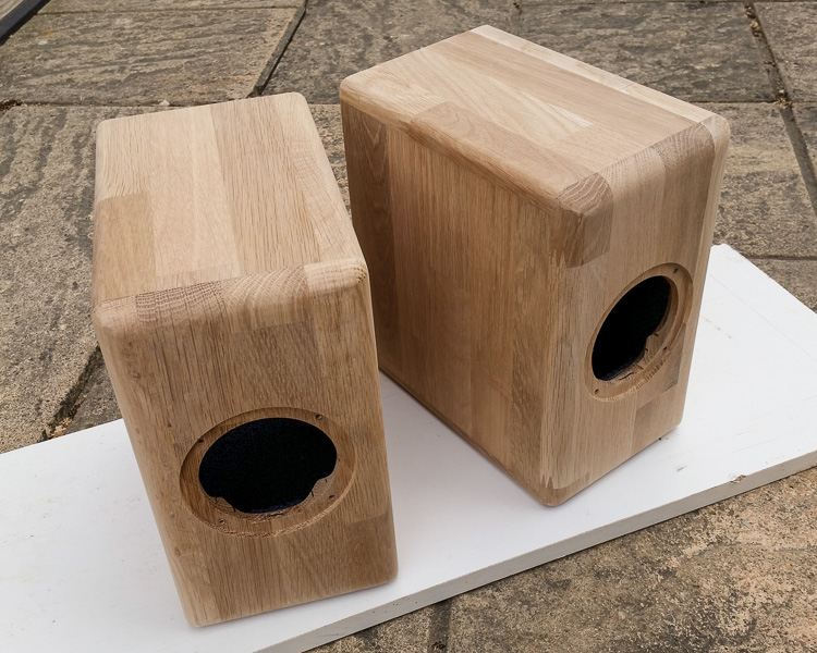
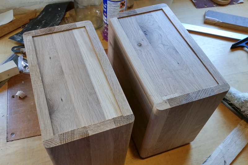
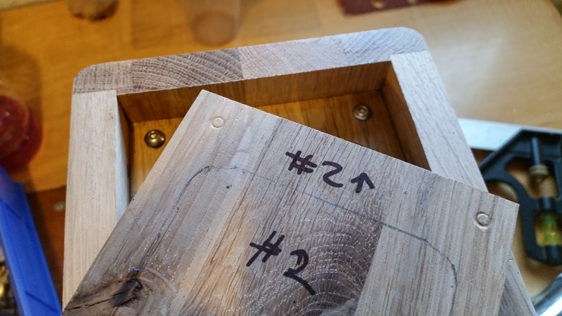
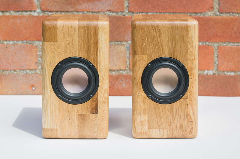
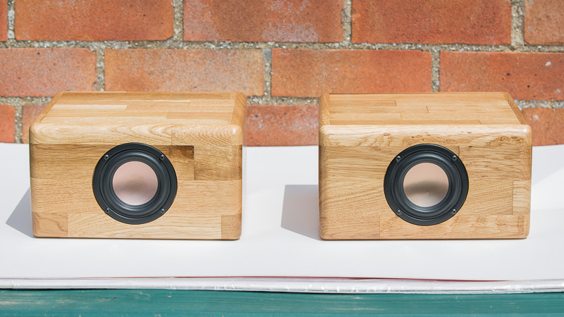
I then ran a 3mm deep rebate along the lengths of the top and bottom panels (not photographed) and loosely put the sides/top/bottom and front baffle together (with the speaker on its side):

20160415_165002.jpg


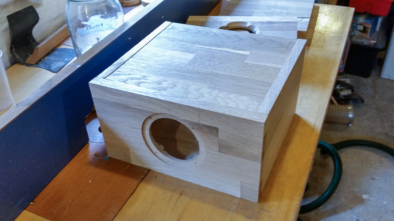
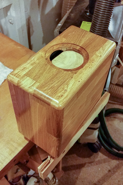
The stock is 15mm thick, and the 3mm rebate on the top/bottom panels (left/right in the photo above) is 16mm wide. This is so the edges overhang by ~1mm and can be trimmed off after glueing, for a perfect joint. The front baffle is the same width (and also over-tall) so it overhangs by ~1mm all round; again for trimming after glueing.

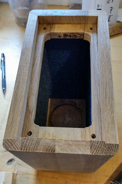
There's currently no rebate on the rear of the front baffle - something I'd usually do. I may add a shallow one to just help the seal to the box when glueing. This would reduce the internal volume slightly, but I've allowed for it in the cabinet depth.

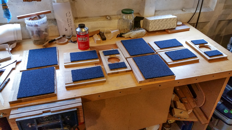
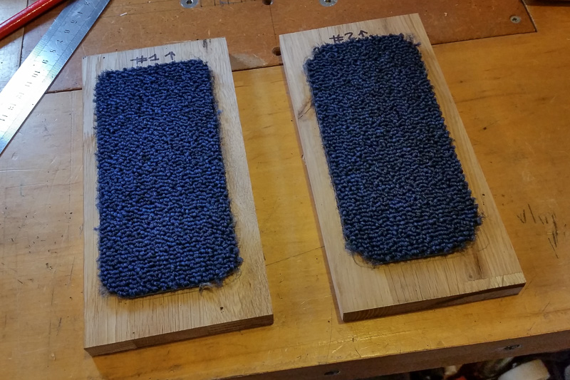
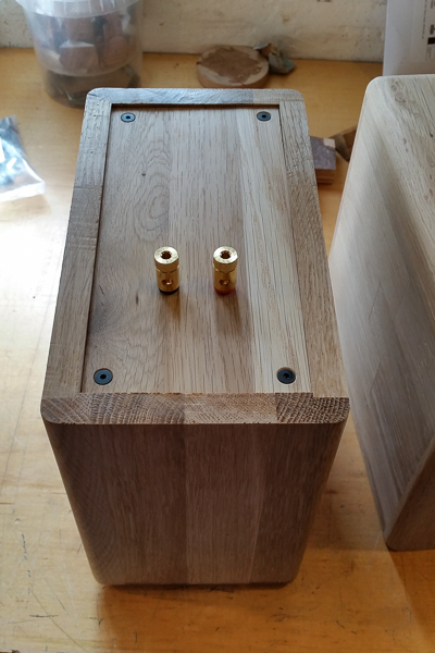
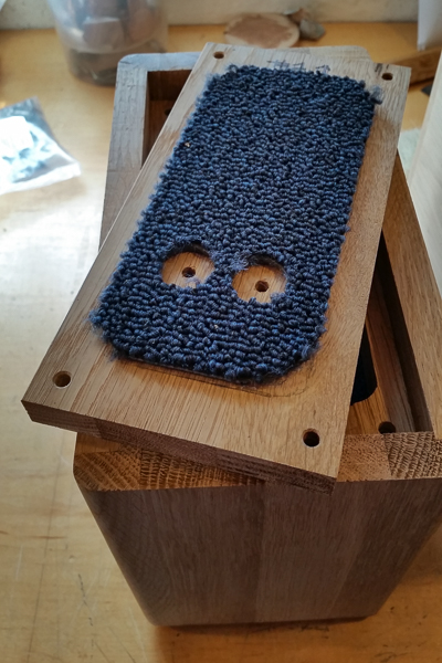
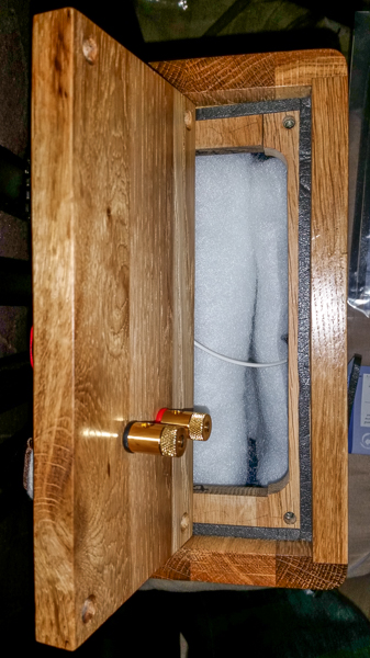
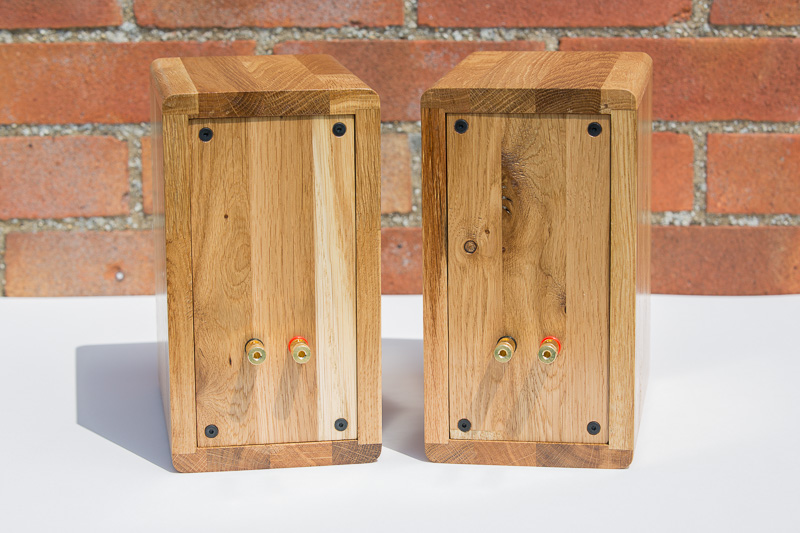
Lots still to do - fixing some dampening material to the insides, cutting the rear panels (and making some fixings so they can be removed), glueing, trimming, roundovers, finishing. It may be a while before I get time to progress them but I'll post again when I do.

On a final note: solid wood and loudspeaker cabinets isn't actually a great combination (wood movement vs the need for no air leaks); hence the reason boxes are usually constructed from man made boards, and painted or veneered. With luck I'll get away with it on these boxes, as they're pretty small.
 
Interesting project, bravo for trying it out with solid wood worktop off cuts. At least you know what is likely to happen :)


Sent from my iPhone using Tapatalk
 
Wuffles":3d0mxzc8 said:
Interesting project, bravo for trying it out with solid wood worktop off cuts. At least you know what is likely to happen :)
Well, I've made speakers from just about everything else: MDF, plywood, concrete, casting resin; so I suppose real wood is next (maybe fibre glass and/or carbon fibre one day :wink:)
 
I don't understand why you used a CNC to cut a jig to cut the holes. Why not directly use the CNC to cut the holes?

BugBear
 
bugbear":3367uwri said:
I don't understand why you used a CNC to cut a jig to cut the holes. Why not directly use the CNC to cut the holes?

BugBear

I'd take a punt that the CNC router is a 1/4" (ish) and that's not going to get through kitchen worktops, bearing guided bit on the actual heavy wood instead with a 1/2" router would be the only method.

Just a guess.
 
Wuffles":18k5191w said:
bugbear":18k5191w said:
I don't understand why you used a CNC to cut a jig to cut the holes. Why not directly use the CNC to cut the holes?
I'd take a punt that the CNC router is a 1/4" (ish) and that's not going to get through kitchen worktops, bearing guided bit on the actual heavy wood instead with a 1/2" router would be the only method.

Just a guess.
In short: balance of risk and effort.

The CNC machine has a 39x25" working area (in practice approx 990x610mm). With a Porter Cable 892 router it's quite capable of using large or long bits and chomping through material (I've carved boxes from 2" thick purple heart in the past).

However, it's best when you can just lob sheet material onto the table - then you'd cut all the panels, rebates, dados, holes etc in one go. Because I'm effectively working from scrap I couldn't afford to lose a part, and clamping a small sheet to the table and ensuring millimetre accuracy (getting the CNC to cut the hole in the centre of the panel) is more of a hassle than you'd think. And, albeit very rarely, the CNC will trip out during a cut (again risking losing that part).

It's also much easier to design a simple cut out jig in CAD than the "proper" cut out on the actual part; for one, you really need to add tabs, and then spend time removing them afterwards, as you really don't want the cut out from a circle coming free with the router moving over it; it can catch in the dust shoe, and, Things Go Bad(TM).

In short: the CNC is great when you can do a large cut out job on a sheet, or when you're cutting lots of identical parts, and when you can afford a mistake (an error in your design, or a part moving on the clamps). For cutting out two circles on small parts that you can't afford to screw up, it can be better to just create a jig and then do it by hand.

Also, I wasn't quite sure what the right hole + rebate size would be for the driver flange (in theory, 71 and 90mm respectively; in practice 71.5 and 90.5mm worked better). If you're doing that on the CNC then you have to design multiple "jobs" and test them, before running the right job. Again, it was quicker to just cut a few simple circles in a scrap of MDF and use it as a template.

So - no absolute reason why it couldn't have been done on the CNC, but on balance of risk I went for the template route. With a nice big sheet of oak I'd have CNC'd away :wink:
 
Wuffles":1cakrk6f said:
I'll get my d̶e̶e̶r̶s̶t̶a̶l̶k̶e̶r̶ coat...
:D

You can (within reason) cut just about anything with just about anything; e.g. even a small (underpowered) router would allow the use of a 1/4" bit with shallow passes. Generally with hobby/enthusiast CNC machines the combination of the machine rigidity and spindle horsepower means you're generally spinning the cutter too fast for the feed rates you can achieve. I can do a 1/4" deep cut with a 1/4" diameter spiral upcut bit at approx 2 inches per second in MDF, but I'd usually go for 1/8" depth with a 1/2" diameter bit. You don't want to slow the feed rate down too much otherwise you risk heat build up.

A "proper" machine may have something in the order of a 7hp spindle, and cut 3/4" deep in a single pass with a 1/2" cutter - at 7 inches per second. The spindle and tool change head would weight more than my entire machine though :wink:.
 
Some progress. I used offcuts to create the supports for the removable rear panels. The strips were wider than I wanted (wasting internal volume) so I clamped them together in pairs and drilled out using a forstner bit:

20160420_122833.jpg


I then trimmed out the material with the bandsaw, and did a quick clean up with a spokeshave (more on these later):

20160420_142154.jpg


I did decide to rebate the front panels - more to aid alignment when glueing than for strength, but also because I felt that the front panels looked slightly better with the visible edges a couple of mm thinner:

20160422_144348.jpg


I've had reasonable success in the past tapping hardwood, and lacking any 3mm Tee or insert nuts, I decided to tap the 3mm holes for the drivers - it worked well:

20160422_151057.jpg


Here are the front/top/bottom and side parts from both speakers:

20160422_152950.jpg


Part of the job of a speaker enclosure is to absorb the rear wave from the back of the driver (otherwise it tends to cancel out the wave from the front). In doing that, you really don't want the box ringing or rattling, so it's common to use (sometimes expensive) limp mass membrane material on the inside of the panels. Some of these products have a heavy rubber matting with a lightweight foam bonded to the top. Alternatively, if you're doing things on the cheap, it's called carpet tile. Break out the evo-stick:

20160422_155607.jpg


Once the boxes were glued, I trimmed the overhangs on the router table with a trimming bit:

20160423_153130.jpg


The top and bottom edges were then rounded with a 3/8" (9.5mm) roundover, and the front with 1/2" (12.7mm):

20160423_164959.jpg


At this point, I realised I'd screwed up; note how the pattern of the wood matches on the top and front of the right box... and it doesn't on the box on the left #-o . Looking back over my photos I must have screwed up fairly early with mixing up the ordering of the panels, so I got it wrong on one. Not the end of the world, but pretty annoying given that I chose the remaining worktop parts in order to squeeze the top/front/bottom out of a single sheet - specifically in order that they'd match up :oops:


The rear panel supports were drilled and fitted with 4mm insert nuts, and then glued in:

20160424_164812.jpg


After trimming the rear panels to fit, they drop in nicely (the recess is intentional - there will be a gasket around the back, but I'm hoping there will still be a small recess for aesthetic reasons):

20160424_171040.jpg


The rear panels also get the hi-tech absorption material:

20160424_172437.jpg


Next I need to drill the holes in the rear panels in order to screw them to the boxes, drill for the terminal posts, a bit of sanding and filling some small gaps, and then do the finishing.
 
I was going to ask about the design and fitting of the cross over circuit. :D

And then I decided not to. :oops:

BugBear
 
bugbear":1cjf2c50 said:
I was going to ask about the design and fitting of the cross over circuit. :D

And then I decided not to. :oops:

BugBear
*LOL* Actually it's a valid question on two fronts: there is a suggested filter (to shape the driver response slightly) but the design also suggests pairing the speakers with a sub, as they tend to distort when playing low frequencies.

In the kitchen system I'd admit I've used neither, but then they're shoved on their sides on top of cabinets - and that close to the ceiling is a recipe for comb filtering, so that's going to hit the sound quality way harder.

I'd suggest that a set of 5 or 7 of these (with their filters) and a DIY 10" Peerless XLS sub would make a very impressive little home theatre setup. From 3/4" MDF, you could probably build all of that for well under £200 (excluding the cost of an AV receiver and a sub amp, of course).
 
They look excellent. Hope they sound as good.

I built some LS3A speakers many moons ago and after all my hard work, my little nephew poked his fingers through the cones and soft domed tweeters.

Could have killed him. I didn't of course and now he is all grown up with kids of his own wrecking his stuff. Poetic justice.
 
Nice work - I never finished completely these Lowthers but they sounded great:

c2c5804924c89e3134bb25ccbf86870f.jpg

Shown next to some Leak Sandwiches:
947e95fa7df5dd4fe41c55afcb947ad7.jpg

e81e7b80ea2321f821e8d1dfa1cfc6fa.jpg


Both not very room friendly :)

Rod
 
skipdiver":1lf100mu said:
They look excellent. Hope they sound as good.
They should end up pretty decent. Obviously with a 3" full range system and no sub you're not going to get Earth-shattering quality, but they're pretty good for the size and cost.

skipdiver":1lf100mu said:
I built some LS3A speakers many moons ago and after all my hard work, my little nephew poked his fingers through the cones and soft domed tweeters.

Could have killed him. I didn't of course and now he is all grown up with kids of his own wrecking his stuff. Poetic justice.
Ah yea; with a toddler in the house now the covers have gone on the main speakers in the living room. I don't fancy fingers (or worse, something sharper) going though a ScanSpeak 21W/8554 or D2905/950000. Not least because those nice kevlar midbass drivers are discontinued!


Harbo":1lf100mu said:
Nice work - I never finished completely these Lowthers but they sounded great:
That's so often the problem with DIY speakers: get 'em working; job done. There's always more tweaks or finishes you could do, but the temptation just to listen to them often wins.

I have a "prototype" dual 10" sub tucked away in the living room (in use) that's a tatty MDF box. Obviously the plan was to create something nicer, but it's been there nearly 10 years now :wink:
 
More updates...

I put some dome headed bolts into the rear insert nuts and fitted the rear panels. A gentle tap with the "persuader" resulted in marks that would tell me where to drill the holes:

20160426_165854.jpg


I then drilled the holes for the terminal posts, and did a test fit:

20160429_114110.jpg


The terminal posts have a threaded rod that goes through the panel, and some nuts to hold them from the inside. Hence it's a good idea to remove some of the rear panel deadening material before glueing it on:

20160429_115526.jpg


Prior experience tells me it's a good idea to get a really smooth finish before using Danish Oil. I went from 180 to 240, 320, 400, and then gave them a final polish with a sanding pad (that happened to be around 1000 grit):

20160429_153237.jpg


The first coat justified that sanding work (it looks much better than the photo):

20160429_154919.jpg


I had a suspicion that the oil would darken the end grain more, so the fact that one box has mismatching grain isn't such a big deal. Here's the one that does match - but it still looks different on the front and top:

20160429_154946.jpg


The second coat went on this evening:

20160429_210340.jpg


I was then going to shellac and wax, but I'm really liking the look so far, and maybe the shiny result from shellac + wax wouldn't be such a good idea. I'll see what they look like tomorrow and I'll make a decision.
 
And so, we're done...

It took a good week or so for the danish oil to harden (you could feel the coating was slightly "plastic" for the first few days).

I had a bit of a faff doing the crossover/filter as I was a bit pushed for space. In the end I made it as a board that screwed onto the removable rear panel.

Speaker gasket installed, back loosely fitted, and leads ready for connecting to drivers:

20160513_105436.jpg


I was going to use some terminal connectors for the driver, but the ones I had weren't right, so I ended up soldering the leads on. At that point I realised I'd forgotten to put on the rear gasket. The leads are (deliberately) long enough to allow me to remove the rear panel, but I probably should have made them a bit longer. This was resting it on a cushion to install the gasket, and also having put in some stuffing:

20160513_115119.jpg


And finally, the "bling" shots:

IMG_0549.jpg


IMG_0552.jpg


IMG_0555.jpg


IMG_0557.jpg


IMG_0566.jpg
 
Love these speakers, something about engineered cones in an organic frame like wood that makes such an intriguing contrast. On my to do list now - I have a pair of bookshelf tannoys, and revolver colts that could become donors. How do they sound compared to before you made the new cabinets?
 
Helvetica":3hzloqgj said:
Love these speakers, something about engineered cones in an organic frame like wood that makes such an intriguing contrast. On my to do list now - I have a pair of bookshelf tannoys, and revolver colts that could become donors. How do they sound compared to before you made the new cabinets?
They are very impressive sounding for the price - though the original prototypes didn't have the filter (it's not a crossover as such as there's only one driver, but the circuit controls a breakup node and baffle step compensation).

Realistically, there will be no audible difference as long as the construction material is dense and doesn't rattle or resonate. A big problem with cheap plywood is voids and loose particles; which can buzz.

Solid wood isn't really the right thing to use for a speaker enclosure, as it'll move (and therefore affect the box seal). However, for such a small item I decided I could wing it.
 
Back
Top