Roubo bench project - WIP (UPDATE No 3 )

UKworkshop.co.uk

Help Support UKworkshop.co.uk:

This site may earn a commission from merchant affiliate links, including eBay, Amazon, and others.
Hello fellas,

I feel bad that I have not got round to posting an update on the Roubo bench project which is finished. :oops:

I have lots more pics of the build from the point above and promise to finish this thread, for the record.

My efforts to create a leg and wagon vice (based on the benchcrafted design) have worked, although I need to do some more work on the leg vice which is not quite providing enough clamping pressure.

I also must organise some pictures of my workshop which is pretty much completed, and in a bit of a messy state at the moment. I am going to have a tidy up over the Christmas holiday.

Thanks for continuing to show an interest in my efforts.

Cheers, Tony.
 
I've been checking daily for updates to this thread, and then we get a little teaser saying it is finished; but, you can't see it yet! :wink:

...oh well I'll keep on checking daily then.

DT
 
Well fellas here is a further, much anticipated, instalment on the Roubo bench project, work undertaken last spring and summer.

Picking up the thread from the previous post;

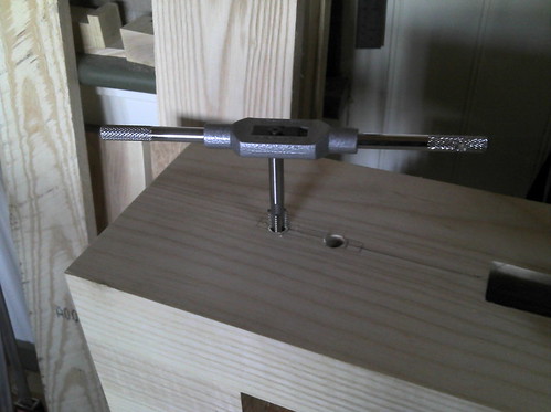
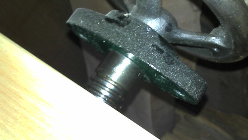
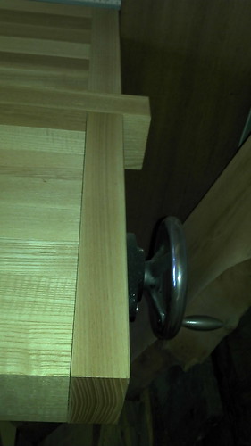
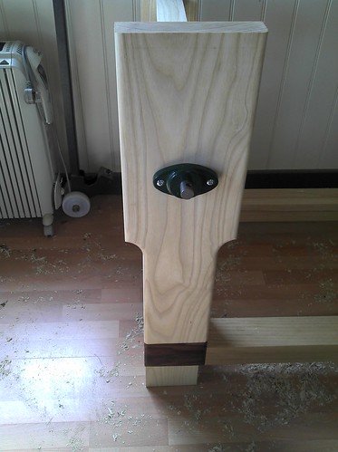
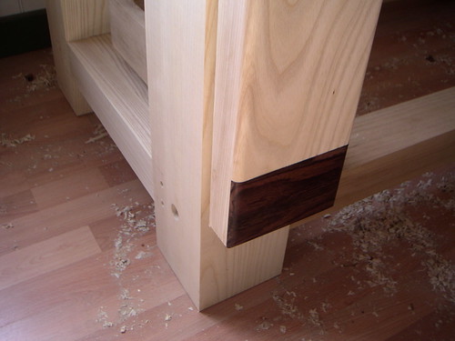
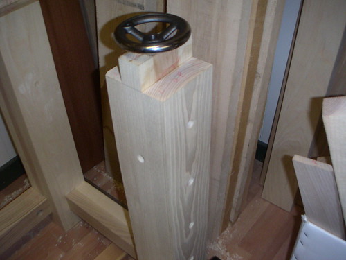
I completed work on the leg vice front inlaying a piece of Rosewood at the bottom to cover the tenon for the guide, here is a picture of the leg vice in position. The leg vice was made to be a little taller than needed, final adjustments to be made once the top had been made.


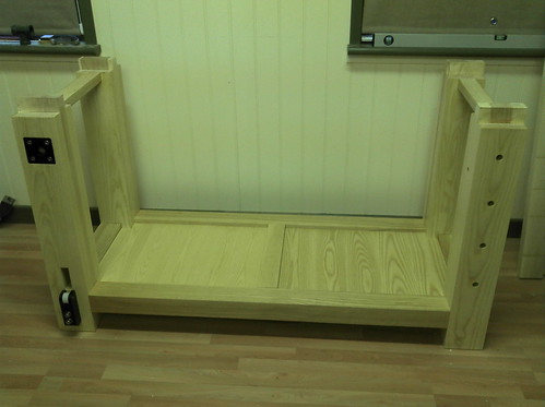
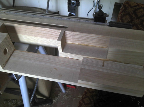
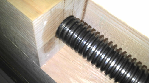
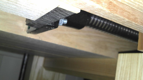
A view from the side which shows the legs glued at the sides and holes ready for two dowels, and the larger hole for the long bolt to hold the frame together, this approach means the bench can be knocked down if needed to be moved.


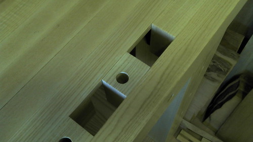
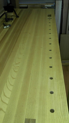
Here is a picture of the opposite side showing the leg with holes already drilled for dogs, holdfasts etc. You can also see a large hole in the long stretcher (bottom corner) this is for access to position the nut for the long bolt, coming from the other side.


It was a good strategy to drill holes and cut mortices etc before gluing the legs together. They were so heavy it would be difficult to manage this afterwards. Also if a boob was made a component could be remade without too much trouble.

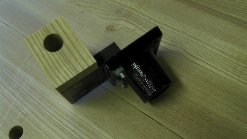
The frame was completed at this stage. Although, further work was required to complete the leg vice leg. The inlay of the acetal plate, and installation of the guide runners more on this later.

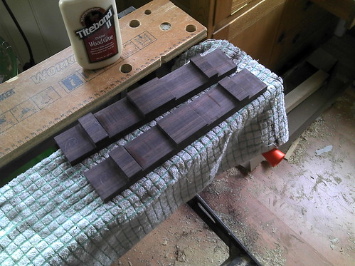
The next job was to start work on top. Here you can see the big job of splitting the 8" boards in half. Some of the boards were a little shy of this measurement and I seem to remember working to the smallest width which gave me 3 3/4" widths.

Here is a picture of the operation in progress using my trusty bandsaw.


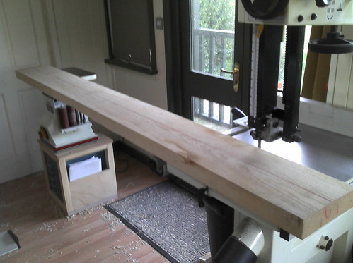
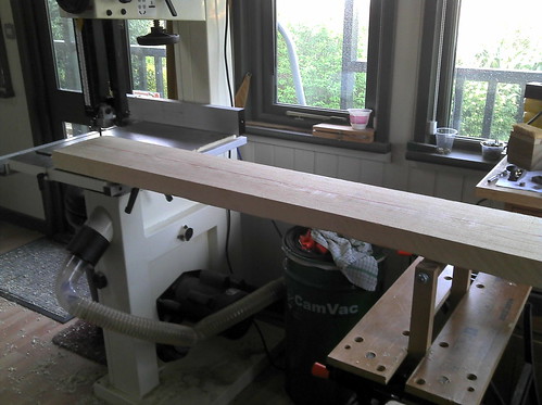
When I made the little stand for my bobbin sander I made sure the finished height matched that of my bandsaw. A very handy support for this job. I did not have a roller stand so made one which clamped into my workmate. This was also an effective solution on the outfeed side.

Once I had cut the boards I used my PT to square these up. I was not to worried about the thickness which varied a little from one length to the next. Although, it was important to ensure I had six pieces the same thickness as the leg laminations as this would make fitting the top easy. I selected the best pieces for the front and back and tried to match the grain where possible. Any grotty pieces were made good with a thick veneer. An approach I used earlier on the leg construction.

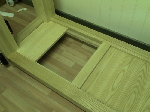
The width of the top was now just over 3 1/2" the lengths were odd but all 7ft +. Here is a first picture of the top coming together.


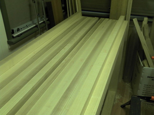
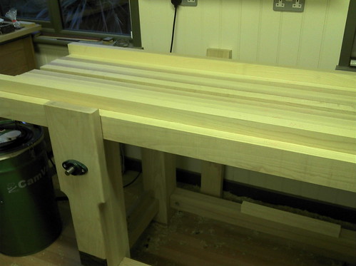
You can see two lengths sticking up in the above picture, well they were sitting on the leg mortices. The next job was to cut the mortices for these. Very easy as the thicknesses were the same just a simple cut out on the bandsaw.

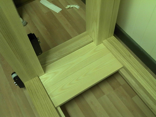
I had plans for a stop near the leg vice and this was easy to create just by cutting a length and leaving a gap when gluing together.


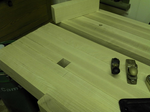
I glued the top together in stages. Glue everywhere, the most nerve racking part trying to get all the clamps on and keep things level. I decided at this stage to keep the top in four sections, approx width 8". This meant I could run the glued board through the PT and also meant I could handle lifting these heavy chunks around. The picture above shows a gap in the top this was to accommodate a removable section. An idea I had seen on one of Richard Maguire's benches.

The removable piece enables clamps to be passed through the top for clamping and also to create a long stop the length of the bench, another useful feature.

Here is a good place to stop on update number two. More to follow, including;

The fitting of the bottom shelf.
The issues with the wagon vice. leg and top.
The metalwork for the vice screws and wheels.
Making the little guides for the leg vice and fitting the acetal plate.

Thanks for continued interest. If I can be of any help with my experience of making this bench please give me a shout.

Cheers, Tony.
 
Tony,

Brilliant WIP. I am just looking at the options for handwheels for a leg vice- I much prefer them to the "normal" wooden handles. Was it a big job to reduce the diameter of the screws to fit your wheels? 8" wheels seem less readily available. There are some 5" ones on ebay at the moment which seem like sensible money, but will need a bit of modifying. This should do for a wagon vice. I would also like to make a moxon vice, based on the benchcrafted one whilst I am at it, but that would involve tapping 2 of the 5"- at least the wagon vice does not seem to require that being done. How come did you have to tap the handwheels?

TIA
Mark
 
Hello Mark,

I used Veritas vice screw threads for both the leg and wagon vices on my bench. The diameter of the screws were too large to fit both handwheel centre holes and I looked everywhere for handwheels the correct size, to no avail. The job of reducing the diameter was beyond my skills or nerve on my little metal working lathe so I out sourced this job to my engineering mate.

I would recommend this approach, if you can find a little engineering shop. On a big lathe with the skills it is an easy job. It is also very important for the wheel to accurately fit the screw. The wheels were simply pressed on to the screws with some sort of heavy pressing machine.

I have plans to take some more pictures for this thread of the wagon vice set-up, including a bit of commentary on the above.

One small issue worth mentioning with regard to the diameter of the smaller wagon vice wheel. My bench has a 3 1/2" thick top and as I centered the screw in the top of bench end the wheel at 5" diameter just protrudes above the bench top. An issue I completely overlooked. It is a small point, but as the wagon vice only travels 6" I would go for a smaller wheel with a diameter of less than the bench top thickness. I couldn't fit the vice any lower in to the top due to the position of the leg!

Hope these comments help. I must organise a few more pictures to supplement those I already have to explain matters.

Cheers for now. Tony.
 
Looks really good! Is the top going to feature any dog holes? If you go for drilled holes I really recomend Richard T's holdfasts, they're fantastic!
 
Hello fellas, here is a further update to this thread.

Mark, I have included some pictures of the wagon vice set-up, and Andy you might just spot one of Richard's holdfast sitting in a dog hole keep a look out.

Firstly, I would like to show some pictures of the shelf I fitted to the bottom of the bench. It was just easier to make and fit this before continuing with work on the top.


Using some offcuts I simply screwed some batons inside the stretchers, it was easy to cut and fit some planks to sit nicely on these batons. The picture also shows the two brackets I made to support the leg vice guide. More on this later.

To provide more support and structural strength to the long stretchers I fitted a piece in the middle glued with two large dominos in each end. That domino machine really is excellent. It is also very handy to have a little person to crawl around and do the fitting. Young Tom in action


In this picture you can see the bench frame completed, notice the acetal plate fitted in the leg vice leg to support the screw, held in place with some cap head bolts.


Here is a picture showing my approach to making the two leg guide brackets.


I made the pair from one piece of timber. It was easy to cut the space for the little nylon wheel and mortice for the bolts using my bandsaw, then gluing the two sides back together. The wheel held in place with a small metal rod.

Here you can see an action shot of tapping the leg for the cap head bolts


Now back to the top and in particular the wagon vice

This picture shows the cuts I made in the underside of the top to fit the wagon vice, all were made before gluing up. I didn't have a plan only figured out where I need spaces for the mechanism to work. I could also clamp and hold the top together and dry fit the screw to test and refine matters before gluing all together. A bit of trial and error.


You can see in the picture three sections which make up the front apron of the bench top. The furthest section away is the underside of the front of the bench. I cut a groove in this with my router while I had the chance, as I thought it might come in handy if at a later stage I wanted to make a sliding deadman.

The middle section shows the mortise which fits onto the tenon on the leg. I wanted to install the wagon vice as far into the bench as possible, and to the left of the right front leg. I thought it would be better to maintain the strength from keeping this mortice intact, a major part of holding and locating the top in place. The gap to the left is where the vice dog moves.

The front section shows the cut away for the screw to sit in. The hole on the left houses the end of the screw.

Here is a picture of the vice component.


I used a piece of the acetal plate to attach the vice to the bracket which came with the vice screw. This is simply bolted and screwed together.

The vice screw is bolted to a bread board type (I think that is the right term) end piece. The screw passes through this and locates in the hole.


Here you can see the small handwheel and the sleeve made to fit the wheel. This work was carried out by my mate who has a small light engineering shop. The screw thread had to be reduced to fit the wheel. The screw was simply pressed on to the wheel using a heavy press.

Here you can see the screw located into the hole. This stays in place as it is attached to the end of the bench and cannot move.


Here a view from the top, all in place


Hope this instalment is of interest, keep watching still a bit more to come.

Cheers, Tony.

PS - here are a few more pictures which may add to the above commentary;


Tony,

How much Acetal did you use on the leg vice- something like 2 1/2" square?

Cheers
Mark
 
Tony...

You keep setting the 'Benchmark' here (Excuse the pun) :mrgreen:
I am making a smaller 5' 6" version in pine, and I think I'll reconsider my intention to post a WIP. Either that, or up my game!

Smooth work indeed. You have to be inspired with a bench like that.

Nice one.

Regards
John :D
 
Nice looking bench! A few questions:

- Do you find that acetal plate is helpful? Necessary? Bottom rollers should hold up the leg on their own. What is the function of the plate? To relieve just a bit of pressure from nut so weight of the screw wouldn't be resting on bottom of the nut, to give you less friction while turning the crew? Was it hard to balance the plate it so it isn't carrying too much or too little weight?
- What diameter was required for hand wheel bore?
- Perhaps I missed it, but how are you securing the top to legs, aside from M&T? I am considering knockdown bench that will allow me to also pick it up by the top so it can be moved around the shop. My thinking is unglued M&T plus a 1/2" bolt through the top on each leg.
 
Thanks fellas for the kind comments.

To respond to a few points raised;

Chems, I agree with your thought in away. I do think twice about drilling into the bench or wacking it with my hammer, and have a mat for my coffee mug! :oops: Although, as the bench gets used, I suppose it will age nicely with the scars and wounds from honest use. I also think that making a bench is a sort of right of passage. It's a bit like Waka's lovely tool cabinet. Overkill, probably but an opportunity to learn a few new skills and to tackle something big. The construction is fairly basic joinery.

I have another bench in my workshop which I made with an mdf top, just like Paul's, and my old bench had this. An excellent choice of material, easy, simple and can be replaced from time to time. Just as serviceable as my solid Ash top and I suppose a fraction of the cost and effort.

Mark, I think the acetal plate is about 3" square. It is an 18mm piece. I used my router with a bearing guided cutter and made a little jig witch I clamped to the leg to accurately remove the timber to inlay this, held in place with four cap head bolts tapped into the leg.

John, I look forward to seeing your bench. I am sure you can keep up the standard!

Addendum. Welcome to the forum, I see this is your first post.
The jury is still out on the acetal plate. I must confess, I took the idea from the benchcrafted leg vice kit. I think the purpose is to help align and centre the screw which passes through the five inch leg. In order for this to run smoothly it is important for the screw not to touch the inside of the leg. Careful tweaking of the plate helps to set this up. It seems to work as I have the vice moving very freely.

You definitely need both guides top and bottom as this helps to support the guide which also passes through the leg. Again, it is important for a smooth action that the guide does not touch the inside of the leg. The leg mortise for this is a little oversize, but not enough to make the leg vice too sloppy (wiggle from side to side too much).
The roller guides also help to support the vice and take the strain from the screw. All help to ensure a smooth action.

The guide is very important as this helps to stop the vice racking. The holes in the guide are used with a pin or screwdriver to roughly keep the vice open at approximately the thickness of the timber being clamped, this allows much more pressure to be applied to clamp the item. The two roller guides also seem to take up some of the strain in holding the vice in place.

It is not to difficult to set-up. Once I had the vice in place I fitted the bottom roller guide pushing the vice up so it did not to touch the inside of the leg mortise making sure the screw was running smoothly. I then fitted the top roller pushing down to square the vice up. The aim to get the guide running on both rollers and not touching the inside of the leg. It sounds difficult, but was made easy as I could slide the roller guides up and down to get the best fit and bolt this in place once in position.

The bench top is in five pieces and can easily be knocked down. It is enough to carry one of these on your own.The top simply sits on the leg tenons, the weight holds the top in place, it cannot move in any direction. You should not need to use the bolts you mention.

I have one more update to make on this thread. I will provide a bit more commentary on the leg vice.

The vice is not quite perfect yet, I am mulling over fitting a crochet to the front and may also line the inside with some suede to see if this helps with holding items tightly

Hope the above comments are helpful.

Cheers, Tony.
 
Escudo":xqen6vl6 said:
The top simply sits on the leg tenons, the weight holds the top in place, it cannot move in any direction. You should not need to use the bolts you mention.

I have one more update to make on this thread. I will provide a bit more commentary on the leg vice.

The vice is not quite perfect yet, I am mulling over fitting a crochet to the front and may also line the inside with some suede to see if this helps with holding items tightly

Hope the above comments are helpful.

Cheers, Tony.

Thank you, Tony, these details are very useful. In my case, I need to have access to some storage that is between my bench and the wall, so it will be necessary to move the bench away from the wall by a foot or two once every few weeks. This is why I want bolts, so bench top can be lifted (and bench with it) and dragged around my workshop. I guess I could try to grab it around a leg and drag it around like that, but not sure I'd have a comfortable enough grip for the weight.

Please also remember to tell us diameter of LV screw where hand wheel goes, if you have it recorded. I have not been able to find this information anywhere, and I don't have the screw yet.
 
Addendum,

I just found the email reply from Veritas when I enquired about the screw thread diameter. I will check the diameter of the forstner bit I used, can't remember if this was 28mm or 30mm.

Thank you for contacting Veritas Tools Inc.

The main screws are metric screw threads, the specification is Tr 28 X 5 in accordance with DIN 103 (ISO 2903) with the major diameter restricted to between 27.665-27.800 mm.

Hope this helps.

Regards,
George Hammond
Customer Service

I have been able, with some effort, to drag my bench away from the wall, the top lifts a little but cannot come away if you move from one end to the other in a tacking motion. My floor is quite smooth which helps.

When I made the laminations for the legs I carefully noted the thickness of the middle section (the tenon) and made sure the lamination of the top matched so my mortise fitted tightly. It cannot move north to south or west to east and has to be removed from the middle, straight-up even lift.

Good luck with your bench, hope you will make a WIP. It is time consuming, but worthwhile and rewarding to document construction for the record.

Cheers, Tony.
 
Escudo":1hjsat9w said:
The main screws are metric screw threads, the specification is Tr 28 X 5 in accordance with DIN 103 (ISO 2903) with the major diameter restricted to between 27.665-27.800 mm.

I wasn't clear - what I mean is not the threaded part, but the end of it where it goes into the... thing that accepts wooden handle - I am assuming that end is not threaded and that it is smaller diameter than the threaded part. If this is to be replaced with a hand wheel, I wanted to know what would be diameter of opening required in the hand wheel so it could be mounted (that is, I want to further explore the option of getting a large enough hand wheel to fit, or perhaps even make one out of wood+metal).
 
I am with it, although I am not sure I know the answer. I am sure the end did not have a thread part. I think it was the same diameter. I had to have the screw machined down at the end to fit the diameter of the hole in the hand wheel.

This will vary depending on your wheel. If you could make a wheel, it maybe best to wait until you get the screw.

Lee Valley are very helpful you could always send them an email.

Tony.
 
worth also noting that it is advised to use cast iron wheels, because their mass helps to move the vice in. I am not sure where I read this, possibly benchcrafted, possibly elsewhere.
 
Back
Top