siggy_7
Full time tool collector, part time woodworker
Well after further deliberation and an appearance of the purchase monster, I decided to go for the Record TS250-RS after all. I bought one from Yandles at the recent Record Power show, including Squaring Table, Wheel kit and Mitre fence, along with a DX4000 and accessory kit. The saw and accessories were delivered the following Friday, the extractor was out of stock and came separately 12 days later.
I set aside quite a bit of time for assembly, knowing that it wouldn’t be a 5 minute job – and so it proved. The instructions aren’t terrible but aren’t perfect either, there are a few omissions and mistakes which I hope to save other people the hassle from in this review. I received a total of 7 packages with my saw order, which came in polystyrene insert packaging to keep everything nice and secure during transit.
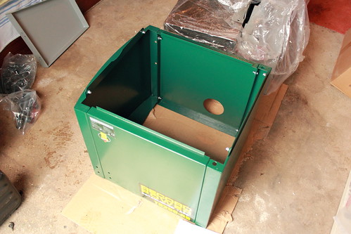
The first assembly step is to assemble the base for the cabinet. The four sides bolt together, and I was surprised at the amount of adjustment in the holes. My recommendation would be to set the front and back panels so that the tops sit slightly lower than the sides, and also to set them back slightly so that the tops of the front and back panels are slightly closer together than you might think. It doesn’t need to be much, but I found that when fitting the saw unit on (which attaches via two bolt holes on each side piece) I had to reach inside the cabinet to slacken off some of the bolts and make adjustments – not ideal! I added on the swinging outrigger arm at this point because I have that option. The outrigger feels quite solid and slides without any play. It also has a magnet that holds it against the cabinet when not in use, a nice touch.
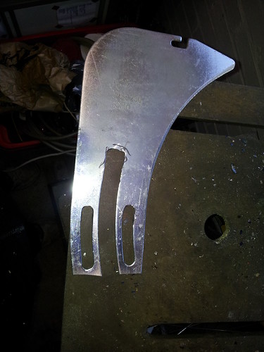
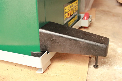
There is a base stabiliser which attaches to the front; the written instructions mention that you need to screw this in with 4 hex-head M8 bolts but it’s obvious you need to do so. There is an M10 bolt that attaches to the underside of the stabiliser which serves the purpose of levelling the unit on uneven ground; where the manual says “M10 bolt and washer” it actually means the bolt and a nut for locking it in place. As I had the wheel stand, there was a longer bolt included in the box for that accessory.
I next put the assembled cabinet on the wheel stand before lifting on the saw unit. Obvious to most people I hope, but I wouldn’t put it past myself to not have rushed into it without thinking and then had to lift the much heavier fully assembled unit on as a result. The wheel stand is a welded frame which has two fixed wheels and two non-adjusting skids on the other side and a cut-out for the base stabiliser. A twin jockey wheel inserts in the other side and lifts the two skids off the ground, which works well and I found surprisingly manoeuvrable and capable of going over my tamped concrete drive easily, which I was prior a bit worried about. The wheels are arranged with the fixed wheels on the right of the saw, and the jockey wheel fits to the sliding beam side of the saw on the left, so you move the saw right-left in a straight line, rather than forward-back as I was expecting.
Lifting the saw unit on is definitely a two person job, but not actually as bad as I was expecting – I managed to do it with my Mum quite easily, she’s very small and I’m no beefcake, so two reasonably able adults should be able to handle it. The manual states that you should attach the saw with 4 M8 allen head bolts, but the threaded inserts on mine were M6 which caused some initial confusion – fortunately there were M6 bolts supplied for the purpose!
The hand wheels are solid cast, and I had two different wheels (the grub screws were different sizes) although the manual states that they are identical. The smaller grub screw wheel I attached to the angle adjuster; the grub screw fits into a keyed slot. The larger grub screw wheel I fitted to the rise and fall shaft, which has a machined flat for the grub screw to engage onto. The grub screws require quite a long handled allen key to tighten, which wasn’t supplied – fortunately I had ones that fitted (the saw was supplied with a 10,13 and 16mm spanner as well as two allen keys for the M6 and M8 bolts).
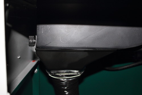
The NVR switch is stored within the saw for safety during transport, and is easily retrieved from within by opening up the access hatch on the left hand side. Whilst this was open I also dropped down the hose for the internal dust extraction and had a good poke about. The extraction system has a plastic shroud around the blade which is extracted via a 100mm flexible hose. This looks fairly decent and I am hoping will give good extraction, although only some use will tell. Picture of the internal shroud, taken through the side access hole:
The threads on the rise/fall and angle screws are rolled threads and engage with metal teeth on the trunnions, which have a solid and smooth feel. Everything was nicely greased and the table was covered in a protective anti-rust oil as well.
There is a plastic component that looks like it should push into the back of the saw for the dust extraction system, so that’s what I did with it (no mention or sign of it in the manual). It was a tight fit to push in, but engaged nicely once done. The 100mm flexible hose passes out through this, then a large jubilee clip attaches to another solid plastic coupling to link up to a 100mm extraction hose, and also has a 30mm port to connect to the crown guard extractor. A 30mm hose is supplied to connect this up. The crown guard is a standard plastic affair that attaches to the riving knife with a knurled fastener, which will be replaced at some point on my saw with an overhead guard which will allow me to cut down the riving knife for part-depth cuts.
It was at this point that I found that a few small bits for installing the sliding beam were missing from my kit! I called Yandles to ask them to sort the problem out, as it was a Saturday I had to wait until the following week for Record to resolve the issue. These things happen I guess and to be fair to Record they called me the day the fault was reported to them and the parts were with me the following day. If I’m honest I would have run out of time before completing assembly that day anyway, so no real harm done.
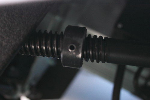
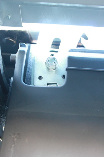
I took the time I had at this point to check a couple of alignments. The blade wasn’t at 90 degrees when against its stop, so I set that right. The stop engages on the rolled thread via a grub screw and is not a separate bolt on my saw as the manual suggests. This proved to be a bit of a faff to set up, as undoing the grub screw even slightly causes it to foul on the front trunnion. My solution was to slacken the grub screw off just enough to free the stop, set the blade at 90 degrees and then wind the stop hard up against its rest face. I couldn’t tighten the grub screw in this orientation, so I wound the stop back a quarter of a turn and locked it off, tilted the blade at an angle, then wound the stop forward the quarter of a turn again. I re-checked and all was fine. Picture of the stop, taken through the rise and fall slot:
I checked the run out on the blade with a dial test indicator, which was 7.5 thou – not super-great, but I consider that passable for the supplied blade (a 36 tooth multi-purpose). I plan to replace this with a 60 tooth ATB blade for general purpose duties soon (I don’t plan to rip much thick hardwood), either a Freud LP040 or an Atkinson-Walker Industrial one. When I do this, I will check the run-out on the arbour as well, but as the blade came attached I didn’t remove it just for this purpose. The riving knife has 2.3mm thickness stamped on it, which I measured as 2.34mm with a Vernier. The alignment needed some tweaking, which is achieved via three grub screws which are easily accessed through the side of the saw once the 16mm nut is slackened off a bit. Make sure you really tighten this nut back up again – when I was doing some trial cuts, I inadvertently hit the back of the riving knife with a board sliding the carriage back for another cut, and the knife sprung back onto the blade. Close-up on the riving knife adjustment:
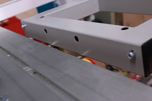
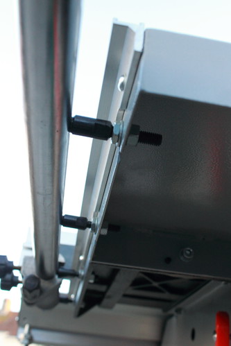
Fast forward two weekends and it was time to finish the assembly. The sliding beam is aluminium, which I am treating very carefully to avoid damaging it too much – the one on display in Yandles appears to have suffered a bit from being bashed about, but being built to an affordable price not everything can be solid precision ground cast. A small plate sits at either end of the saw on which the sliding beam rests, and is secured onto these plates via a bolt from the underside into a nut running in the slot on the underside of the beam. Two bolts on the underside of the beam align the beam front-back, and two bolts on the side of the saw act as stops to ensure a consistent parallel distance from the main table, although these bolts cannot be adjusted in situ. The sliding beam can be levelled by two grub screws underneath each of the small beam rest plates, which quickly got the whole thing levelled with the main table, and then clamped down nice and tight. The image below shows one of the plates in position at the back, and the slot where the second one will rest at the front, along with the levelling grub screws clearly visible:
The manual doesn’t mention the installation of the sliding beam lock, which I tackled next. This bolts onto the underside of the sliding beam, and once installed provides a simple lock to the sliding beam travel by sliding a sprung catch into a notch on the underside of the beam.
Next was the installation of the pressed steel extension tables. Two bolts fix the rear extension table, and four for the side extension table. There is some vertical travel in the holes on the extension tables, and grub screws also which provide the means for aligning the extensions to the main cast table. This didn’t take too long although was slightly fiddlier than I thought. Once these were on, I bolted the support for the crown guard extraction hose onto the side extension table.
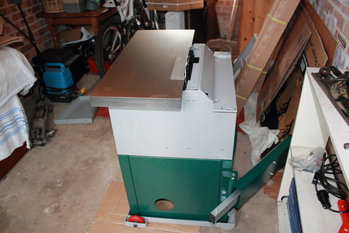
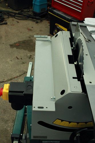
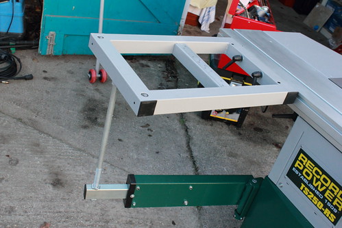
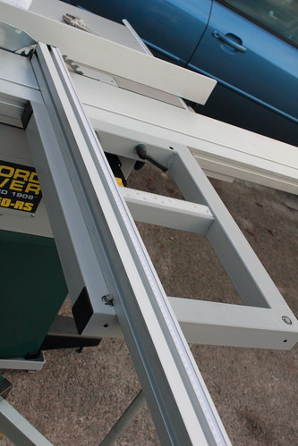
The scale and rip fence rail bolt on to the front of the cast table. The measuring scale has some horizontal movement, although it is at the limit of travel to one side at the moment and I think it needs to be further over still – I didn’t fully check this though so will check again soon. The rip fence rail attaches via four bolts with a nut either side of the table; some vertical adjustment in the slots sets the rail at the correct height and a nut either side of the cast table sets the rail so that the rip fence is parallel with the blade. The front mount is pretty solid and includes a micro-adjuster; I plan to get a magsquare to provide additional support to the back of the rip fence as with all non Biesemeyer-type fences only mounted on one rail the far end could do with a little extra support. It’s still reasonably solid though. The rip fence can be adjusted front-back to help prevent kickback when ripping, so no need for a separate short rip fence. The following two images show the compact size of the full saw assembled (minus squaring table) and the mounting of the rip fence rail.
I tried the mitre gauge in the slot. It doesn’t appear to slide when everything is tightened up – I need to investigate this some more, but it seems that the intention is that the mitre gauge is clamped in position on the sliding beam and then the beam travel is used to make the cut. It seems very solid in the slot when clamped down. Unlike in the brochure images, there is no hold-down clamp on the gauge.
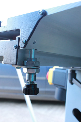
There is a slot in the side of the sliding beam that accepts a double bolt mount for the squaring frame table. A single rod screws into the underside of the squaring table, and a pair of nuts the other end secure the rod into the outrigger, and provides a height adjustment to level the table. The squaring table sat proud of the sliding beam when installed; I need to investigate a way of levelling this.
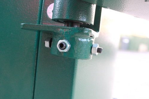
There was a loud clunking when I tested the complete assembly, which I traced to the outrigger pivot. There are four grub screws which require tightening up against the pivot; these obviously must be to align the pivot vertically. I just wound them in; I will check the proper alignment in the near future.
The cross-cut fence can attach to the squaring table in one of two positions; a pin sits in a hole on the squaring table about which the fence pivots. The pin sits in a slot on the underside of the fence so when cutting at an angle you can still ensure the fence supports the workpiece up close to the blade. The fence is clamped onto the table by a bolt and hand lever. For cutting at 90 degrees, there is a stop which pushes up from the squaring table to butt the fence up against (one at each end for each of the holes for the locating pin). This is eccentric, so the 90 degree position can be set correctly by undoing a grub screw and rotating the stop in its mount, then locking into position again with the grub screw. There is a flip-over stop for cross-cutting which runs in a slot on top of the fence, but no hold-down clamp. I plan to source one soon. There is a small support on the end of the fence for supporting long pieces, and the fence telescopes out to over 2m in length when needed.
After all this, all that remained was to screw on the crown guard and hook up the 30mm hose to the rear extraction point. And I was finished! I still need to re-check a few alignments, and I also need to check the beam and mitre slot are parallel to the blade – as the beam is aluminium, I can’t use a magnetic base for a dial test indicator. I plan to make up a simple jig riding in the mitre slot for this purpose.
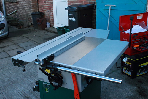
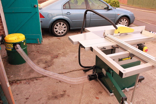
I hooked up the extractor and made a few trial cuts on 1” thick chipboard up to about 1m square, which I will be using to board up the workshop roof for storage of all the junk that’s currently in there. While obviously no test of cut quality, everything ran smoothly and there was no hint that this was really trying the load bearing capacity of the beam and sliding table. Dust extraction from the cabinet seemed good, although the crown guard extraction was not at all effective. I plan to replace the crown guard with a proper overhead style one at some point, and probably run this to a separate extractor as I don’t think the 30mm tee into the main extraction hose is providing sufficient suction. The one limitation I have found so far is that it appears that the outrigger travel does not extend far enough to allow a full 1220mm stroke on the sliding beam when the extension table is used. I didn’t have enough time to properly look into this before it started to get dark (my workshop lighting is currently terrible!) so I will add onto this thread as I get more experience with the saw. Overall though, I’m very pleased with it and think I made the right choice; with the squaring frame off it’s nice and compact for my small workshop but with it all set up it appears to have the capacity for working with quite large and heavy sheets accurately.
Final image of the complete set-up:
I set aside quite a bit of time for assembly, knowing that it wouldn’t be a 5 minute job – and so it proved. The instructions aren’t terrible but aren’t perfect either, there are a few omissions and mistakes which I hope to save other people the hassle from in this review. I received a total of 7 packages with my saw order, which came in polystyrene insert packaging to keep everything nice and secure during transit.
The first assembly step is to assemble the base for the cabinet. The four sides bolt together, and I was surprised at the amount of adjustment in the holes. My recommendation would be to set the front and back panels so that the tops sit slightly lower than the sides, and also to set them back slightly so that the tops of the front and back panels are slightly closer together than you might think. It doesn’t need to be much, but I found that when fitting the saw unit on (which attaches via two bolt holes on each side piece) I had to reach inside the cabinet to slacken off some of the bolts and make adjustments – not ideal! I added on the swinging outrigger arm at this point because I have that option. The outrigger feels quite solid and slides without any play. It also has a magnet that holds it against the cabinet when not in use, a nice touch.
There is a base stabiliser which attaches to the front; the written instructions mention that you need to screw this in with 4 hex-head M8 bolts but it’s obvious you need to do so. There is an M10 bolt that attaches to the underside of the stabiliser which serves the purpose of levelling the unit on uneven ground; where the manual says “M10 bolt and washer” it actually means the bolt and a nut for locking it in place. As I had the wheel stand, there was a longer bolt included in the box for that accessory.
I next put the assembled cabinet on the wheel stand before lifting on the saw unit. Obvious to most people I hope, but I wouldn’t put it past myself to not have rushed into it without thinking and then had to lift the much heavier fully assembled unit on as a result. The wheel stand is a welded frame which has two fixed wheels and two non-adjusting skids on the other side and a cut-out for the base stabiliser. A twin jockey wheel inserts in the other side and lifts the two skids off the ground, which works well and I found surprisingly manoeuvrable and capable of going over my tamped concrete drive easily, which I was prior a bit worried about. The wheels are arranged with the fixed wheels on the right of the saw, and the jockey wheel fits to the sliding beam side of the saw on the left, so you move the saw right-left in a straight line, rather than forward-back as I was expecting.
Lifting the saw unit on is definitely a two person job, but not actually as bad as I was expecting – I managed to do it with my Mum quite easily, she’s very small and I’m no beefcake, so two reasonably able adults should be able to handle it. The manual states that you should attach the saw with 4 M8 allen head bolts, but the threaded inserts on mine were M6 which caused some initial confusion – fortunately there were M6 bolts supplied for the purpose!
The hand wheels are solid cast, and I had two different wheels (the grub screws were different sizes) although the manual states that they are identical. The smaller grub screw wheel I attached to the angle adjuster; the grub screw fits into a keyed slot. The larger grub screw wheel I fitted to the rise and fall shaft, which has a machined flat for the grub screw to engage onto. The grub screws require quite a long handled allen key to tighten, which wasn’t supplied – fortunately I had ones that fitted (the saw was supplied with a 10,13 and 16mm spanner as well as two allen keys for the M6 and M8 bolts).
The NVR switch is stored within the saw for safety during transport, and is easily retrieved from within by opening up the access hatch on the left hand side. Whilst this was open I also dropped down the hose for the internal dust extraction and had a good poke about. The extraction system has a plastic shroud around the blade which is extracted via a 100mm flexible hose. This looks fairly decent and I am hoping will give good extraction, although only some use will tell. Picture of the internal shroud, taken through the side access hole:
The threads on the rise/fall and angle screws are rolled threads and engage with metal teeth on the trunnions, which have a solid and smooth feel. Everything was nicely greased and the table was covered in a protective anti-rust oil as well.
There is a plastic component that looks like it should push into the back of the saw for the dust extraction system, so that’s what I did with it (no mention or sign of it in the manual). It was a tight fit to push in, but engaged nicely once done. The 100mm flexible hose passes out through this, then a large jubilee clip attaches to another solid plastic coupling to link up to a 100mm extraction hose, and also has a 30mm port to connect to the crown guard extractor. A 30mm hose is supplied to connect this up. The crown guard is a standard plastic affair that attaches to the riving knife with a knurled fastener, which will be replaced at some point on my saw with an overhead guard which will allow me to cut down the riving knife for part-depth cuts.
It was at this point that I found that a few small bits for installing the sliding beam were missing from my kit! I called Yandles to ask them to sort the problem out, as it was a Saturday I had to wait until the following week for Record to resolve the issue. These things happen I guess and to be fair to Record they called me the day the fault was reported to them and the parts were with me the following day. If I’m honest I would have run out of time before completing assembly that day anyway, so no real harm done.
I took the time I had at this point to check a couple of alignments. The blade wasn’t at 90 degrees when against its stop, so I set that right. The stop engages on the rolled thread via a grub screw and is not a separate bolt on my saw as the manual suggests. This proved to be a bit of a faff to set up, as undoing the grub screw even slightly causes it to foul on the front trunnion. My solution was to slacken the grub screw off just enough to free the stop, set the blade at 90 degrees and then wind the stop hard up against its rest face. I couldn’t tighten the grub screw in this orientation, so I wound the stop back a quarter of a turn and locked it off, tilted the blade at an angle, then wound the stop forward the quarter of a turn again. I re-checked and all was fine. Picture of the stop, taken through the rise and fall slot:
I checked the run out on the blade with a dial test indicator, which was 7.5 thou – not super-great, but I consider that passable for the supplied blade (a 36 tooth multi-purpose). I plan to replace this with a 60 tooth ATB blade for general purpose duties soon (I don’t plan to rip much thick hardwood), either a Freud LP040 or an Atkinson-Walker Industrial one. When I do this, I will check the run-out on the arbour as well, but as the blade came attached I didn’t remove it just for this purpose. The riving knife has 2.3mm thickness stamped on it, which I measured as 2.34mm with a Vernier. The alignment needed some tweaking, which is achieved via three grub screws which are easily accessed through the side of the saw once the 16mm nut is slackened off a bit. Make sure you really tighten this nut back up again – when I was doing some trial cuts, I inadvertently hit the back of the riving knife with a board sliding the carriage back for another cut, and the knife sprung back onto the blade. Close-up on the riving knife adjustment:
Fast forward two weekends and it was time to finish the assembly. The sliding beam is aluminium, which I am treating very carefully to avoid damaging it too much – the one on display in Yandles appears to have suffered a bit from being bashed about, but being built to an affordable price not everything can be solid precision ground cast. A small plate sits at either end of the saw on which the sliding beam rests, and is secured onto these plates via a bolt from the underside into a nut running in the slot on the underside of the beam. Two bolts on the underside of the beam align the beam front-back, and two bolts on the side of the saw act as stops to ensure a consistent parallel distance from the main table, although these bolts cannot be adjusted in situ. The sliding beam can be levelled by two grub screws underneath each of the small beam rest plates, which quickly got the whole thing levelled with the main table, and then clamped down nice and tight. The image below shows one of the plates in position at the back, and the slot where the second one will rest at the front, along with the levelling grub screws clearly visible:
The manual doesn’t mention the installation of the sliding beam lock, which I tackled next. This bolts onto the underside of the sliding beam, and once installed provides a simple lock to the sliding beam travel by sliding a sprung catch into a notch on the underside of the beam.
Next was the installation of the pressed steel extension tables. Two bolts fix the rear extension table, and four for the side extension table. There is some vertical travel in the holes on the extension tables, and grub screws also which provide the means for aligning the extensions to the main cast table. This didn’t take too long although was slightly fiddlier than I thought. Once these were on, I bolted the support for the crown guard extraction hose onto the side extension table.
The scale and rip fence rail bolt on to the front of the cast table. The measuring scale has some horizontal movement, although it is at the limit of travel to one side at the moment and I think it needs to be further over still – I didn’t fully check this though so will check again soon. The rip fence rail attaches via four bolts with a nut either side of the table; some vertical adjustment in the slots sets the rail at the correct height and a nut either side of the cast table sets the rail so that the rip fence is parallel with the blade. The front mount is pretty solid and includes a micro-adjuster; I plan to get a magsquare to provide additional support to the back of the rip fence as with all non Biesemeyer-type fences only mounted on one rail the far end could do with a little extra support. It’s still reasonably solid though. The rip fence can be adjusted front-back to help prevent kickback when ripping, so no need for a separate short rip fence. The following two images show the compact size of the full saw assembled (minus squaring table) and the mounting of the rip fence rail.
I tried the mitre gauge in the slot. It doesn’t appear to slide when everything is tightened up – I need to investigate this some more, but it seems that the intention is that the mitre gauge is clamped in position on the sliding beam and then the beam travel is used to make the cut. It seems very solid in the slot when clamped down. Unlike in the brochure images, there is no hold-down clamp on the gauge.
There is a slot in the side of the sliding beam that accepts a double bolt mount for the squaring frame table. A single rod screws into the underside of the squaring table, and a pair of nuts the other end secure the rod into the outrigger, and provides a height adjustment to level the table. The squaring table sat proud of the sliding beam when installed; I need to investigate a way of levelling this.
There was a loud clunking when I tested the complete assembly, which I traced to the outrigger pivot. There are four grub screws which require tightening up against the pivot; these obviously must be to align the pivot vertically. I just wound them in; I will check the proper alignment in the near future.
The cross-cut fence can attach to the squaring table in one of two positions; a pin sits in a hole on the squaring table about which the fence pivots. The pin sits in a slot on the underside of the fence so when cutting at an angle you can still ensure the fence supports the workpiece up close to the blade. The fence is clamped onto the table by a bolt and hand lever. For cutting at 90 degrees, there is a stop which pushes up from the squaring table to butt the fence up against (one at each end for each of the holes for the locating pin). This is eccentric, so the 90 degree position can be set correctly by undoing a grub screw and rotating the stop in its mount, then locking into position again with the grub screw. There is a flip-over stop for cross-cutting which runs in a slot on top of the fence, but no hold-down clamp. I plan to source one soon. There is a small support on the end of the fence for supporting long pieces, and the fence telescopes out to over 2m in length when needed.
After all this, all that remained was to screw on the crown guard and hook up the 30mm hose to the rear extraction point. And I was finished! I still need to re-check a few alignments, and I also need to check the beam and mitre slot are parallel to the blade – as the beam is aluminium, I can’t use a magnetic base for a dial test indicator. I plan to make up a simple jig riding in the mitre slot for this purpose.
I hooked up the extractor and made a few trial cuts on 1” thick chipboard up to about 1m square, which I will be using to board up the workshop roof for storage of all the junk that’s currently in there. While obviously no test of cut quality, everything ran smoothly and there was no hint that this was really trying the load bearing capacity of the beam and sliding table. Dust extraction from the cabinet seemed good, although the crown guard extraction was not at all effective. I plan to replace the crown guard with a proper overhead style one at some point, and probably run this to a separate extractor as I don’t think the 30mm tee into the main extraction hose is providing sufficient suction. The one limitation I have found so far is that it appears that the outrigger travel does not extend far enough to allow a full 1220mm stroke on the sliding beam when the extension table is used. I didn’t have enough time to properly look into this before it started to get dark (my workshop lighting is currently terrible!) so I will add onto this thread as I get more experience with the saw. Overall though, I’m very pleased with it and think I made the right choice; with the squaring frame off it’s nice and compact for my small workshop but with it all set up it appears to have the capacity for working with quite large and heavy sheets accurately.
Final image of the complete set-up: