head clansman
Established Member
Hi all
This is my extraction system started last yr, now just about finished all but for crossing the t.s and dotting the I.s
I wanted to get the best from the system, I didn’t want to spend a heap of money and time fitting all this equipment and then not to be able get the best from it , I first spent a heap of time planning where machines and pipe work would go then slowly a plan came together, first I wanted as much suck as possible so decided to keep pipe runs to a minimum , but with each machine requiring a piped run to the blast chamber at first it was a nightmare I didn’t want all those pipe running over head like a spiders web going off at all different angle and all leading to one blast chamber that you see in so many workshops I decided on one hard pipe feeding all machine , which in turn had to feed the two system that I had decided on, it would also mean a long length of pipe connecting all machine possible running in all direction, this I didn’t like either.
The system incorporates two sizes of pipe work.
50mm 100mm for machinery.
50mm for light dust for hoovering & hand held power tools to cope with MDF dust, hence why I decided to design my own system in the first place.
This bought about my final plan to keep hard pipe work to a bare minimum I decide to split the workshop down the length with machinery on one side and working area on the other this gave me what I wanted the shortest possible hard pipe run of 1.9m including the blast chamber with an air/debris lift of 800mm to the inlet port on the extractor.
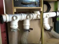
In the blast chamber there are three blast gates, the blast chamber is 600mm long from the left black blast gates to the right steel blast gate and there is one 50mm blast gate connected via the 50mm pipe work which is 300mm above the 100mm hard pipe work , plus one 50mm Hoover point .
I also designed it for a minimum lift for all wood debris & dust hence why I didn’t want to go overhead unless I really had to , then only if it was to be lifting dust , so decided to drop as much pipe work to within(600mm) from the floor level . (Minimum lift).
After I got to this stage I could not find a blast gate to fit the 50mm pipe work So I made the blast gates which are a good starting point for this thread.
50MM PVC BLAST GATES
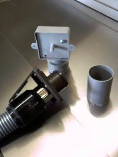
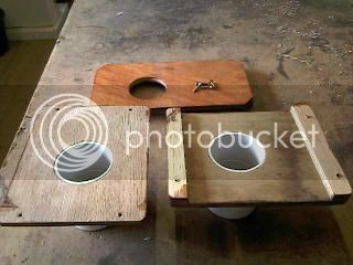
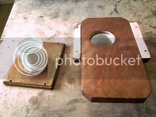
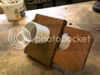
All the 50mm blast gate were made from PVC piping which all came from a company who sells a product called FloPlast here in Weymouth www.floplast.co.uk/ on the trading estate which I’m sure many of you can obtain if you so wish . The blast gates are made from two straight couplings, two short length of pipe, and some off cut of 3/8” plywood left over from when I constructed my workshop, the short lengths of pipe are first glued into one end of both couplings and then the coupling glue into the suction hole in the ply wood which are shown as follows
Above showing short length of pipe work before gluing
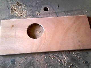
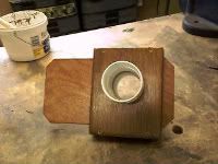
Showing suction hole
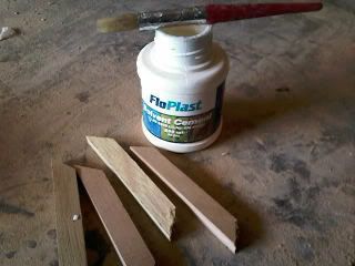
Showing glue bottle and hand grips to be glued
The dark areas are wet glue before hand grips were glue
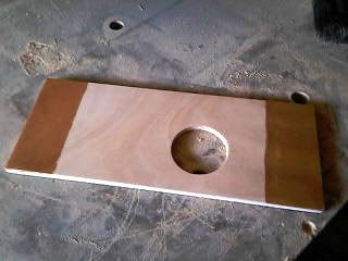
This last photo here shows a double hand grip glued , but that was changed , I didn’t like it so I cut off the outer two at either end, all other were then made with only one hand grip either end.
****************************************************************
This is the revised section that I missed out during the original post.
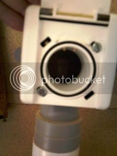
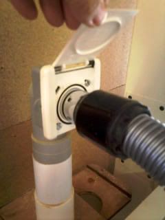
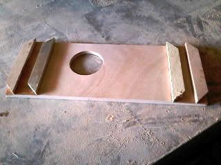
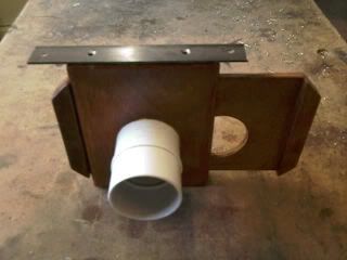
Shown here is how I assembled the blast gates .
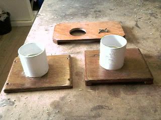
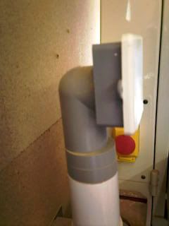
Metal strip shown on edge of a completed blast gate so it can be fixed to wall and secure pipe work in position .
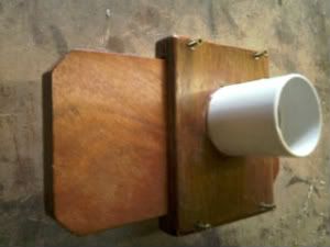
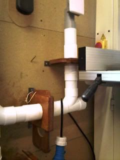
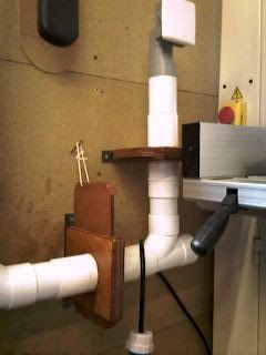
These two pics here show the blast gates in the vertical position closed and opened , just kept simple with a length of cord and a screw,
(just for you rob (woodbloke))
END OF THE REVISED SECTION
****************************************************************
These shots are showing the assemble blast gates from various views.

That just about covers how I went about making these blast gates.
The 100mm blast gates I decided to buy only because I could not find 100mm straight couplers at the time , and partly because of so many other thing going on in my life at that time , but in hindsight I wish I had researched for them a little longer. I used 100mm black plastic ones from Axminster tools, which also can be purchased from just about any good merchants , these get blocked with saw dust in the corners and then the gate won’t close properly so you lose suction, three has broken all replaced with metal blast gates.
50mm & 100mm ducting.
As mentioned, the main hard pipe machine ducting run is a total of 1.9m including the blast chamber of 600mm, so let’s start from the chamber and inlet pipe to the extraction inlet pipe which is 1.4 mm above floor level.
The three photos show the entire length of hard pipe ducting run (left) 1.1m. (Middle) is the blast chamber 600mm width 800mm height. (below) the entire lengths of hard pipe ducting run 1.9m including blast chamber.
flexible pipework.
From the blast gates these run to all machines independently in 100mm flexi .
Circular saw.
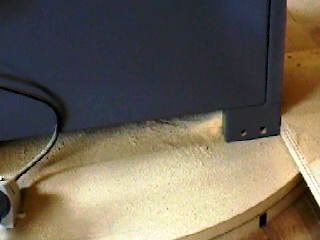
I have the saw mounted to on a turntable so no matter what position I lock the turntable in the flexi remains connected at all times along with the overhead saw guard.
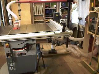
The first photo shows saw set at 90 degrees across the length of the workshop.
This photo shows the saw turned another 90degrees to the right still connected to the flexi pipe.
Planer
This again has a100mm pipe fitted permanently so I can easily change from overhead planing by simple opening the Planer beds and changing to thickness mode the flexi length is 2.5m
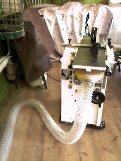
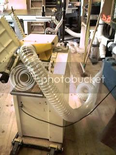
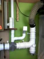
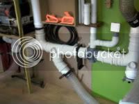
I have stated that I split the workshop down the length with all machine to one side of the shop, not quite correct with the one exception of the band saw 100mm and 50 mm Hoover point which I had to go overhead with both pipe runs, this pipes can be seen rising vertical in the centre of the right hand photo of the ducting hard pipe.
50MM DUCTING
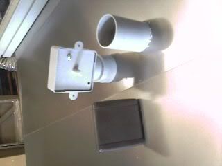
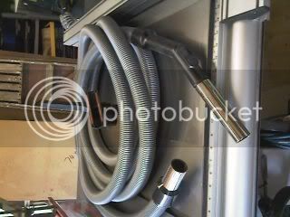
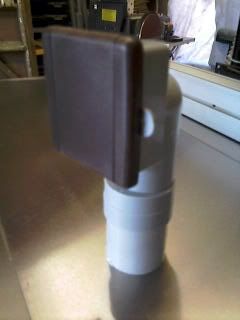
I fitted this for the extraction of dust from all power tools i.e.: router sanders and of course a Hoover system so I could get rid of all portable Hoovers and dust bucket plus leads and flexing pipes everywhere, I found this company www.cvcdirect.co.uk and bought three Hoover socket and a seven meter hose which when I plug into two of the sockets I can reach all corners of the shop from both sides of the shop for cleaning dust , the third socket still to be fitted which will be used outside the shop but plumbed through the wall into existing pipe work , so on those warm sunny day when I get to work out side to work I can Hoover all the decks and keep them clean as well .
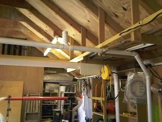
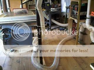
Showing pipe runs crossing the shop.
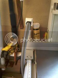
Showing Hoover point in lower section of photo where the third Hoover point will go out through the shed wall.
EXTRACTION UNIT DX5000 TWIN MOTORS
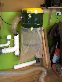
shown here with blast chamber, the steel blast gate will be connect to the lathe on the right via the pipes that can be seen in the photo.
Bits and bobs
Still to complete, the placement of a couple more Roding eyes in the 50mm system and the fitting of one more Hoover point.
Conclusion
The only down side of the hole system is the amount of dust that collects under the saw , I stress here not because of lack of suck but the bad SIP design around the saw blade , which is being discussed here at the moment on this very forum , wish they would hurry up and conclude all the design changes they keep coming up with , I’m following that thread with interest.
Well guys & girls hope you have enjoyed and it may be of help to someone out there, I know I enjoyed putting it all together, it’s taken a long time and a lot of money but well worth the effort it’s now finally has come together.
Hmm now what do I do now, ah yes complete my infill planes, my tool cabinet, and then ah yes, start my new bench. hc
This is my extraction system started last yr, now just about finished all but for crossing the t.s and dotting the I.s
I wanted to get the best from the system, I didn’t want to spend a heap of money and time fitting all this equipment and then not to be able get the best from it , I first spent a heap of time planning where machines and pipe work would go then slowly a plan came together, first I wanted as much suck as possible so decided to keep pipe runs to a minimum , but with each machine requiring a piped run to the blast chamber at first it was a nightmare I didn’t want all those pipe running over head like a spiders web going off at all different angle and all leading to one blast chamber that you see in so many workshops I decided on one hard pipe feeding all machine , which in turn had to feed the two system that I had decided on, it would also mean a long length of pipe connecting all machine possible running in all direction, this I didn’t like either.
The system incorporates two sizes of pipe work.
50mm 100mm for machinery.
50mm for light dust for hoovering & hand held power tools to cope with MDF dust, hence why I decided to design my own system in the first place.
This bought about my final plan to keep hard pipe work to a bare minimum I decide to split the workshop down the length with machinery on one side and working area on the other this gave me what I wanted the shortest possible hard pipe run of 1.9m including the blast chamber with an air/debris lift of 800mm to the inlet port on the extractor.
In the blast chamber there are three blast gates, the blast chamber is 600mm long from the left black blast gates to the right steel blast gate and there is one 50mm blast gate connected via the 50mm pipe work which is 300mm above the 100mm hard pipe work , plus one 50mm Hoover point .
I also designed it for a minimum lift for all wood debris & dust hence why I didn’t want to go overhead unless I really had to , then only if it was to be lifting dust , so decided to drop as much pipe work to within(600mm) from the floor level . (Minimum lift).
After I got to this stage I could not find a blast gate to fit the 50mm pipe work So I made the blast gates which are a good starting point for this thread.
50MM PVC BLAST GATES
All the 50mm blast gate were made from PVC piping which all came from a company who sells a product called FloPlast here in Weymouth www.floplast.co.uk/ on the trading estate which I’m sure many of you can obtain if you so wish . The blast gates are made from two straight couplings, two short length of pipe, and some off cut of 3/8” plywood left over from when I constructed my workshop, the short lengths of pipe are first glued into one end of both couplings and then the coupling glue into the suction hole in the ply wood which are shown as follows
Above showing short length of pipe work before gluing
Showing suction hole
Showing glue bottle and hand grips to be glued
The dark areas are wet glue before hand grips were glue
This last photo here shows a double hand grip glued , but that was changed , I didn’t like it so I cut off the outer two at either end, all other were then made with only one hand grip either end.
****************************************************************
This is the revised section that I missed out during the original post.
Shown here is how I assembled the blast gates .
Metal strip shown on edge of a completed blast gate so it can be fixed to wall and secure pipe work in position .
These two pics here show the blast gates in the vertical position closed and opened , just kept simple with a length of cord and a screw,
(just for you rob (woodbloke))
END OF THE REVISED SECTION
****************************************************************
These shots are showing the assemble blast gates from various views.
That just about covers how I went about making these blast gates.
The 100mm blast gates I decided to buy only because I could not find 100mm straight couplers at the time , and partly because of so many other thing going on in my life at that time , but in hindsight I wish I had researched for them a little longer. I used 100mm black plastic ones from Axminster tools, which also can be purchased from just about any good merchants , these get blocked with saw dust in the corners and then the gate won’t close properly so you lose suction, three has broken all replaced with metal blast gates.
50mm & 100mm ducting.
As mentioned, the main hard pipe machine ducting run is a total of 1.9m including the blast chamber of 600mm, so let’s start from the chamber and inlet pipe to the extraction inlet pipe which is 1.4 mm above floor level.
The three photos show the entire length of hard pipe ducting run (left) 1.1m. (Middle) is the blast chamber 600mm width 800mm height. (below) the entire lengths of hard pipe ducting run 1.9m including blast chamber.
flexible pipework.
From the blast gates these run to all machines independently in 100mm flexi .
Circular saw.
I have the saw mounted to on a turntable so no matter what position I lock the turntable in the flexi remains connected at all times along with the overhead saw guard.
The first photo shows saw set at 90 degrees across the length of the workshop.
This photo shows the saw turned another 90degrees to the right still connected to the flexi pipe.
Planer
This again has a100mm pipe fitted permanently so I can easily change from overhead planing by simple opening the Planer beds and changing to thickness mode the flexi length is 2.5m
I have stated that I split the workshop down the length with all machine to one side of the shop, not quite correct with the one exception of the band saw 100mm and 50 mm Hoover point which I had to go overhead with both pipe runs, this pipes can be seen rising vertical in the centre of the right hand photo of the ducting hard pipe.
50MM DUCTING
I fitted this for the extraction of dust from all power tools i.e.: router sanders and of course a Hoover system so I could get rid of all portable Hoovers and dust bucket plus leads and flexing pipes everywhere, I found this company www.cvcdirect.co.uk and bought three Hoover socket and a seven meter hose which when I plug into two of the sockets I can reach all corners of the shop from both sides of the shop for cleaning dust , the third socket still to be fitted which will be used outside the shop but plumbed through the wall into existing pipe work , so on those warm sunny day when I get to work out side to work I can Hoover all the decks and keep them clean as well .
Showing pipe runs crossing the shop.
Showing Hoover point in lower section of photo where the third Hoover point will go out through the shed wall.
EXTRACTION UNIT DX5000 TWIN MOTORS
shown here with blast chamber, the steel blast gate will be connect to the lathe on the right via the pipes that can be seen in the photo.
Bits and bobs
Still to complete, the placement of a couple more Roding eyes in the 50mm system and the fitting of one more Hoover point.
Conclusion
The only down side of the hole system is the amount of dust that collects under the saw , I stress here not because of lack of suck but the bad SIP design around the saw blade , which is being discussed here at the moment on this very forum , wish they would hurry up and conclude all the design changes they keep coming up with , I’m following that thread with interest.
Well guys & girls hope you have enjoyed and it may be of help to someone out there, I know I enjoyed putting it all together, it’s taken a long time and a lot of money but well worth the effort it’s now finally has come together.
Hmm now what do I do now, ah yes complete my infill planes, my tool cabinet, and then ah yes, start my new bench. hc