Miniature Traction Engine

UKworkshop.co.uk

Help Support UKworkshop.co.uk:

This site may earn a commission from merchant affiliate links, including eBay, Amazon, and others.
The black paint needs a mention. I needed a paint that could work at a high temperature for the chimney and the firebox.

I found this coal black paint, initially I thought this description was really describing the colour. However, this paint is designed for painting your fake coal on the gas fire....really.

coal-paint-07.jpg


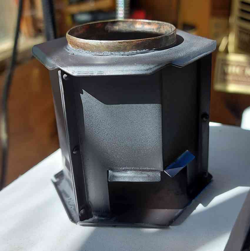
I had a quick search and saw that this paint is also used for stoves, so thought I would give it a go on the chimney and firebox. I've now fired the boiler a few times and this black finish is growing on me.

So, if you need a high temperature black paint then this paint from Rapide Products is rather good and cost me just £3.99 at a small hardware store.
 
After making the test boiler, fitting a DRO, adding a stiffening plate and sandbag damping to the milling machine....I'm back working on the Burrell traction engine. Today I roughed out a steering wheel whilst waiting for cylinder material.

steering-wheel-03.jpg

Not quite perfect, but considering it is 22mm across I'm ok, I might make another one....but for now.

I then parted it off and machined the other side. A little bit of filing, emery cloth and tumbling this afternoon.

steering-wheel.jpg


I need to add a handle so you can turn it fast
 
I built up the bottom end of the steering system. The phosphor bronze bearing has a recessed section that the brass tag was rolled into and a flattened side with step that aligns on the edge. This angled edge was machined at 38.5° to align with the steering column.

steering-bottomend-5.jpg

I think I'm getting more confident when working with sheet metal.

steering-bottomend-6.jpg

The worm sits snugly into the gear wheel. There is no chance that this can jump a tooth.

The bearing at the top end is a simple brass post. The steering wheel hub was machined from brass with an 8BA thread to accept the steering wheel. The steering column works very smoothly, just need to add the chains and attach them to the front axle.

steering-system-02.jpg


I had to reassemble the parts, I need to make the crankshaft as the flywheel is balanced on a much thinner rod at the moment, hence slightly too low.

steering-system-03.jpg
 
How can lumps of metal seem pretty. But (to me) it is.
Please post a video of it running when complete.
Thanks Dave, just lots of patience to sometimes make 3 or 4 parts before you get it right. Might be sometime before it's running, but will post progress. Best regards, Nigel
 
Not sure if everyone else is struggling in the heat in the workshop, it's definitely slowed me down.

However, I did managed to turn and mill the crosshead guide.

crosshead-guide-01.jpg


The inside surface of this is the bearing for the mid-point joint in the conrod. Thus allowing the sliding seal to work on cylinder and hence enable the double-acting operation of the cylinder.
 
The crankshaft has been made so that it splits into two parts. The conrod big-end then doesn't need to split. Thus I can reduce the thickness of the design as it doesn't need to have a bolt through it. Overall I can increase the crank throw and hence stroke.

I managed to squeeze the throw out to 7mm and still clear the firebox.

crankshaft-16.jpg


Thus the engine is 12mm bore and 14mm stroke double acting.
 
I made the valve chest from solid brass and then added the pushrod guides as one piece initially

valve-chest-03.jpg


Once this was silver soldered in place I then milled out the centre section, leaving me an aligned pair of bearings.

valve-chest-06.jpg


Now I have a roughed out valve chest, need to now make holes for fixings and the shaft gland nut.
That was cunning. I will try to remember that for the future alignment of bearing rods.
 
Back
Top