Miniature Traction Engine

UKworkshop.co.uk

Help Support UKworkshop.co.uk:

This site may earn a commission from merchant affiliate links, including eBay, Amazon, and others.
Hi Nigel, you will naturally understand that I also created a spread-sheet to determine my data :) - no where near as sophisticated as yours but sufficient to demonstrate that 'Prime' is more complex.

It's interesting to see that the lack of two even number hole-count plates makes even number divisions a problem. A 14 & 22 would solve it as well of course (or a 7 & 11)

If the D/Head were 40:1 rather than 90:1 then 28 would have 2 solutions (21 & 49 hole) & 44 just the one (33) but may not have as many other solutions - I haven't done the research o_O
 
you will naturally understand that I also created a spread-sheet to determine my data :)
Hi J-G, I thought exactly that. At some point I will probably make another plate, but as with most things I will probably leave that until I need it. Cheers, Nigel
 
Excellent concept Nigel. It's always easy to 'improve' upon an idea created by someone else - having the original idea is the difficult bit 👏

As you are aware, I am obsessed with precision, so the use of a 'bit of springy piano wire' did grab my attention. I can see that you need to alter the vertical position of the 'Detent' to select the 6, 8 or 10 hole level so piano wire for the arm seems perfectly valid. The [Detent] on the other hand might be better - in terms of accurate repeatability - if it were more substantial & tapered so that it fits more 'snuggly' into the Indexing Head holes.

You may already have taken this into account but you don't actually say so and the detent does not look to be anything more than another 'bit of springy piano wire' :)
 
As you are aware, I am obsessed with precision, so the use of a 'bit of springy piano wire' did grab my attention.
I think I lean towards the more 80:20 rule and get to a point where it is good enough for what I want and move on. However, that does cause me issues, as demonstrated by the traction engine where my design and make as I go along is starting to catch up with me. The tolerance stack at this scale is building and I'm going forward one step and backwards two.....
 
I think I lean towards the more 80:20 rule and get to a point where it is good enough for what I want and move on. However, that does cause me issues, as demonstrated by the traction engine where my design and make as I go along is starting to catch up with me. The tolerance stack at this scale is building and I'm going forward one step and backwards two.....

I've been following this thread for some time and I must say Nigel, that IN GENERAL, I agree with you in principle - "near enough is good enough" - a lot of the time anyway.

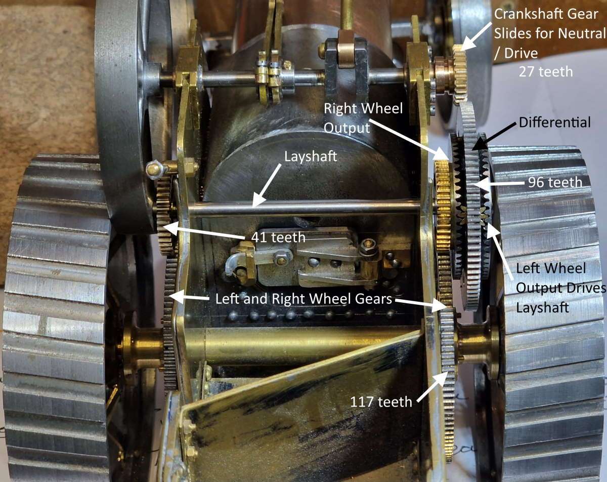
And your lovely looking traction engine project epitomises that approach. And normally, "we" don't see the problems unless and until you've pointed them out. (Hugely looking forward to seeing it in steam BTW).

But with a current project of my own (nothing "fancy" or "clever" like yours) where I've applied the same "near enough is .... " approach, this IS beginning to bite me in the posterior!

While I can understand and fully appreciate member JG's approach ("... to 4 places of decimals" - I'm now paraphrasing both you Nigel, and JG too of course), with my job in the final assembly/after painting stages I AM finding some places where parts that should move smoothly together are binding a bit, while on the other hand, some parts that should fit together snugly simply don't! Both of those lead to some reworking followed by, most probably, at least paint re-touching, if not full repainting!!!

Both lead to some frustration and extra time needed to finish (especially as I'm definitely NOT a lover of painting)!

So it seems to me that the best of both worlds would be to combine the 2 approaches - i.e. use ".... to 4 places of decimals......"; NOT where it's not necessary but where it definitely IS; while using "near enough ......" where I can get away with it.

The trouble is that like my project, IF it's the first and the last time I'll do a job like that, then I don't always know/understand whereabouts in the job the 2 approaches are the correct approach - UNTIL IT'S TOO LATE that is!

I guess it's called "experience" and to me anyway, that's one of the attractions of trying to make almost anything. (Well sometimes/mostly it is, anyway)! :mad::dunno::cool:

OK, no "value" here. Just "philosophising", FWIW
 
Last edited:
Finally the Burrell is back on the workbench and I've made the connecting rod from 3 parts

Here with the phosphor bronze big end in place. Hopefully the matchstick gives you an idea of scale.
conrod-03.jpg


conrod-04.jpg


The conrod was assembled from 3 parts
conrod-11.jpg


Finally with the conrod in place

conrod-13.jpg

let me know what you think or ideas
 
Finally the Burrell is back on the workbench and I've made the connecting rod from 3 parts

Here with the phosphor bronze big end in place. Hopefully the matchstick gives you an idea of scale.
View attachment 146886

View attachment 146884

The conrod was assembled from 3 parts
View attachment 146885

Finally with the conrod in place

View attachment 146887
let me know what you think or ideas
If I keep learning I should have caught up with your skill level in about 20,000 years 😀
 
If I keep learning I should have caught up with your skill level in about 20,000 years 😀
my dad bought me an Emco Unimat 3 when I was 11 years old and taught me how to machine, 45 years later and I'm still learning, still making mistakes

my machining is way behind the work I see from tool makers, but I enjoy my time in the workshop
 
Spent a few hours making the eccentric pushrods and then testing them on a drill:

eccentric-straps-08.jpg


The two eccentrics gives the ability to run the steam engine in forward and reverse. I need to make up the slider, crank and handle etc

They need a bit more fettling and finishing of the eccentric pushrods, but I'm happy for now.

 
The differential sits on the layshaft and this takes a bit of thinking about. Hopefully the following image helps. More details of the ratios here: Burrell Crankshaft and Layshaft Gears - glue-it.com

burrell-gears-01.jpg.jpg


The drive and neutral is achieved by sliding the crankshaft gear out of mesh.


Lots more to do, but gradually getting closer to completion.
 
Back
Top