Help required please - motor and swith - old drill press

UKworkshop.co.uk

Help Support UKworkshop.co.uk:

This site may earn a commission from merchant affiliate links, including eBay, Amazon, and others.

Starjump

Established Member
Joined
4 Mar 2017
Messages
116
Reaction score
21
Location
Hampshire
Hello, I am giving my old 'Atlas' drill press a new lease of life! New bearings, cleaning and prettying it up etc, all of which is well in hand, even discovered a 1942 date stamp! I imagine that it was originally exported to Britain during the second world war. I like American engineering of that vintage, the first half of the twentieth century, as it was solid in engineering terms and my grandfather spent the majority of his working life working for the Rambler / Hudson Essex / AMC organisation, I grew up with his reminiscences.

Sorry I digress. I would like to ask for advice please with regard to the electrics.

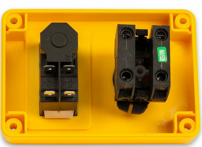
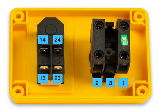
The lovely old motor bears the name: 'The British Houston Co. Ltd. Rugby, England A.C. Motor'. It works through a 'STARTET' push button switch, the motor is 1/3H.P.

The wiring was loose at the motor terminals, the wiring terminal cover and wiring gland are missing. The motor is dirty / oily, but it all functions ok, the dodgy noises were emanating from the drill!

I was planning on stripping the motor to give it a clean and replacing the cable and the switch. The old switch has done well but needed quite a firm push to operate.

Any suggestions as to which switch I might buy? Are there any resources specific to the to motor, that I might read before stripping it down? I had some friendly help with my drill enquiries on an American forum specific to this manufacturer. As we have 240v and our own electrical regulations, I imagine it is better to ask about the electrics this side of the Atlantic!

Thank you.
 
The motor identification plate.
 

Attachments

  • IMG_20200517_145152.jpg
    IMG_20200517_145152.jpg
    954 KB · Views: 110
'Atlas' drill press
 

Attachments

  • IMG_20200404_091920_resized_20200404_093957660.jpg
    IMG_20200404_091920_resized_20200404_093957660.jpg
    1.8 MB · Views: 108
A lot of equipment came across during the war on a "lend lease" basis. The Uk finally finished paying for it in the late 60's if I remember correctly :roll: :lol:

I think you need to wait for a better qualified person to come along, but that motor is rated a 250 volts. The Uk is down to 220 volts now so it will run slower than it was designed for.
I think an ordinary NVR switch will work, but wait for confirmation.
 
After WW2 I believe the UK had a debt of 21 billion, which we finally paid off on 31 December 2006, a lot more recently than most people think. Our final instalment was £45.5 million. No war reparations after WW2!
 
Thank you for your replies, world history is more tangible when it relates to people or things you have some contact with.
I bet we all have (tool) boxes full of stories.
 
sunnybob":5ixdnoxm said:
A lot of equipment came across during the war on a "lend lease" basis. The Uk finally finished paying for it in the late 60's if I remember correctly :roll: :lol:

I think you need to wait for a better qualified person to come along, but that motor is rated a 250 volts. The Uk is down to 220 volts now so it will run slower than it was designed for.
I think an ordinary NVR switch will work, but wait for confirmation.
I see 220/230V on the plate, which should be perfectly acceptable on the UK 240V supply. (Should be 230V to harmonise with EU, but we never bothered).

NVR switch will be fine. 1/3hp is about 250W, so only one amp. Get, say, a 5 or 6A rated switch to cope with start-up. Sometimes the switches are classed as DOL (direct-on-line). This means straightforward on/off.
 
My old eyeballs playing up, I thought that was 250.
In that case, it was never intended for England, because back then we had 240 and that would have ceased working quite quickly. 220 / 230 was europe, so it was most likely sent to germany to help rebuild (I expect the british military). Then it found its way back to the UK.

The UK had to step down its voltage to get into line with europe when we joined the EEC (long before the EU).
 
I know both of these NVR switches are 16A, but I like the form factor - having the mushroom stop button seems like a good design. Any thoughts?
 
sunnybob":1t4jf7tp said:
My old eyeballs playing up, I thought that was 250.
In that case, it was never intended for England, because back then we had 240 and that would have ceased working quite quickly. 220 / 230 was europe, so it was most likely sent to germany to help rebuild (I expect the british military). Then it found its way back to the UK.

The UK had to step down its voltage to get into line with europe when we joined the EEC (long before the EU).
Sorry - confusing EEC and EU! I’ll leave it there...

It will run fine on 220/230/240. After all, the UK acceptable mains voltage range is 216-253V. Insulation on these is typically tested to 500V; there’s plenty of leeway.
 
Starjump":3s70uvrn said:
Hi guineafowl22, thank you.

Would this type of switch be suitable please? - https://www.warco.co.uk/accessories/346-nvr-switch.html

Attached is the rear of the motor showing wiring.
That’s a big’un, but it will work.

If I were you I’d get some 1 or 1.5mm2 3-core flex and renew that old wiring all the way through. I always save appliance power cords for just this sort of thing.
 
Starjump":20hx91so said:
I know both of these NVR switches are 16A, but I like the form factor - having the mushroom stop button seems like a good design. Any thoughts?
Big mushroom stop to hit when the workpiece starts spinning... Good idea. (hammer)
 
Thanks Sunnybob, the motor was made in Rugby so I guess it was imported to Britain. I have seen on Google images Atlas drills with Canadian and American motors also, maybe the motor was affixed in the country of final destination, to meet local conditions? It would have been easy enough with 'v' belts and pulleys. As you say it should continue to run fine on the mains electricity. Good to know.
 
guineafowl21":25e9a4mq said:
Starjump":25e9a4mq said:
Hi guineafowl22, thank you.

Would this type of switch be suitable please? - https://www.warco.co.uk/accessories/346-nvr-switch.html

Attached is the rear of the motor showing wiring.
That’s a big’un, but it will work.

If I were you I’d get some 1 or 1.5mm2 3-core flex and renew that old wiring all the way through. I always save appliance power cords for just this sort of thing.

That is a good idea, I had planned on renewing the flex. Thanks.
 
Have found a picture of the rear of the switch. Have also seen reviews that mention no wiring diagrams accompany the unit.

Whilst an ohm meter would soon show which of the four terminals would serve the on-off functions of the push buttons at the left of the picture, could someone please explain how the emergency stop is wired in?
 

Attachments

  • Untitled.png
    Untitled.png
    445.3 KB · Views: 29
  • Untitled 1.png
    Untitled 1.png
    301.4 KB · Views: 29
Starjump":1t44y6sf said:
These are the numbers I can see from the picture.
It’s been a long time, but I think 13 and 23 are mains in, 14 and 24 out. You break the live through the mushroom switch on the way in.

The switch should come with a diagram printed on it anyway. Post it on here if unsure.
 
Back
Top