HELP - New NVR switch does NOT stay on :(

UKworkshop.co.uk

Help Support UKworkshop.co.uk:

This site may earn a commission from merchant affiliate links, including eBay, Amazon, and others.

tulogngham

StillJustAboutGotAllMyFingers
Joined
22 Feb 2011
Messages
43
Reaction score
4
Folks,

I need some advice. I brought a second hand table saw recently (iTech 315) and on bring it home and installing, I found the old switch was a bit temperamental.
Temperamental in terms of (1) If I bang the table, the motor switches on, 2) The green NVR switch sometime works, sometime doesn't work.
So I though that I would replace the switch but also add in an emergency stop bottom.
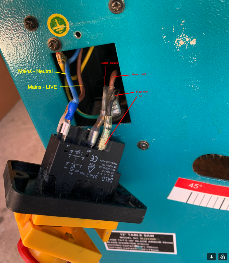
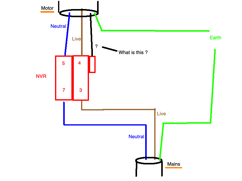
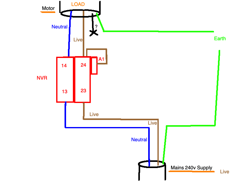
On opening up the old switch I found it pretty much EXACTLY the same as the new switch. So I've wired it as follows: See wiring diagrams.

Now on the new switch, when I press the button the saw turns on but if I release the button, the saw turns off !
Here are the wiring Ive done.

Q1. Could someone tell me what that small black wire is going to the motor ?
Q2. Is my wiring correct ? Sanity check please.
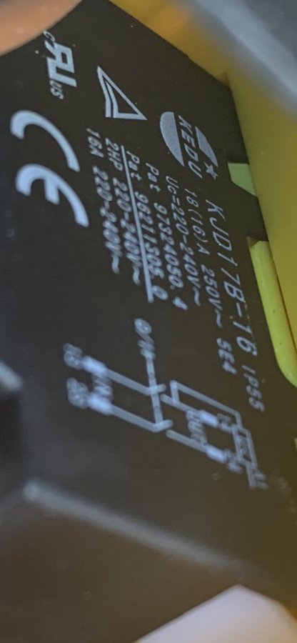
Q3. Have I got the right part in the first place ?

Tu
 

Attachments

  • Old NVR wiring diagram.png
    Old NVR wiring diagram.png
    25.8 KB · Views: 234
  • New NVR wiring diagram.png
    New NVR wiring diagram.png
    28.7 KB · Views: 272
  • New NVR wiring.png
    New NVR wiring.png
    860.6 KB · Views: 242
  • new_nvr_switch.jpg
    new_nvr_switch.jpg
    84.6 KB · Views: 214
  • new_nvr_switch_spec.jpg
    new_nvr_switch_spec.jpg
    42.6 KB · Views: 156
I can't tell you what the black wire from your motor is, but the reason your NVR is not working correctly is because you do not have it wired correctly to enable it to latch. The good news is this is easy to fix with most of what you have.

One side of the NVR latching coil is internal and the other side (Terminal A1) is intentionally not connected in case the user wants to use emergency stop switches, as you have. You will have two wires connected to Terminal 24 of the NVR so you will need to figure out how you are going to do this. I use Wago connectors to splice multiple wires as this is accepted here.

1. Unplug the mains cable from the receptacle before you start.
2. Remove the black wire from Terminal A1 on the NVR. Until you find out what this wire does, tape it up so it doesn't contact any component in the NVR housing.
3. Remove the brown wire from Terminal 23 of the NVR and connect it to Terminal A1 of the NVR. The other end of this wire remains connected to Terminal 1 of the Emergency Switch.
4. Remove the brown wire from Terminal 2 of the Emergency Switch and connect it to Terminal 23 of the NVR.
5. Connect a wire from Terminal 2 of the emergency switch to Terminal 24 of the NVR. This requires two wires on terminal 24.

This wires the emergency switch in series with the latching coil of the NVR.
 
Hi Mike,

Ive re-drawned your instructions in this diagram.
Q. Is this correct v2 ?

Tu
 

Attachments

  • New NVR wiring diagram v2.png
    New NVR wiring diagram v2.png
    34.1 KB · Views: 226
Hello Tu,

Yes, this looks good. It doesn't really matter if you reverse the connections on the Emergency Switch if you wanted to clean up the drawing.

The black wire from the motor could be connected to an internal thermal cutoff switch designed to protect the motor from overheating. If so, the other side of the switch is likely connected to the Line input at the motor windings inside the housing. This could be another safety feature you could easily incorporate, but you would need to verify it is a switched connection and not another winding to the motor. I'm sure @Myfordman could provide more information.

I ordered a 3-phase motor to convert my planer/thicknesser from single phase to 3-phase. The motor came without any documentation. The cable attached to the motor is a five-wire configuration with the standard 3-phase colors for each wire. When I asked the distributor about the motor configuration, he confirmed it was a 400V delta motor, and the blue wire that would normally be used as a neutral connection was the other end of a thermal overload switch buried somewhere in the windings. The other side of the switch was connected to the L1 input to the windings. I'll find out later when I test the motor on the bench.
 
Hi Mike,
Ive no experience with 3-phase, although I confess that I'm a graduate of Electronics Computer Science from Southampton Uni (1990) !
I've tried v2 today but unfortunately it has not worked. I have also removed the emergency cutoff out of the equation so have also tried v3 (enclosed) but again it has not worked.

I have also taken a closer picture of the wiring diagram. Enclosed.
Im still stumped on what feeds A1. Thoughts ?

Tu
 

Attachments

  • New NVR wiring diagram v3.png
    New NVR wiring diagram v3.png
    29.5 KB · Views: 97
  • Screenshot 2021-04-18 at 17.47.52.png
    Screenshot 2021-04-18 at 17.47.52.png
    1.1 MB · Views: 99
  • New NVR wiring diagram v2.png
    New NVR wiring diagram v2.png
    33.7 KB · Views: 92
Hi

I must say that these DIY NVR switches maybe cheap but I would not use in an industrial enviroment, a proper DOL starter is the way to go.

So Neutral to 13, Live to 23 when operated 14 is neutral and 24 live which you know is correct because it works whilst you hold the button in, so the hold in coil is not functioning. One end of this coil is internaly connected to 14 which is a neutral when the switch is operated, the other end A1 needs live to hold in and looking at your diagram this should work. With all the power OFF, and machine isolated check the hold in coil resistance between A1 and terminal 14, that should show a resistance and not be open circuit. It is looking like a faulty switch though.
 
Hi Tu,

The NVR is a manually operated relay (contactor) that is supposed to self-latch when A1 is connected to Terminal 24 of the NVR. When you push the green button on the front of the NVR, you force the contacts to close, which connects Terminal 13 to Terminal 14 (Neutral) and Terminal 23 to Terminal 24 (Line). Since the Line side of the mains connects to the A1 side of the coil, the coil remains energized when you release the green button.

What is not shown on the diagram are the internal connections for the red button, which is a normally closed switch in series with the coil. You don't need to worry about these since you can't access them.

A variation of the wiring is to use the emergency switch in series with the brown mains wire like you originally had, as long as the switch contacts are rated for the load. This will effectively remove all power from the NVR and prevent the motor from starting even if the green button is pushed. However, you still have to connect A1 to Terminal 24.

If the motor runs while you hold the green button in, but stops when you release it, then the latching coil inside the NVR is not working...assuming the wiring is correct. I've installed dozens of similar NVRs without any of the problems you are experiencing. Also, if the black wire from the motor is a Line connection through an internal thermal overload switch in the motor, then the diagram you have in the second drawing should work. I suspect the coil in the NVR is bad.

Edit: Roy beat me to it. :)
 
Last edited:
Mike & Roy. I’m coming to conclusion that it’s a duff switch. I will test it as mentioned. So I’m happy to go the DOL starter route. Do you guys have any recommendations? I have a Screwfix near me.
 
I’d like one with a emergency stop type button as it’s gonna be mounted on my table saw and if anything, it would be good nudge the stop with my knees.
 
My table saw is 4hp on 16A single phase. I will test that switch tomorrow and let you guys knows.
 
I am going with the new and old switches being different, or it isn’t wired correctly?
It is not acceptable to run the full load mains current through the e-stop button unless the switch OEM states that it is OK, and the switch terminals are rated at 16A AC-23. Never seen one at that rating yet.
If the e-stop is the same make as the “NVR Switch“, then it is 16A AC-1 rated.
AC-1 rating is for non-inductive, or slightly inductive loads. A motor does NOT fall into this category. So even, IF, the machine OEM has designed it this way, it is NOT compliant with the relevant product standards.
I am guessing that the black wire was on terminal A1, and is a return from a thermal switch in the motor windings.
I have done a rough sketch of how I would look to wire this.
Remember that I have not seen the machine, and I only have the sketchy information in this thread.
Take my advice at your peril, without a fuller knowledge of the machine I cannot be sure.
I have checked the “NVR Switch” OEM data, on the switch and their E-Stop in preparing this, however, I have no idea on the condition of the machine, nor the internal wiring of the motor.
A thermal switch, and e-stop however, are not designed to carry motor load currents, they are control devices.
NVR-Switch.PNG
 
Hi Paul,
Thank you for your diagram.
When I took off the previous NVR switch, I took a picture, and the black wire from the motor was indeed connected to A1. See pics enclosed..
 

Attachments

  • Old NVR wiring.png
    Old NVR wiring.png
    1,022.9 KB · Views: 60
Paul - Follow up question .. how do I know if the black wire is actually active ?
Tu
 
Please see PM reply.

I hadn't seen this post when I replied to the PM.

I would now wire this exactly as my drawing.
I believe that the black functions as I have drawn it.
 
Ref Paul's diagram if the themal cutout is open circuit there will be no live supply to the NVR and it won't latch, although the motor will run when the button is pressed. This fits the OPs description of the problem.
 
Folks,
...
Temperamental in terms of
(1) If I bang the table, the motor switches on
...
Tu
Ref Paul's diagram if the themal cutout is open circuit there will be no live supply to the NVR and it won't latch, although the motor will run when the button is pressed. This fits the OPs description of the problem.

A failed thermal switch doesn't explain the machine starting up when the table is banged though. This is why I don't believe the thermal switch is faulty.
 
Back
Top