Entry hall table for a niece

UKworkshop.co.uk

Help Support UKworkshop.co.uk:

This site may earn a commission from merchant affiliate links, including eBay, Amazon, and others.
Mike, this table is going to live in Sydney. Perth gets very hot in summer - 40+ C is quite common. However, it is very dry heat, and one just adapts to it. Sydney, on the other hand, gets very humid. Summer is the rainy season, unlike Perth, where we have a Mediterranean climate. So, wood moves a great deal in Sydney. This build has been all about taking care of movement.

With the legs, it is easy enough to guard against the unknown by adding 6 screws. :)

Regards from Perth

Derek
 
Mike, this table is going to live in Sydney. Perth gets very hot in summer - 40+ C is quite common. However, it is very dry heat, and one just adapts to it. Sydney, on the other hand, gets very humid. Summer is the rainy season, unlike Perth, where we have a Mediterranean climate.........

I know. I lived in Perth for 6 years as a kid, and I've lived in Sydney for 6 months.
 
This is the part where we begin building one-piece lipped drawers (as contrasted with applied fronts).

In preparing for this part of the build, my research uncovered exactly one article on dovetailing lipped drawer fronts. This is by Christian Becksvoort in Fine Woodworking magazine (#263-Sep/Oct 2017 Issue). Interesting that.

Why lipped drawer fronts? Simply because the three drawers must run continuously across the front, without a gap between them.

11a.jpg


The lipped sides will wrap around the drawer dividers, and these will double as drawer stops. This will be illustrated in a short while.

The lipped ends create a challenge to form the pins/sockets for the tailed drawer sides since it becomes difficult to saw. I have a novel solution :)

We begin by marking where the lipped sides will be. This is knifed in through from the rear of the case ...

Drawer2a.jpg


The marks are knifed with a cutting gauge.

The distance from the edge is exactly the same for each board - 6mm. The side spacers are 6mm wide and the two central drawer dividers are 12mm thick, of which each lip is half this thickness.

Drawer5a.jpg


The drawer front is rebated with a moving filletster plane ...

3a.jpg


With both sides rebated, the centre must fit snuggly between the drawer dividers ...

4a.jpg


... and leave exactly half of the dividers remaining ...

5a.jpg


6a.jpg


Side-by-side, perfect fit ...

7a.jpg


The rebates are fine-tuned with a cutting gauge, ensuring that they are even and square ...

1a.jpg


This measure is transferred to the drawer side ...

2a.jpg


I took the time to lay out the dovetails on a scrap as a template. This saves a lot of repeated layouts ...

3a.jpg


Tails done ...

4a.jpg


The tail board with be placed here, but with the lip extending past ...

5a.jpg


This is what it would look like if dovetailed ...

6a.jpg


To make it easier to see what I am sawing, I am using blue tape ...

7a.jpg


Transferring the tails to the pin board is made a little easier as the rebate is a handy stop ..

8a.jpg


9a.jpg


Marked out produces this ...

11a.jpg


And that is where it stops being straight forward as this is as much as it is possible to saw inside the lines ...

12a.jpg


I decided that, if I could not saw it, I would chop it. This gives new meaning to "chopping dovetails" :)

The pin board is clamped (to avoid any splitting), and the kerfing chisel is used to deepen the existing half-kerf, and then extend it across the socket ...

14a.jpg


15a.jpg


Now the waste is chopped out ...

16a.jpg


17a.jpg


This picture of a fishtail chisel cleaning the corner of the socket is for bill :)

18a.jpg


Does it fit? Oh, the suspense!

19a.jpg


20a.jpg


Two more to go.

Regards from Perth

Derek
 
Today I completed the second and third drawer fronts ...

7a.jpg


Since I had only come across one article on making the lipped drawers - and that predominantly used power tools - and failed to find a single video on the topic, I decided to make one myself:

https://www.youtube.com/watch?v=X0Ic08ERaf0

This is a real-time video - no editing. So skip the parts as they bore you. Hopefully some of it will amuse. Or watch at bedtime if you are insomniac :)

Regards from Perth

Derek
 
Thanks for that Derek. I just watched your video and found it very informative. That sort of real time watch-along seems to be quite rare on YouTube but it's actually really useful. Very clear commentary too.
 
Great video Derek, I enjoyed the views of your tools as well as your skills. Also the sound track - exotic Aussie birds?

One question re your vice (Morson?). It looks a bit flexible when you put your weight against it. Is this a drawback in practice?
 
The Moxon vise is not flexible. It is solid as a rock. However, I need to reposition the Gramercy hold downs behind it, as they are a bit too far away to centre on the Moxon's side pad, and hold it down firmly.

Regards from Perth

Derek
 
I stand corrected re the solidity of the vice. I can now see that the issue is with the position of the hold downs. Still, it’s not affected your ability to produce those superb joints.
 
The build is nearing the conclusion. The drawers, case back, and finish to do. Here, the drawers are continued. The focus of this article is on fitting the drawer (with lipped sides), and the fixtures that are used in the course of this process.

We ended the last build session with the drawer parts made ...

EntryHallTableForANiece11_html_5222b26b.jpg


... and the lipped drawer fronts completed ...

EntryHallTableForANiece12_html_1433a67d.jpg


First task today was to plane the groove for the drawer fronts ..

1a.jpg


The drawer sides and drawer back were dovetailed ... simple through dovetails. The notable feature here is that space is left for the drawer slip (which replaces the drawer groove as the drawer sides are 1/4" thick).

Of interest may be the bench hook I use. I suspect that some may look at this and wonder why I am butchering it by chopping on its top ..

7a.jpg


4a.jpg


Well, it is just scrap, and took about 5 minutes to make. So far this one has lasted about 3 months. I should get a few more out of it.

Not only is it used for chopping, but also sawing ...

6a.jpg


... and even shooting ...

5a.jpg


One of the issues with a lipped front is that it cannot be planed to fit after glue up. So, there are lots of dry fitting, and the sides are planed individually. This planing stop is invaluable for thin boards ...

8a.jpg


End-stop1.jpg


There is non-slip in the form of Crubber on the face of the stop ...

End-stop2.jpg


When fitted together, any raised pins need to be pared level. Here, the drawer is captured in a fixture (essentially, two pieces of ply, each with a cut out). The pins are pared with the newly-released Veritas flushing chisels ...

9a.jpg


I've had a pre-production set for a couple of years. This is what a prototype handle looks like ...

2.jpg


Veritas now supply this in a nice wooden handle. The one I am using is a design of my own, ala a Japanese slick ..

Chisels4_zpsvbyw2nls.jpg


Fitting the drawers also required positioning and glueing the drawer dividers. These also act as drawer stops ...

This is the drawer divider in position ...

10a.jpg


It is slid back ...

11a.jpg


The first third of the dado receives glue ...

12a.jpg


The drawer is replaced and positioned ..

13a.jpg


And then the drawer divider is slid up against the rear of the lip ..

14a.jpg


The drawer case is fine-tuned with the LN Rabbet Block Plane ...

15a.jpg


This is used to smooth over any irregularities in the side walls and, where necessary, to plane away any fat ...

16a.jpg


The drawers are in the process of being glued up. Drawer #3 cannot be glued up until a brass plate is recessed into one side. T

17a.jpg


Marked out, the waste routed, and then chiselled along the circumference ...

18a.jpg


19a.jpg


The drawer fronts are planed ...

20a.jpg


Another dry assembly and check for fit ...

22a.jpg


If there is any resistance to the drawer being pushed in-and-out, I test fit it from the rear. This shows whether the drawer or case needs some planing. Looking good here, as it goes right in ...

23a.jpg


There is good drawer extension (about 80%) ...

24a.jpg


The drawers are now glued up.

Lastly, for the day, the slips are attached. These began like this, grooved and beaded ...

20a.jpg


A Jarrah runner is added below. The upper section of the slip is, as with the drawer sides and drawer bottoms, made from Tasmanian Oak. This is similar to US White Oak in hardness and wear. Since the drawers run on Jarrah, the wear properties are improved with the Jarrah wear section ...

26a.jpg


Tomorrow should see the conclusion of the build.

Regards from Perth

Derek
 
I am going to have to block you Derek. Your skills make me feel inadequate. :D

Your niece is a lucky woman. Excellent work and very instructive thread and video. Thank you. I have learnt quite a lot. Invaluable.

AJ
 
This is the last part of the build - completing of the drawer bottoms and pulls.

A panel was prepared some weeks ago. 1/4" thick Tasmanian Oak. This was made up of two, book matched boards. Blue tape was used to pull the jointed edges together. Clamps are unnecessary for this task ...

EntryHallTableForANiece11_html_5222b26b.jpg


Measure off the full width of the drawer bottom from inside the slips ...

2a.jpg


Of possible interest is the work holding for the drawer bottom ...

3a.jpg


The bench dogs on each side were made from sections of unhardened O1 steel, and filed into teeth.

4a.jpg


Another heads-up is the arm for this cutting guard. Some while back, Veritas brought out a gauge with a fine adjuster. They now sell the arms to upgrade existing gauges, which is what I have done here to a wheel gauge I made ...

5a.jpg


Here the tongue is marked (about 4mm). This will fit into the groove in the slip.

The thickness of the tongue is marked (3mm).

6a.jpg


The tongue is planed ...

7a.jpg


The fit is tested with a spare slip ...

8a.jpg


The bottom was about 1mm too wide to fit. A LN edge was perfect to re-joint one side ...

9a.jpg


Re-establish the tongue with a shoulder plane ...

10a.jpg


Slide the bottom in. At this time it is just a dry fit. The front, which remains 1/4" thick to fit to 1/4" groove at the rear of the drawer front, is not yet pushed home. The front groove will hold the one end firmly, allowing movement towards the rear of the drawer.

11a.jpg


The drawers require pulls. The aim is to make the pulls "vanish" as much as possible. To do this, the shape is kept simple, and the wood is a section from the drawer fronts. Here it is being planed to 1/4" thickness.

12a.jpg


Set up to make the pulls ...

13a.jpg


A 10mm wide rebate is planed on both sides. This will be completed on the reverse side as well, to create a tenon 3mm thick.

14a.jpg


Four sections are marked off for the pulls (only three are needed) ..

15a.jpg


A router is used to create dimples for a finger grip on the underside of the pull (three were needed and were good here; one could be tossed) ...

16a.jpg


17a.jpg


The outlines are cut out ...

18a.jpg


The router is again used, this time to create a 3mm x 50mm mortice in the drawer fronts for the pulls ...

19a.jpg


The final section of the build is the drawer back. I decided to use Jarrah to match the rest - one never knows whether the hall table will become a room divider.

The newly-purchased JessEm Clear-Cut TS Stock Guides make a clean, accurate rip that much easier ...

20a.jpg


The next post will show the completed hall table.

Regards from Perth

Derek
 
Derek, was your heart in your mouth when you did that routing on the front of the drawers, given all the work you’d already put into them? One mm out and the thing would have been ruined. I wouldn’t have the balls.
 
Marineboy":1n1uq1rg said:
Derek, was your heart in your mouth when you did that routing on the front of the drawers, given all the work you’d already put into them? One mm out and the thing would have been ruined. I wouldn’t have the balls.

Nah ... not a problem. I was using a fixture I build for morticing with a router.

1a.jpg


2a.jpg


The router fence is captured in the groove at the rear.

4a.jpg


Clamp the work piece (drawer face), line up the router/bit, set the depth, and Bob's your uncle.

Regards from Perth

Derek
 
My niece is getting married at the end of March, the entry hall table she asked for is completed, and in a couple of days it will head off to Sydney.

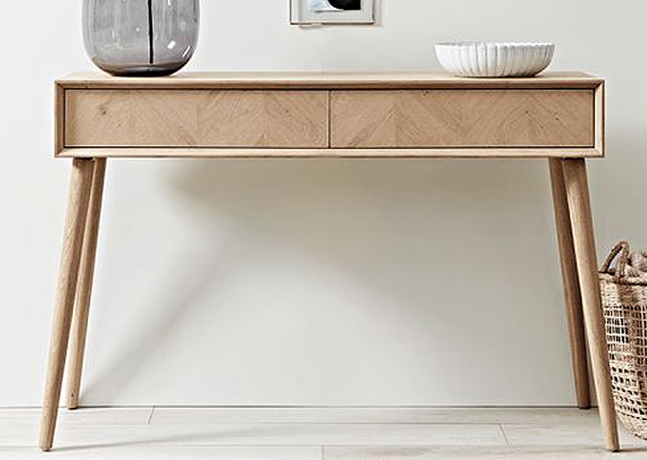
This is the model for the table she wanted me to build, but to build it in Jarrah ...

Jes-Entry-Table.jpg


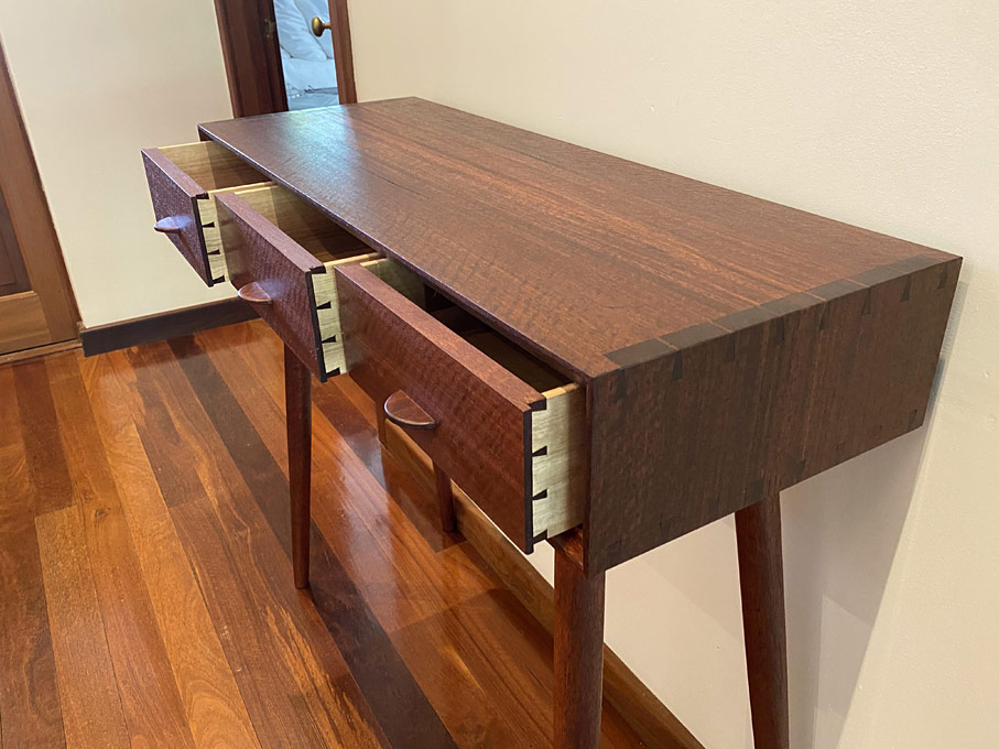
I needed to make a few modifications. The most notable were, firstly, that there are three drawers, where the model has two. With a little research, it became evident that the model was a "flat pack" build from a store in the UK, and it used slides and poppers for the drawers. Without slides, wide drawers will rack since the depth-to-width ratio is all wrong. Three drawers change this ratio and make it workable.

Secondly, building a drawer to ride wood-on-wood, one cannot use poppers - and so drawer handles are necessary. My niece was keen that drawer handles would not be seen, and I have done my best to make them unobtrusive.

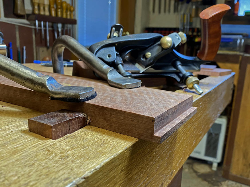
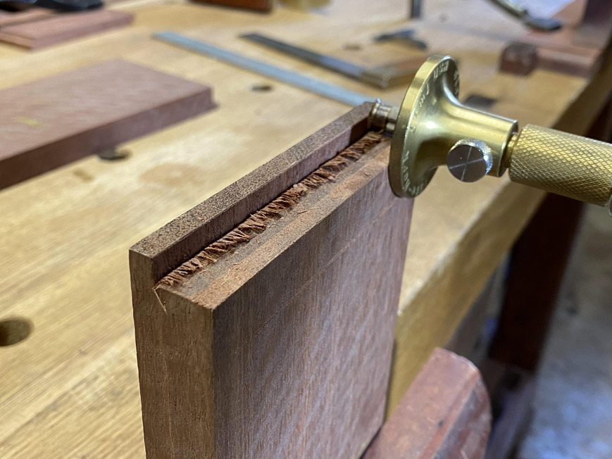
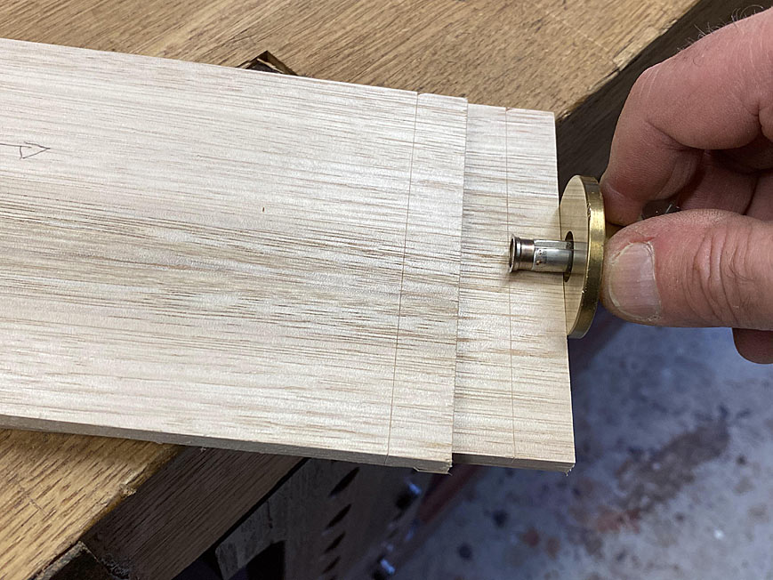
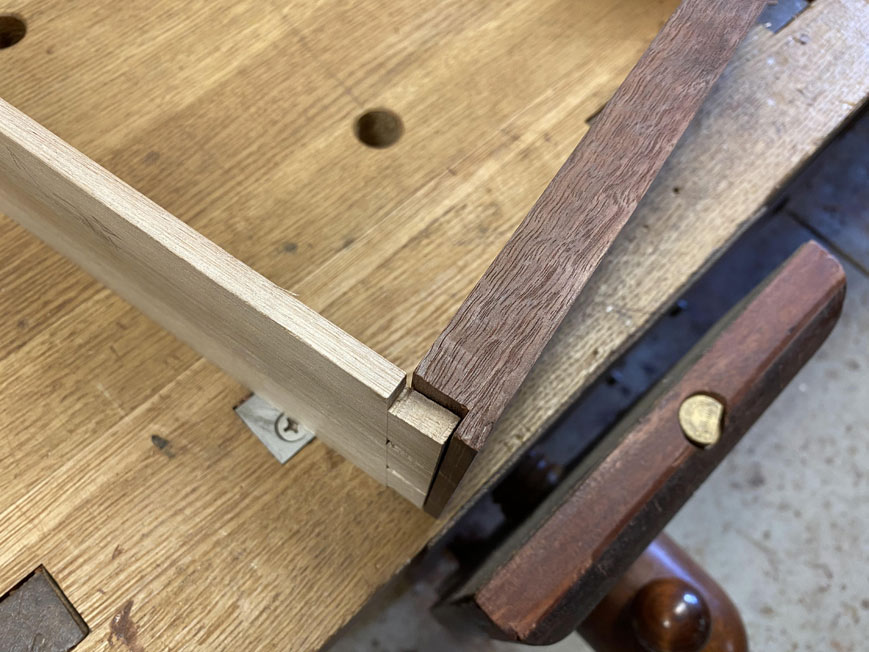
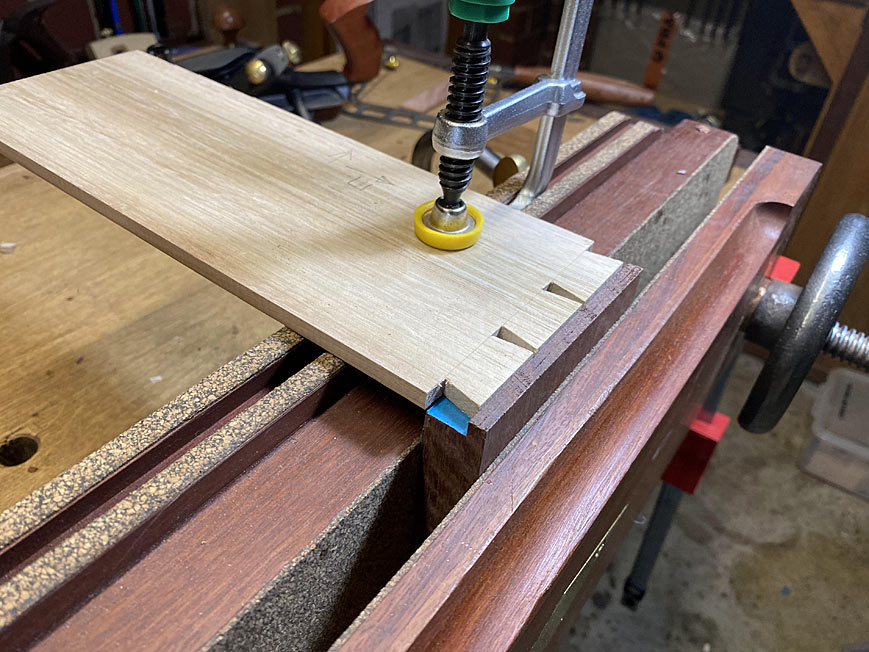
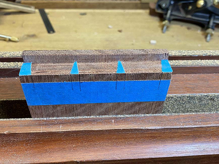
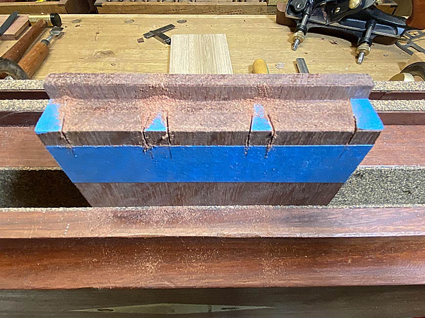
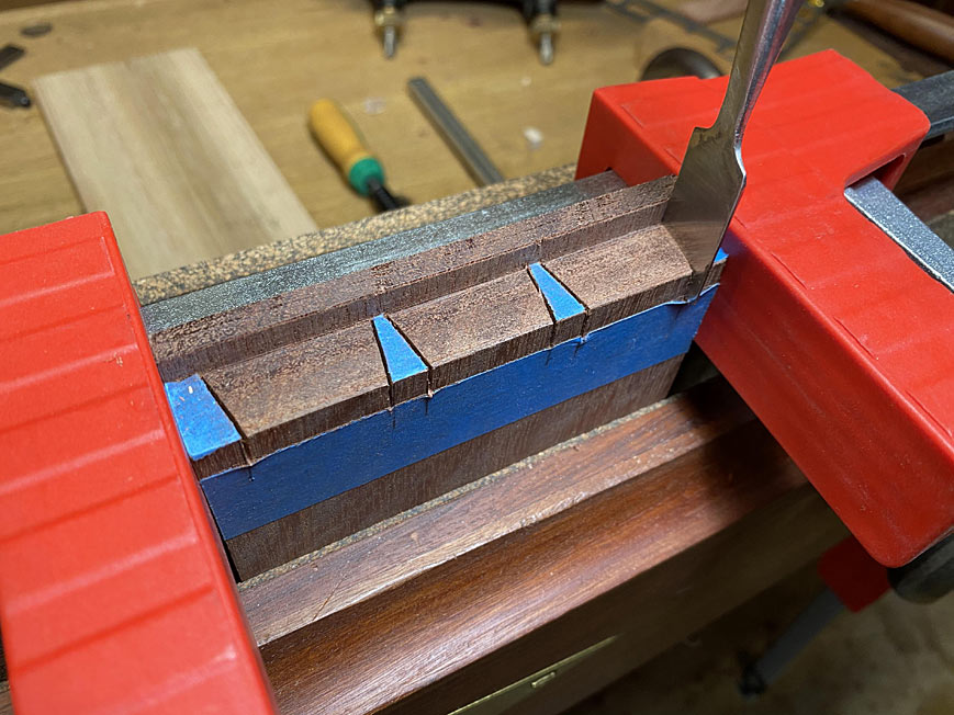
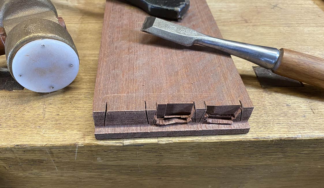
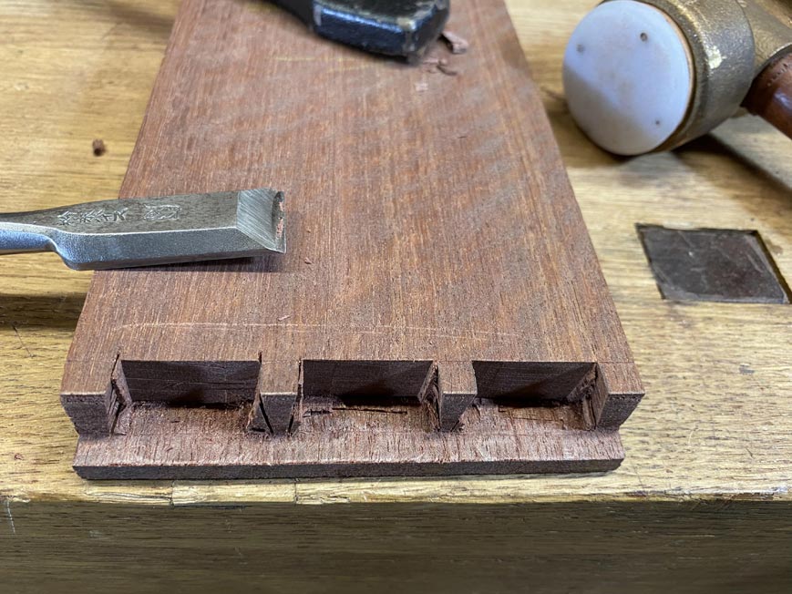
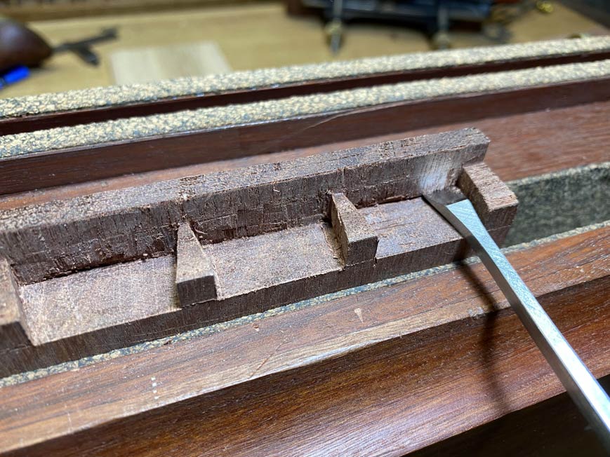
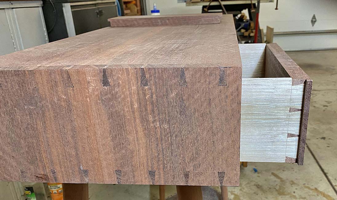
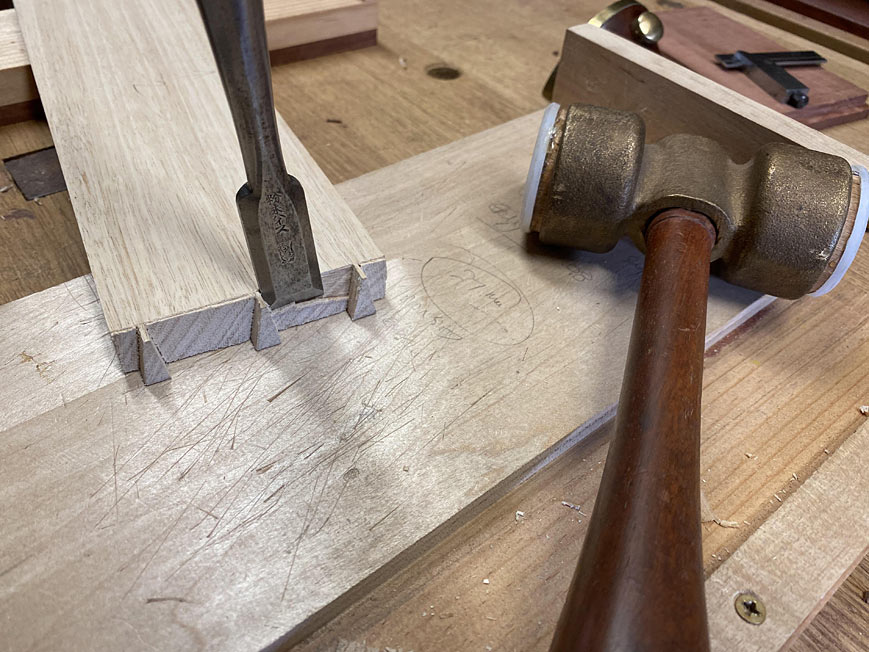
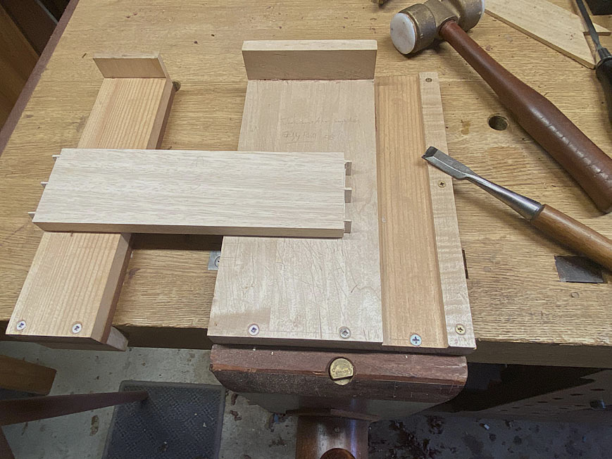
Together with the desire to avoid drawer handles, there was also the request to make the drawers appear to be a single piece, rather than drawers separated by drawer dividers. The fact is, we had to have drawer dividers. So, to hide them, drawer fronts were given lips, with a lip covering half the width of a divider. In this way, the dividers could double as drawer stops. Making lipped, half-blind dovetails was a first for me. In the end, they were not too bad.

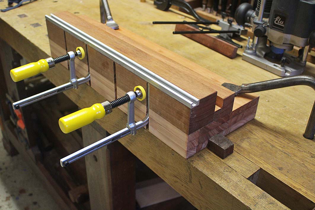
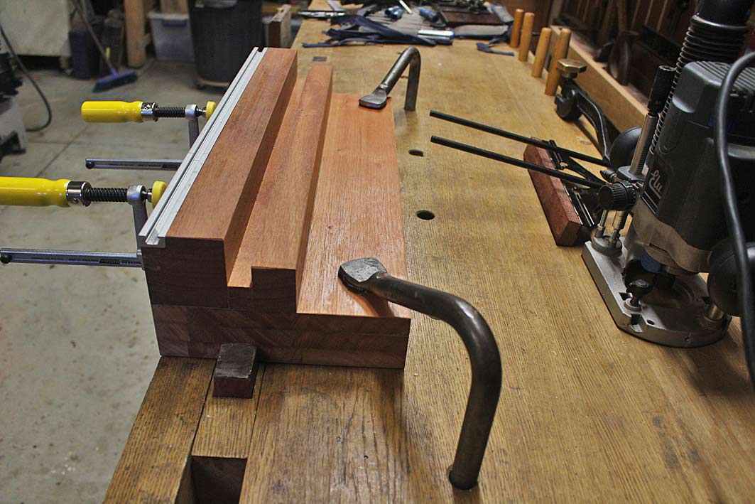
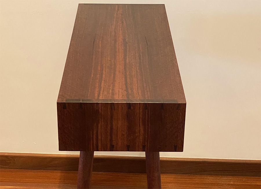
The case of the original table is mitred, and this is likely butt jointed and supported with either dowels, biscuits or dominos. My choice was to use mitred through dovetails, both for their strength and also for aesthetics. Although I have done a number of similar cases in recent years, this joint is one where you hold your breath until it all comes together. Then you wonder what the fuss was about :)

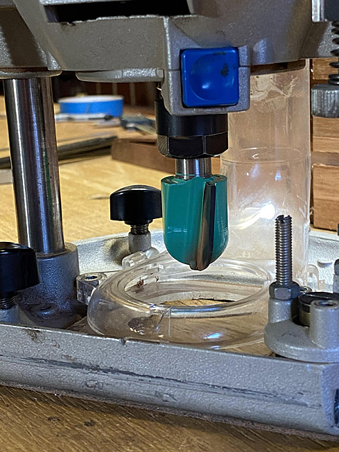
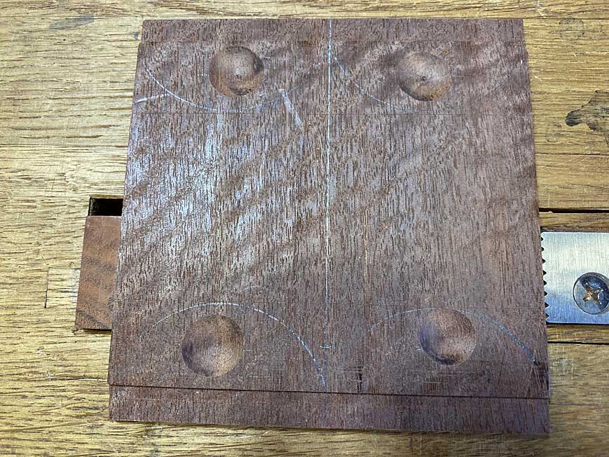
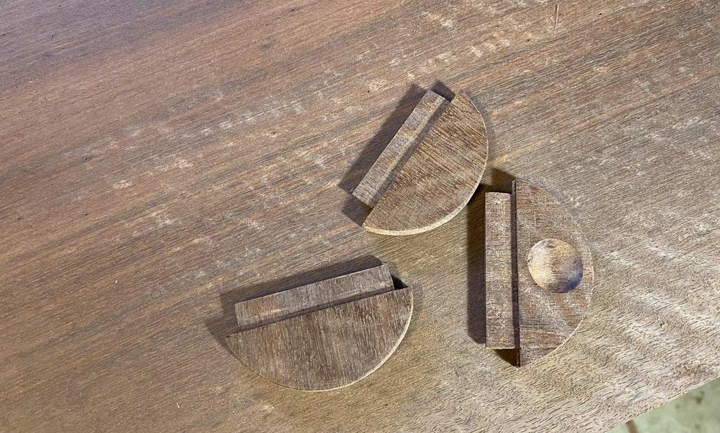
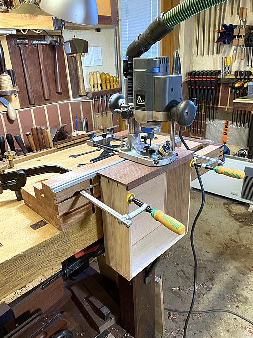
A fifth change was the attachment of the legs. The model likely used a metal screw per leg, which was common with Mid Century furniture. I wanted something stronger and durable so, in place of this, my decision was to stake the legs into a thicker base, which was firmly attached to the underside of the case with tapered, stopped sliding dovetails. A bit more work, but I will sleep better at night.

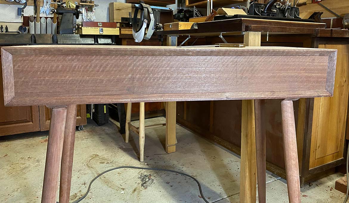
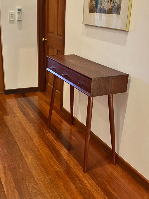
At the end of the day, it resembles a box, and only a woodworker will recognise that it is a very complex box. :)

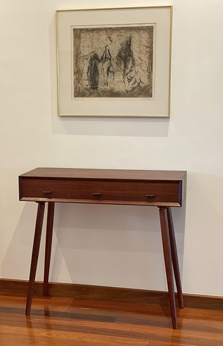
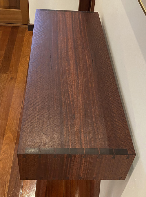
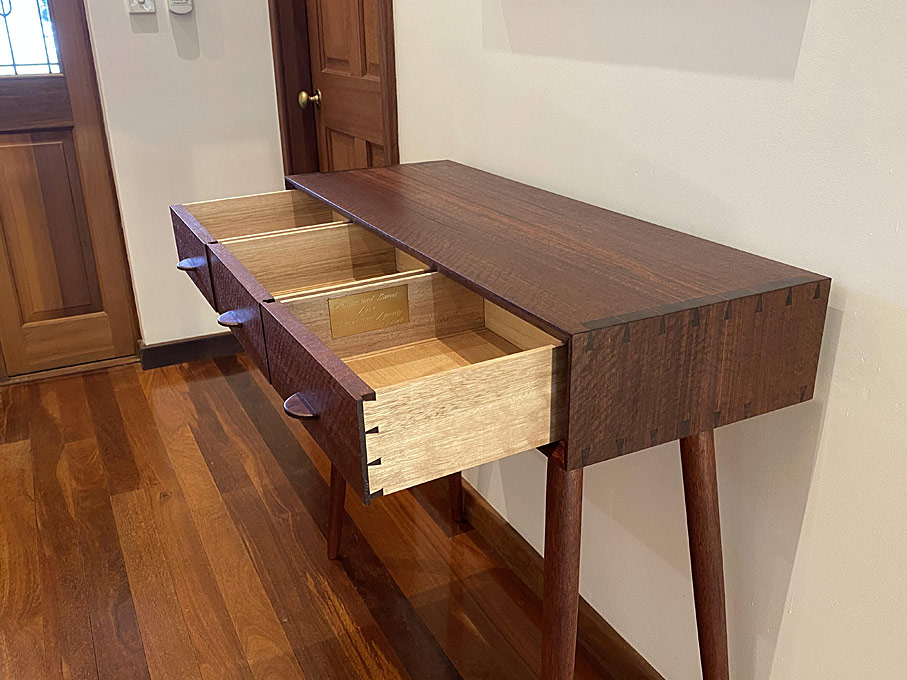
Okay, here it is. It is photographed in my entrance hall ....

1a.jpg


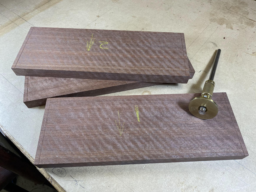
The wood is fiddleback (curly) Jarrah.

2-1a.jpg


3a.jpg


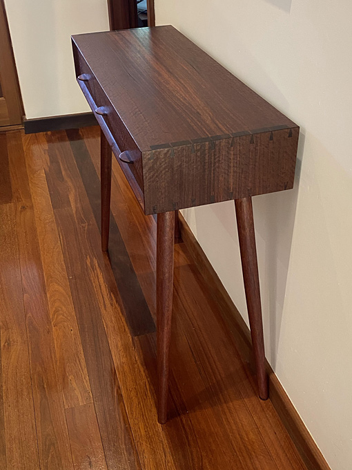
A close up the waterfall on one side ...

4a.jpg


... and on the other ...

5a.jpg


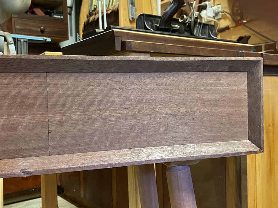
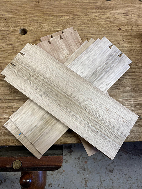
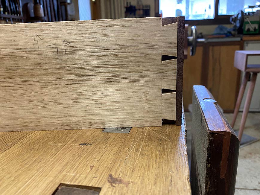
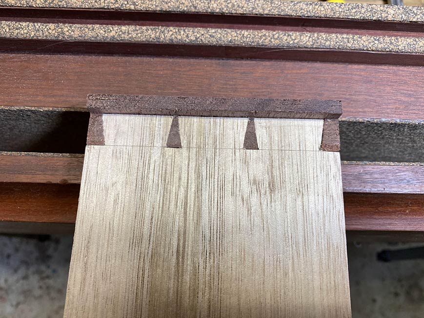
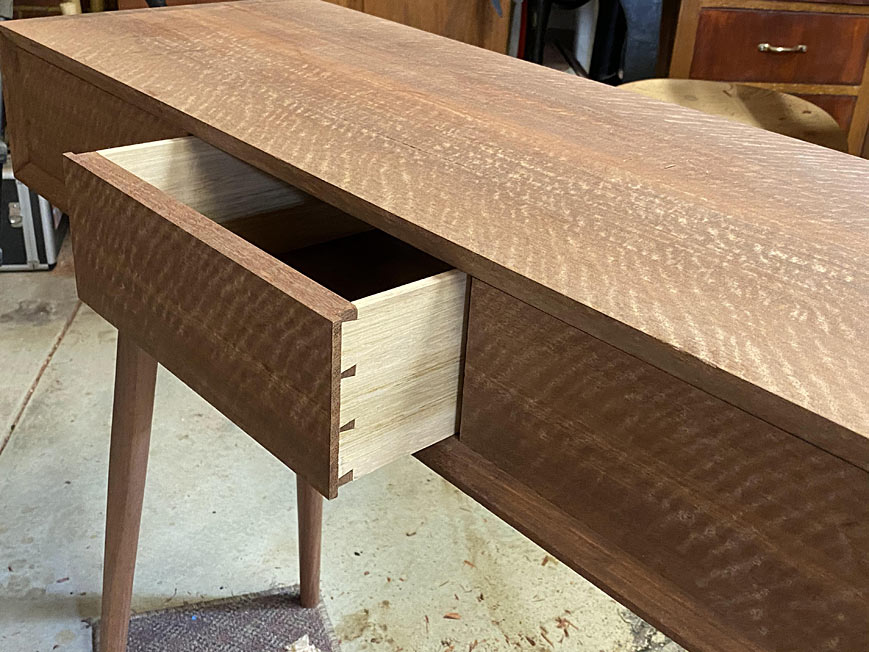
The obligatory dovetail shot ...

6a.jpg


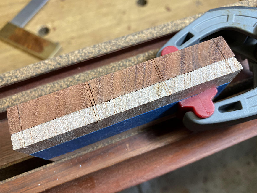
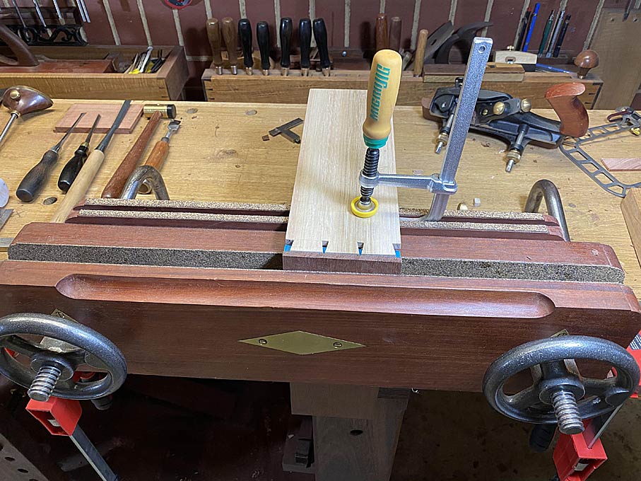
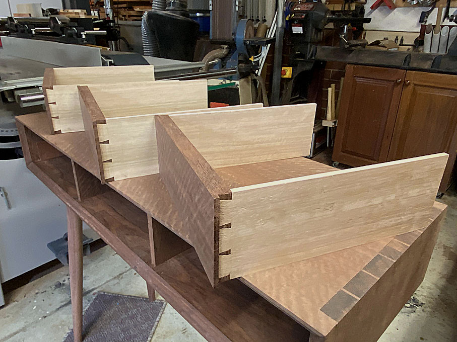
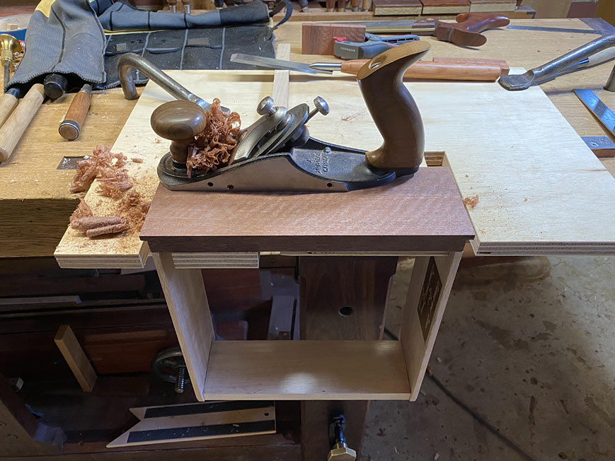
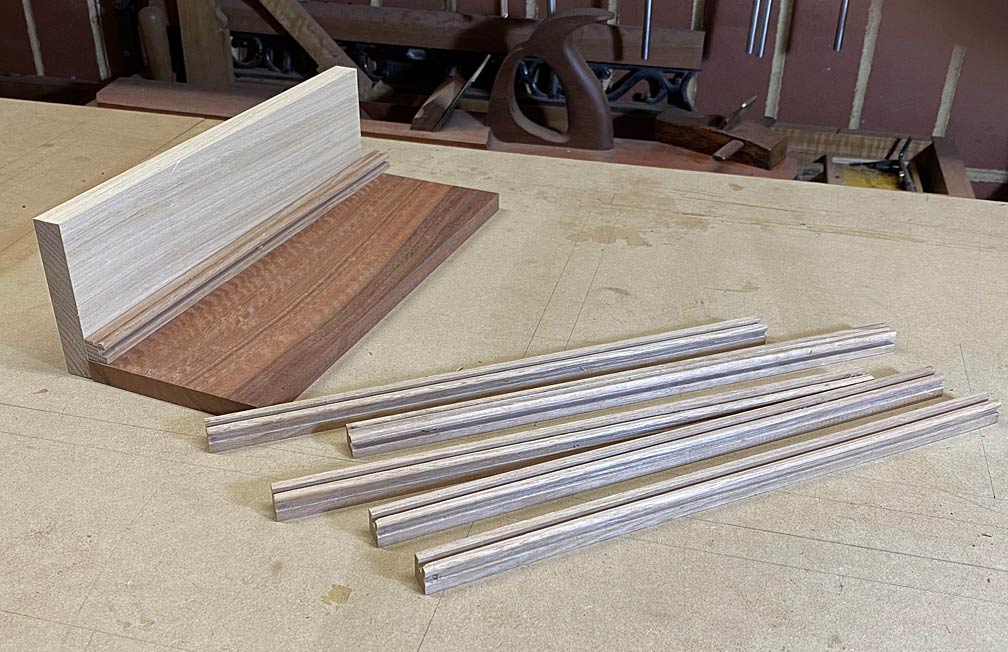
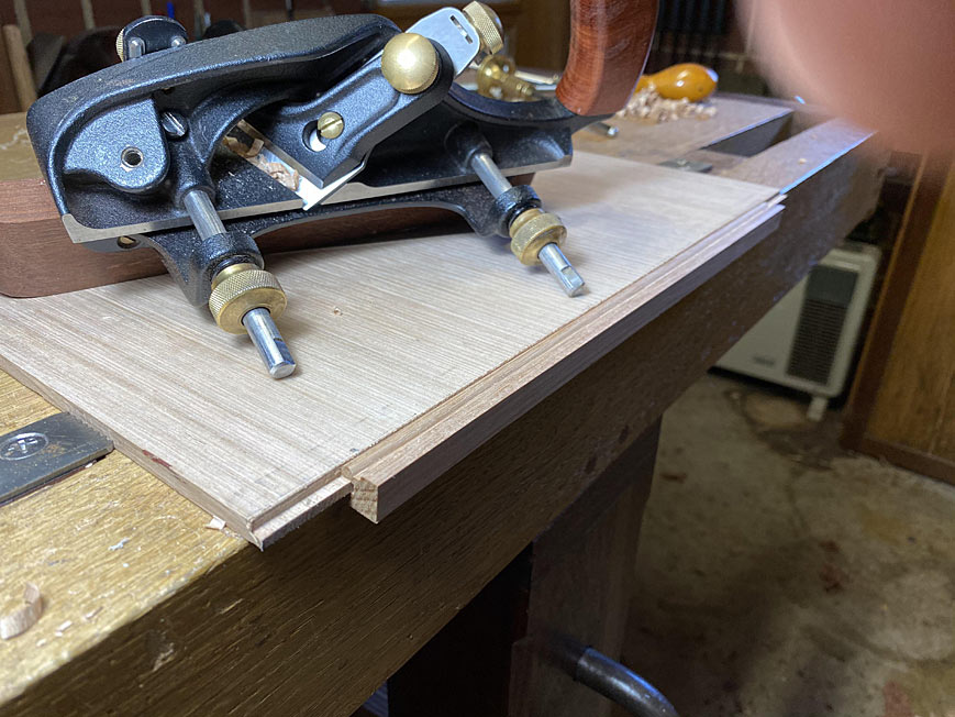
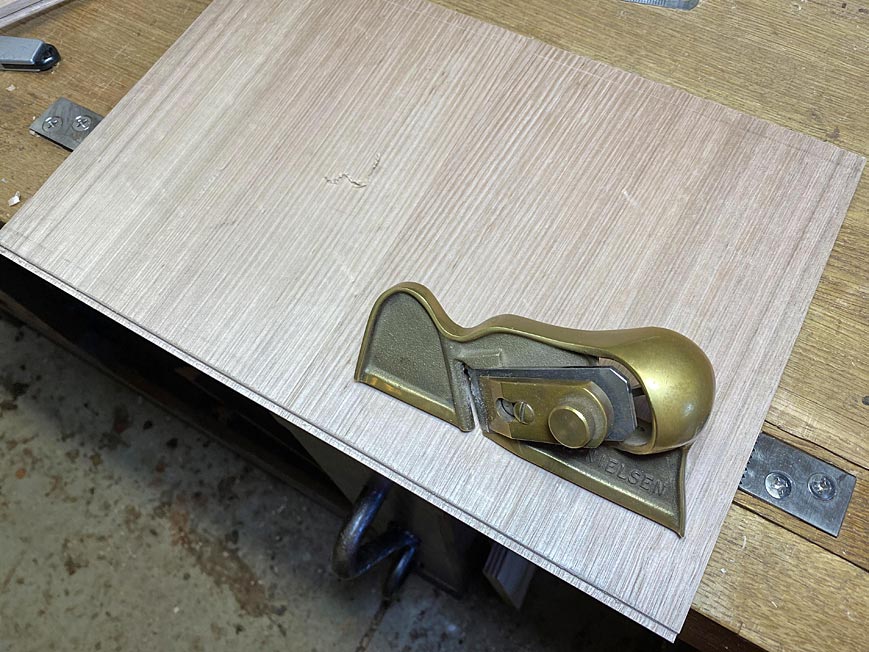
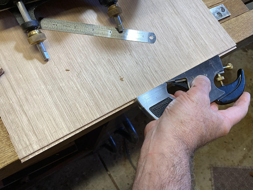
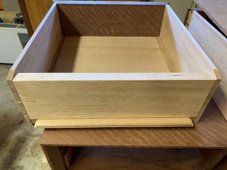
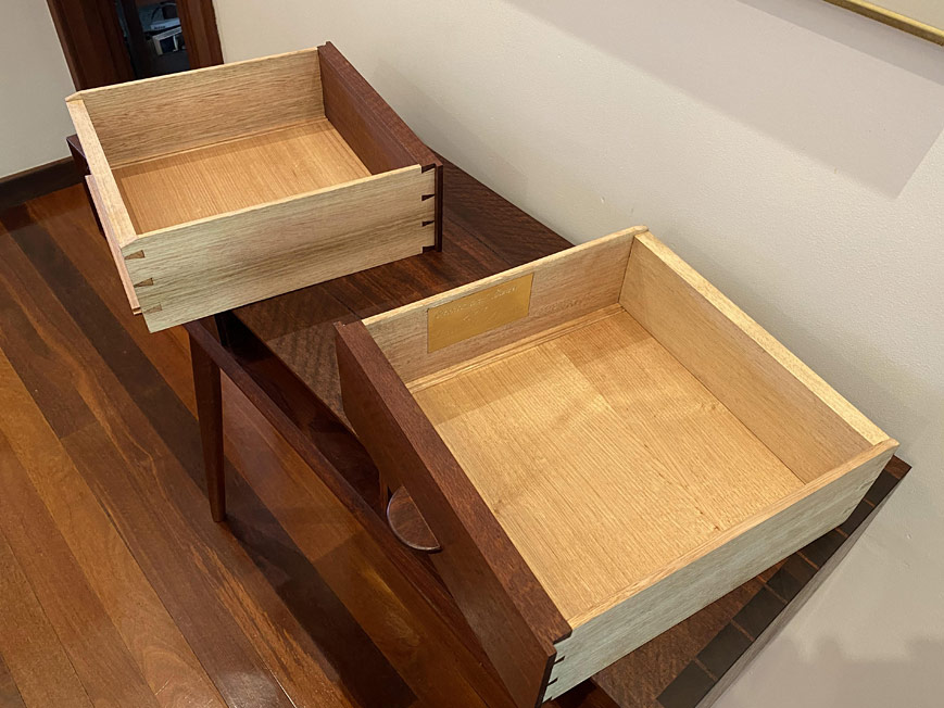
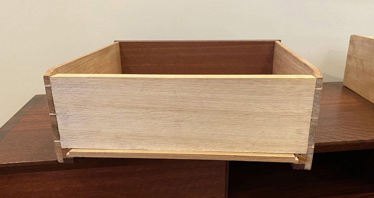
Those drawers! The lipped drawer fronts are 20mm, with the drawer sides 1/4". The back is 15mm thick. The thin sides necessitated drawer slips. These were beaded to create a transition from slip to drawer bottom. The drawer bottoms are 1/4". The wood used here is Tasmanian Oak.

7a.jpg


8a.jpg


9a.jpg


10a.jpg


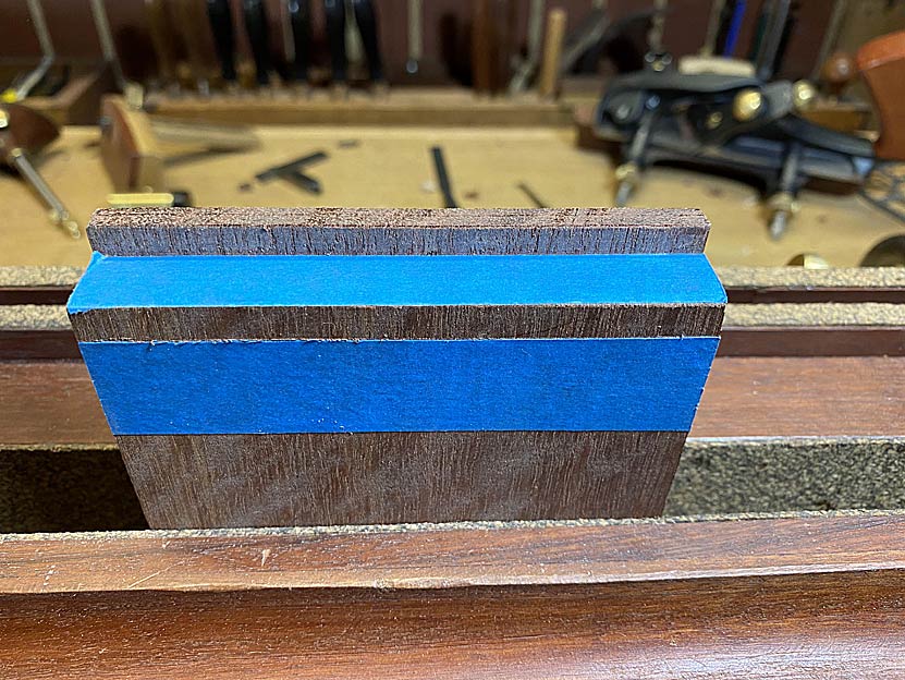
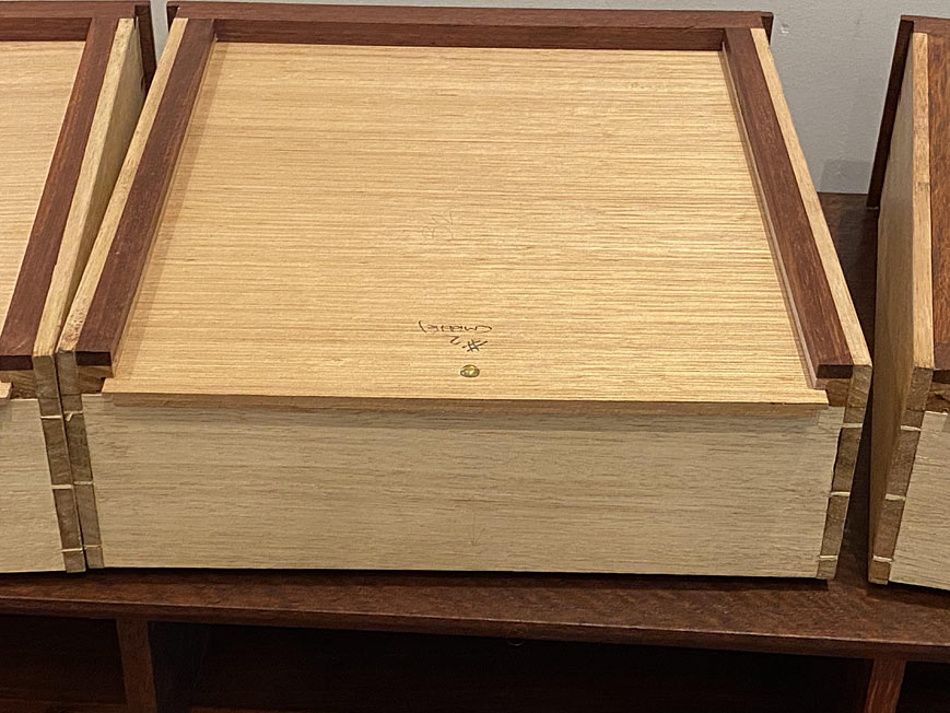
Since the case and internals are build from hard Jarrah, the underside of the slips was given a Jarrah slide to improve ware properties.

12a.jpg


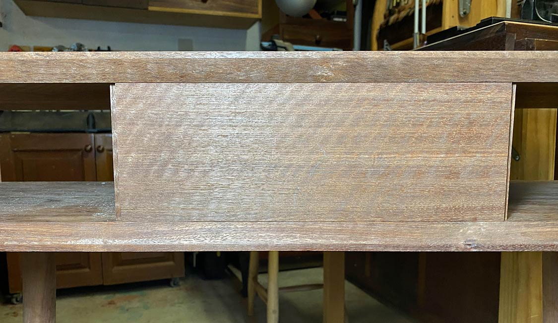
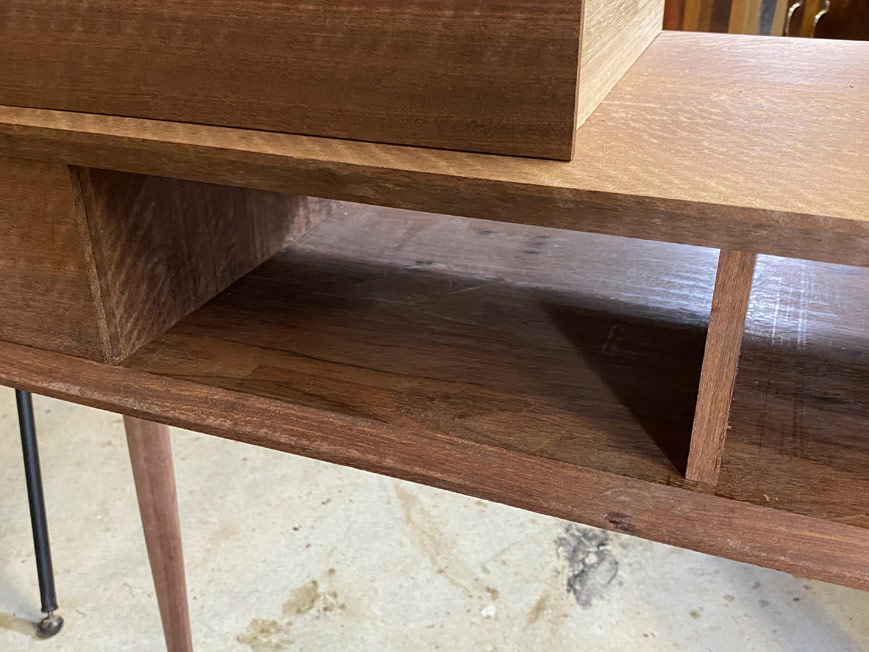
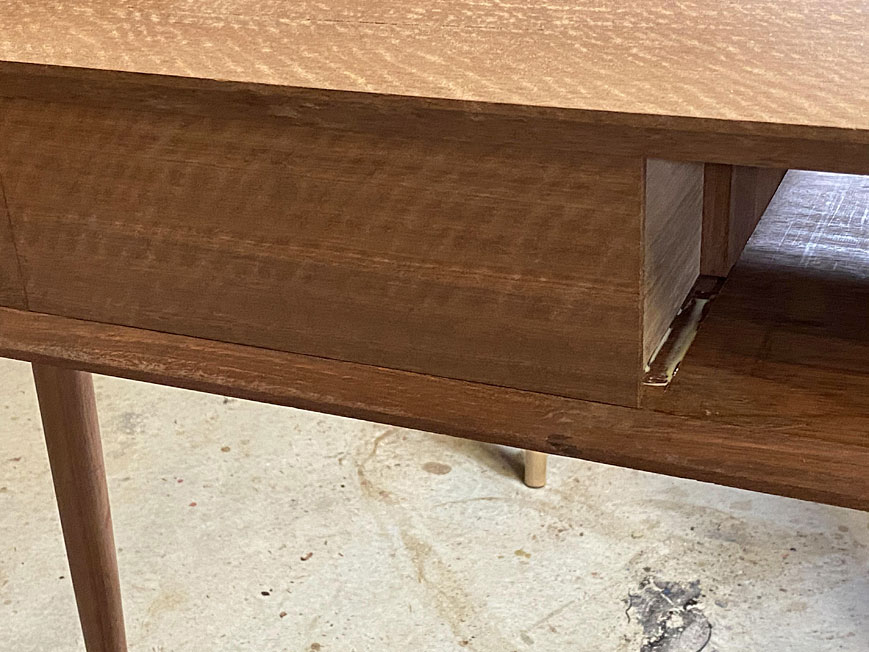
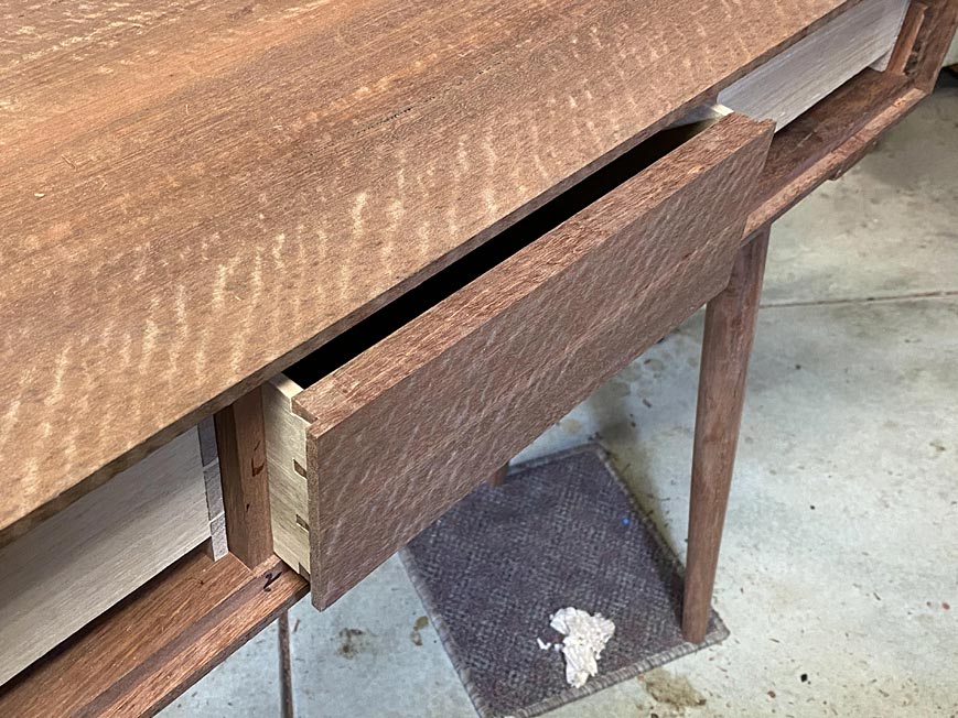
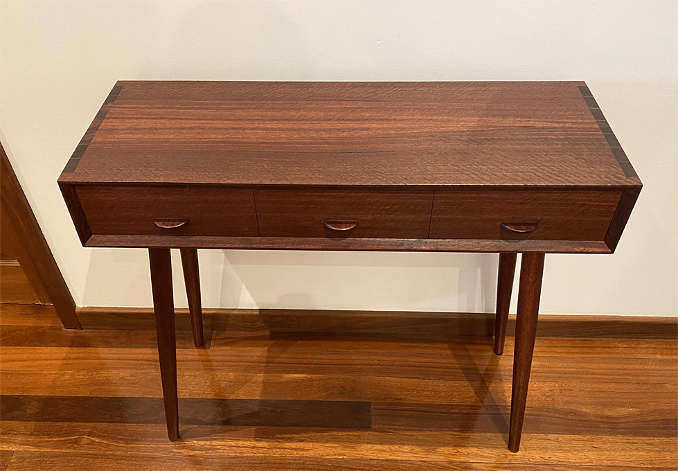
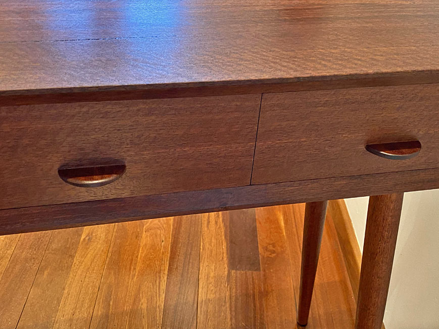
As mentioned earlier, the aim was to present a single board at the front ...

15a.jpg


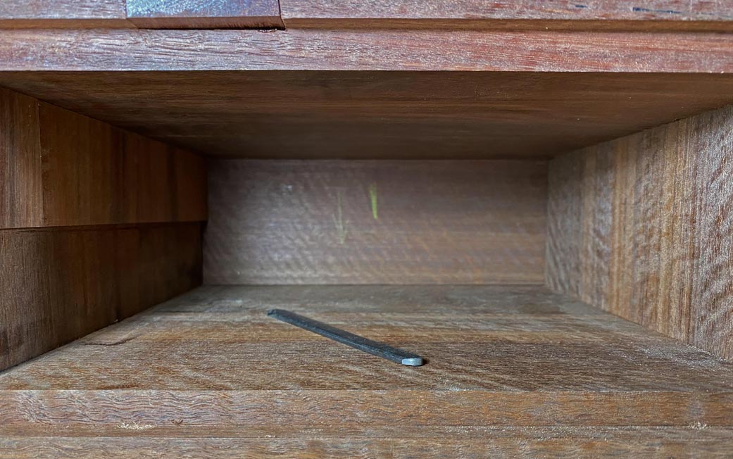
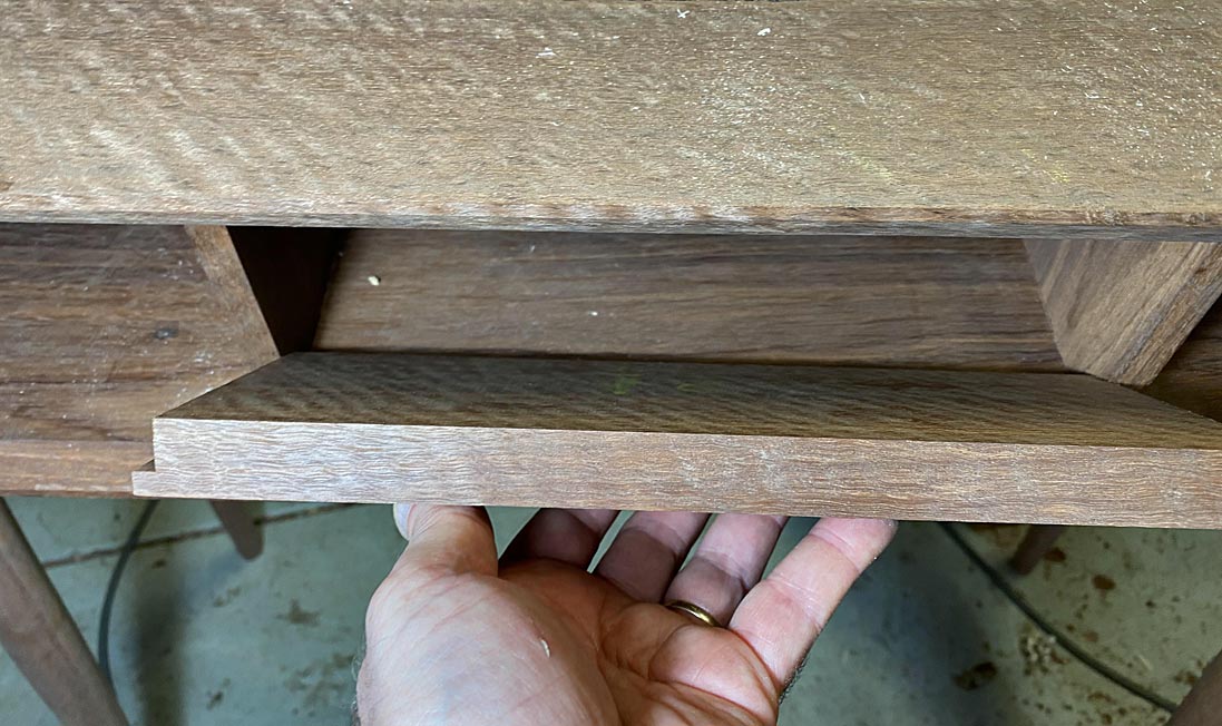
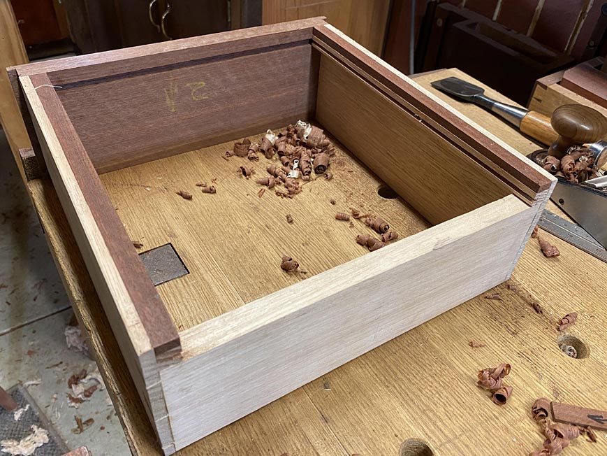
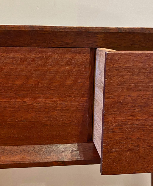
Here may be seen how the lips share the drawer divider and use it as a drawer stop. The spacers at the side of the case are half the width of the dividers as they do not share two drawers.

17a.jpg


18a.jpg


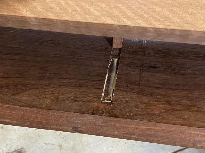
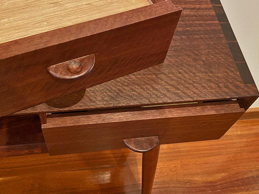
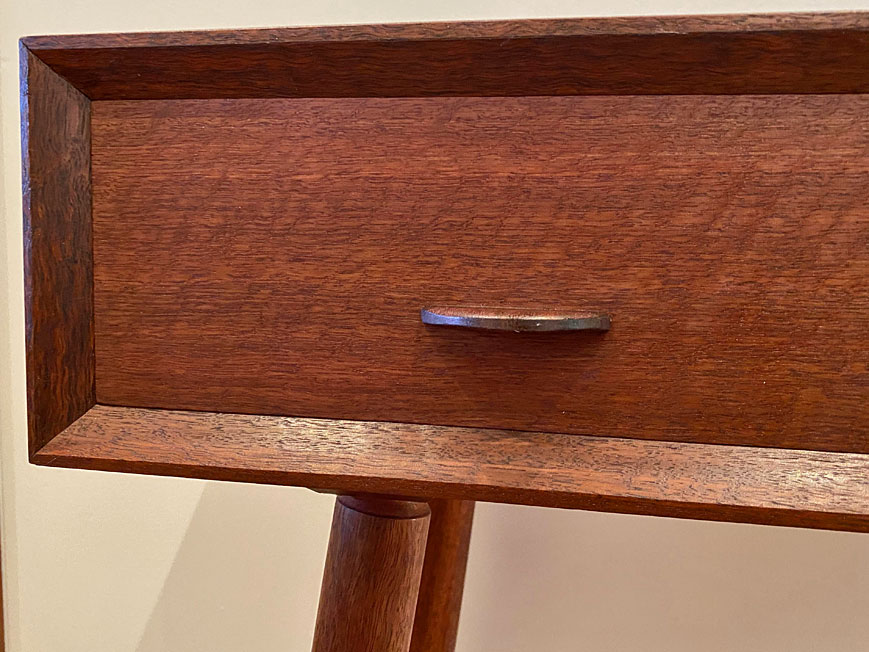
Now those drawer handles ...

I tried to keep the design as simple as possible, and used the same wood as the drawer fronts so they would blend in. The upper drawer shows the finger grip on underside of the handle ...

19a.jpg


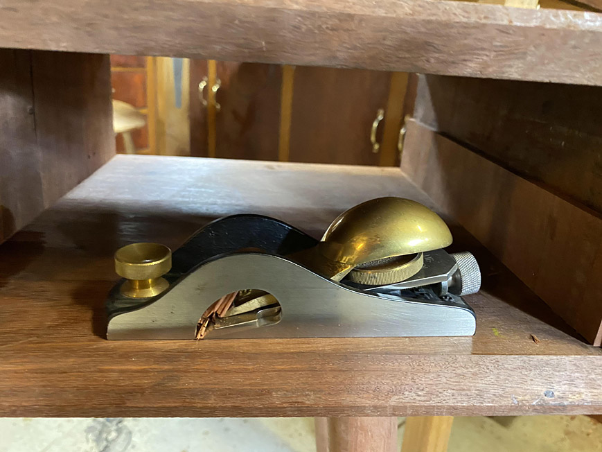
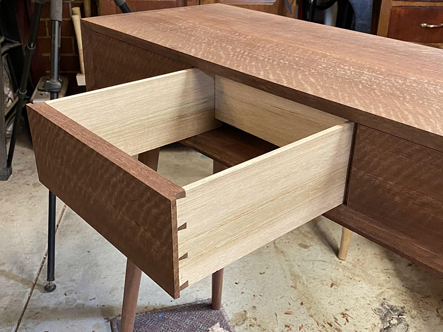
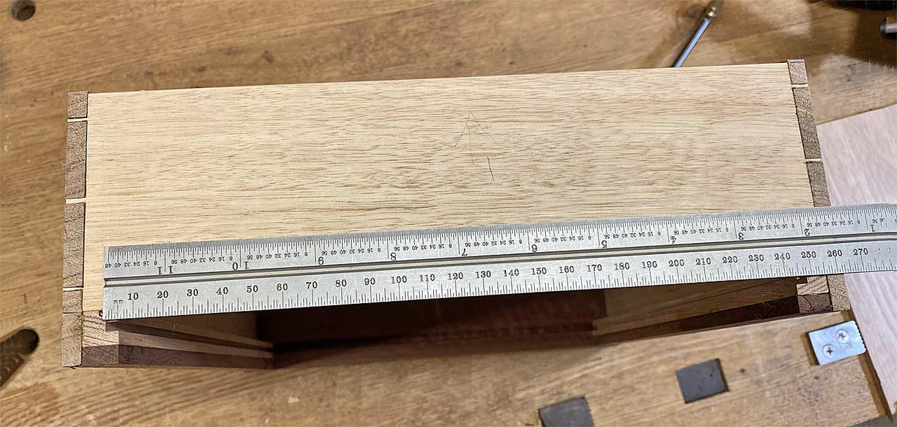
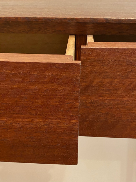
Drawer extension is good - about 80-85 percent ...

21a.jpg


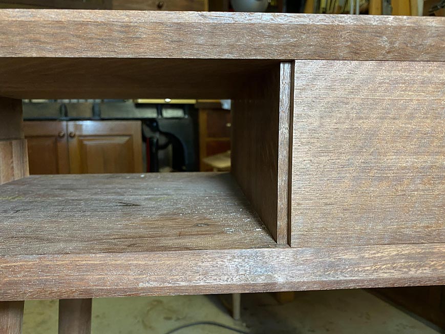
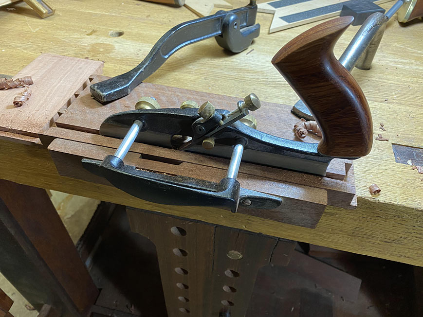
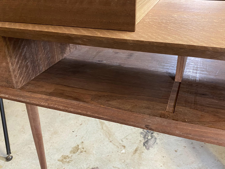
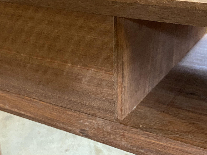
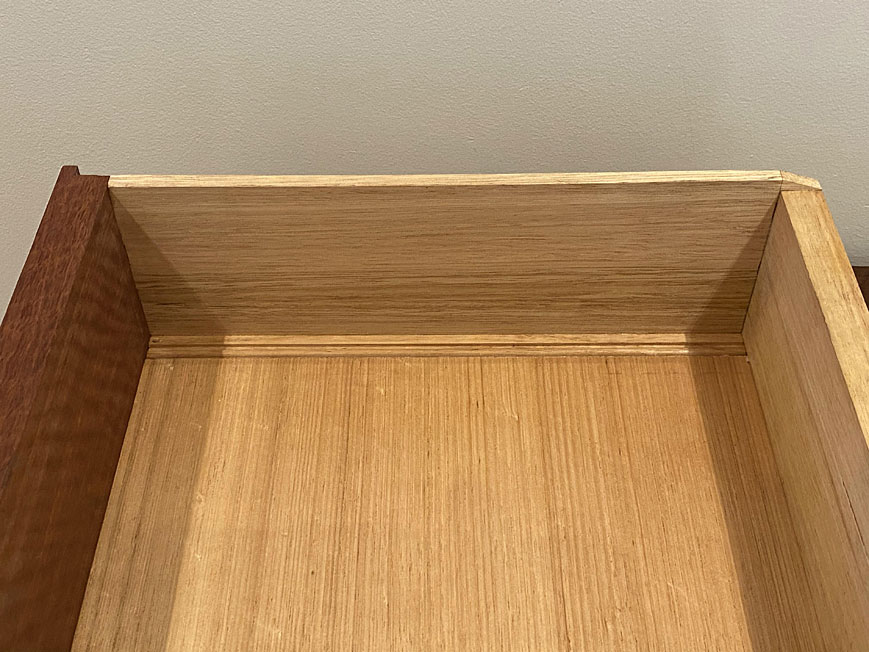
The internal bevels around the case ...

22a.jpg


... maintained a straight edge to the drawer line. Plus the gap between the drawers (about 0.5mm) ...

24a.jpg


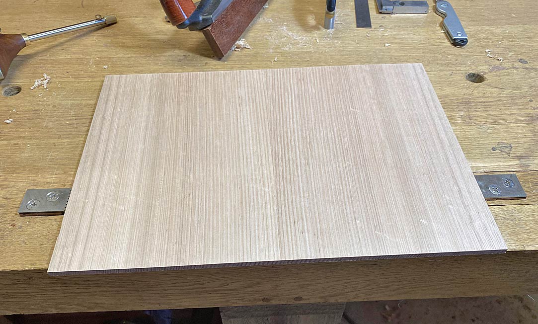
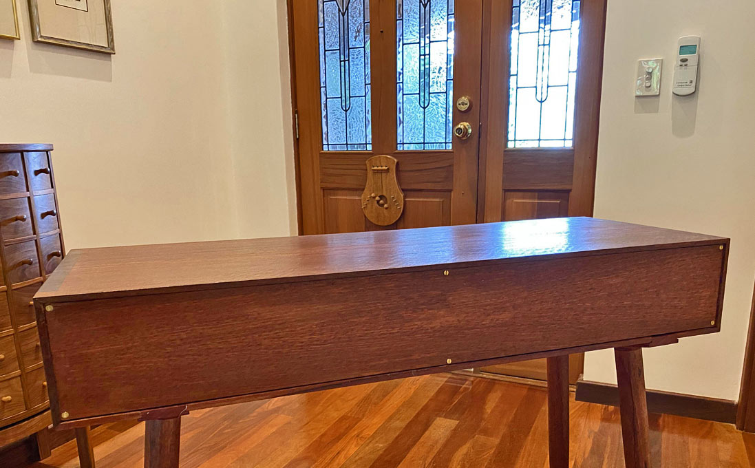
Near-to-last, the case back: this is made from the same Jarrah - one never knows if the piece will end up against a wall or out in the open.

13a.jpg


Someone will ask if the brass screws were clocked ... of course they were! :)

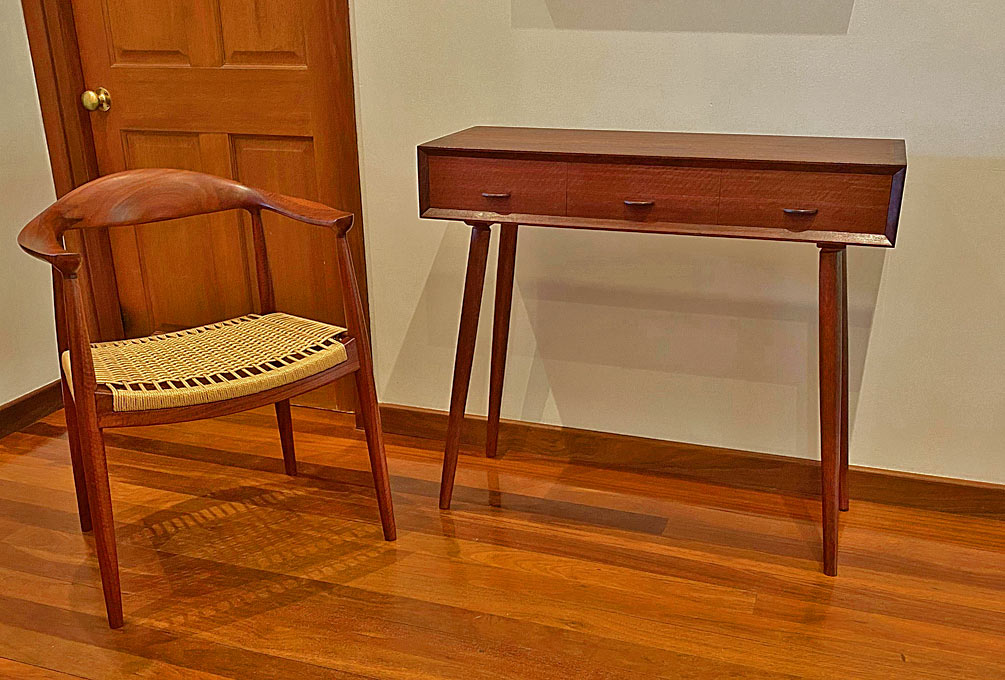
And a final photo to provide some scale. This is taken with a chair I built a few years ago ...

25a.jpg


Thanks for coming along for the ride.

Regards from Perth

Derek
 
Great work, Derek, both at the bench and with the camera. I am sure your niece will be very pleased. I'm not sure how this aesthetic survived the 1950s, though.
 
Inspirational!

I love the way you have made something that resembles the original but is superior in so many ways. As you say, the differences will pass most people by, but woodworkers will know, and appreciate your work.

PS - you will make sure she doesn't stand a bowl of flowers on the top, won't you!
 
Superb piece. Mid Century modern is a great style. I understand how the style survived the 1950s ;)

I remember the Wegner chair build as well - another superb build.
 
Back
Top