Dust / Chip Extraction

UKworkshop.co.uk

Help Support UKworkshop.co.uk:

This site may earn a commission from merchant affiliate links, including eBay, Amazon, and others.
DBT85":23mq88dk said:
RogerS":23mq88dk said:
DBT85":23mq88dk said:
I find moving a hose around between the various tool to be a tedium I would rather avoid. I might want to use the belt/disk sander, drill press, tracksaw, bandsaw etc and because they all pick random bloody sizes for their ports it becomes a pain. I also don't like having the pipe all over the place.

I want to do what Roberto has planned here (though without the loft) but will now probably wait until I build my actual permenant workshop.

Curious to know how you're going to avoid using a tracksaw without a hosepipe all over the place ! Or how you will catch the dust from the drill press ...I think you'll be the first to do that. Also none of those tools that you list are suitable for the size ducting I think you might be considering or even the type of dust extraction you might be thinking of. I accept I could be wrong.

Have you honestly never seen any dx at a drill press?

Honestly ? No ! :D But a quick Google and you live and learn. TBH for me, dust extraction on a drill press never even entered my head but then again I don't use mine that much.

What I think that this highlights for me is that there is no single best-solution for everyone. It all depends on what specific machines we have and how much we use them, the ratio between dust generators and chip generators, are we skilled hobbyists or a joiner by trade which drives the volume of chips/dust we create.

I've been through all scenarios over the years. At the moment, I have a dedicated cheapy vacuum cleaner with PTO installed underneath the Kapex mitre saw. That's a dust generator. I have a combination machine and I use a 100mm hose connected to an Axi 2200 chip collector and that hose is swapped between planer or thicknesser outlets as required. If I had a system of pipes and blast gates just to accommodate those two then I'd have even more pipework on the floor as a trip hazard. So for me, swapping that single pipe over is not a big deal. The same pipe is used when the spindle moulder is in use but since the moulder fence is removed to use the table saw, there is no way that a fixed system of ducting would work.

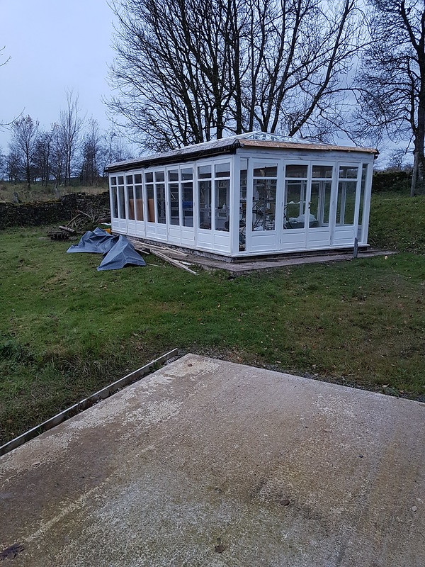
The dust from the table saw on the combi is sucked out by a CamVac and the crown guard by a Nilfisk vacuum cleaner - also with PTO. The latter is pressed into service when I need to use the Domino or TS55 tracksaw. It also means that I can easily take it with me into the house (which I'm renovating slowly from top to bottom) or outside to this orangerie (my Forth bridge project)


You might be wondering why I have both chip collector and a Camvac and a couple of vacuum cleaners ! Historical. When I was making joinery and furniture for a living I had an issue with getting rid of my waste. I could get rid of the chips from the 'chip generators' (spindle moulder, P/T) at a local stables but only if there was minimal dust in amongst it. So I separated my dust/chip extraction problems in my old workshop - hence the Axi and the Camvac.

Since moving, our local tip are perfectly happy for me to empty my dust and chips directly into the wood skip. So I'm not even having to waste bags :D
 
I also dabbled with a cyclone when I was first starting out back in 2006, I recall. I had the idea of making a clear perspex fronted collector box so I could see when it was getting full. It's all in this thread including a description of the implosion when it was first fired up...pics lost sadly.
 
Inspector":2l7h3tnd said:
Stacey I know you put a lot of work in making your system but the straight Tee fittings are a flow killer. If you look at page 61 of http://www.lorencook.com/PDFs/Catalogs/ ... atalog.pdf chart 6a with a 1 to 1 ratio the Tee fitting is the equivalent of 125' of straight pipe. If you can find and replace them with a radiuses 90º Tee or a 45º branch fitting it will improve the flow, gathering more dust in the process. You can 3D print them since you have one.

Pete

I fully aggree, but Screwfix only do a T or a Y and I mean a "Y" (each leg is at 60 degress, not a stright run and a angled leg) and while I have seen 45 degree Y on sale none fit the ducting and none were £3 each, plus this thing sucks.. and I do mean sucks!... I have put the 63mm pipe in a buckey of thicknesser shaveing and its all gone in seconds.
 
Yeah I'm sure it does restrict things and probably a fair amount, but it also does work in practise even with the tees.
 
Deadeye":38raeelm said:
Stacey":38raeelm said:
I had a old Axminster single stage unit that was being disposed of by a school, it sat in the workshop for 5 years then a few weeks ago I got off my buttocks and built a cyclone, run lots of 100mm duct (Screwfix), made blast gates and 3D printed all the adaptors for my tools and today I wired a remote switch into the contactor... Awesome!

Edit: if anyone want to know all the parts used and wants the £D files I am happy to supply.


I'm curious about the economics of 3d printing. People seem to frequently say "I printed it" - which sounds great, but all the prices I see online would make it ridiculously expensive to print a blast gate or Y junction.
What are the real costs of printing a largish part like that?

Sorry, I hit submit before I finished... I printer a 100mm to a twin 63mm adaptor for my table saw (main and guard outlets)

100mm to twin 63mm.PNG

this cost me about £1.50
 

Attachments

  • 100mm to twin 63mm.PNG
    100mm to twin 63mm.PNG
    67.5 KB · Views: 173
There is no way that I will be allowed to have any dust in there ! one half has now all been insulated and boarded out and painted now its over to the other side to sort the same !
 

Attachments

  • WShop.jpg
    WShop.jpg
    73.6 KB · Views: 126
DBT85":385s9w15 said:
Deadeye":385s9w15 said:
Stacey":385s9w15 said:
I had a old Axminster single stage unit that was being disposed of by a school, it sat in the workshop for 5 years then a few weeks ago I got off my buttocks and built a cyclone, run lots of 100mm duct (Screwfix), made blast gates and 3D printed all the adaptors for my tools and today I wired a remote switch into the contactor... Awesome!

Edit: if anyone want to know all the parts used and wants the £D files I am happy to supply.


I'm curious about the economics of 3d printing. People seem to frequently say "I printed it" - which sounds great, but all the prices I see online would make it ridiculously expensive to print a blast gate or Y junction.
What are the real costs of printing a largish part like that?
If you're talking about per part, PLA filament runs about £30 a kilo from what little I just saw. So depending on the part and how solid it is/needs to be that's one cost. The cost of running it would need to be recorded with a smart plug or something.

I think often it's not even about the economy, its about getting the thing you need or want rather than something close and bodging around it. Fairly easily you could make any hose adapter you wanted for example. Just adjust a few numbers for pipe sizes in something like fusion 360 and do whatever it is you have to do to print it.

I really should fire up the one I have in a cupboard. It was my brothers and I borrowed it 2 years ago and that's as far as I got!

PLA... £30 per kilo, I have never paid for that £10 per kilo, who are you buying from?
 
Stacey":2syvh2oc said:
PLA... £30 per kilo, I have never paid for that £10 per kilo, who are you buying from?

Oh that was just a quick search. At that point I'd never actually bought any.

Where are you getting some for £10 kilo?
 
Hi all, bit of an update :arrow: been a tad busy with parents .. one that's broke his leg .. another with CV19 and inlaw that is just barking mad !

Moved over to the otherside of the Workshop ( I really mean our lass's garage ) and insulated and lined it out with 12mm ply, took the advice and decided against putting the camvac in the loft but have opted to enclose it all in a corner in a vented cupboard above the Cyclone unit but my dilemma now is do I run the horizontal 4'' pipework at high level which means the run will be a 1000mm vertical pipe from the cyclone up the wall then horizontally across the ceiling then 2 drops down the walls where I plan to connect stuff OR do I keep the horizontal runs at 1100mm high with it all running under my dado electric trunking and have the connections lower down ... decisions decisions ... photos of works thus far and any feedback gladly received as its all a learning curve for me Thanks in advance Roberto
 

Attachments

  • 20200615_190157.jpg
    20200615_190157.jpg
    145.7 KB · Views: 55
  • 20200615_190202.jpg
    20200615_190202.jpg
    157.1 KB · Views: 54
  • 20200615_190213.jpg
    20200615_190213.jpg
    125 KB · Views: 54
  • 20200615_190240.jpg
    20200615_190240.jpg
    97.5 KB · Views: 54
Went with the latter option.... high level with the thought that if it doesn't work I can always move it lower down which would be far easier later on than putting it higher up ! sealed the 2 x 110mm-100mm adapters for now with some masking tape to try it seems OK but i'm wondering if i'm losing much 'suck' ?

Also wondering if the Camvac would be better on the floor , then the collection tub then the Cyclone at the top ?

Thoughts & suggestions always helpful, thanks Roberto
 

Attachments

  • 20200617_173853.jpg
    20200617_173853.jpg
    463.1 KB · Views: 40
  • 20200617_173758.jpg
    20200617_173758.jpg
    152.8 KB · Views: 37
I think heat build up and air flow in that cupboard will be a problem that needs to be addressed before you do a protracted run.
 
Hi Sunnybob, many thanks for your input ( thats why I posted as I am only a newbie )!

I am drilling a 115mm hole at the top today to push the top 2 x venting hoses from the Cam Vac into to vent outside in the Summer so there is no heat build up and then redirecting them in the winter out of the bottom of the cupboard in the winter to give some 'free heat' in the garage.

Re ais intake into the cupboard I am planning to have a small 300mm section at the bottom left open to let air in

Do you think this will suffice ?
 
Why do you need to let air in? The motors are cooled by the air that they are moving and that air as you have already said is either being vented outside or back into your shop.

As long as its not just vented into that cupboard where it would start to build up I don't know why you would need additional air in that cupboard.
 
Roberto Flintofski":23u3fcqu said:
So that's even better ! It should almost be quiet in the shop then :)
Ha, We always find something to make a racket!

Sadly my DX4000 doesn't have a solitary outlet, the air just kind of disperses out of the lid so channelling that air anywhere is a bit more work.
 
Roberto Flintofski":2ii47ri3 said:
Also wondering if the Camvac would be better on the floor , then the collection tub then the Cyclone at the top ?

I'm far from an expert, but I would think it would be better* with the cyclone inlet in-line with the pipe runs to your machines. The more bends you put, the less efficient the whole setup will be.

*that's always relative, so it might not be worth the effort. I would just try some dust collection to see if what you have works for you, before wasting time striving for perfection. If it ain't broke, don't fix it, right :D
 
Hi Biblu,

That was my initial thought but really wanted it up out of the way so I went with that and will 'suck it and see' I could have done with some kind of 'Suckometer' to try both options 1st before I fixed it all :shock:
 
Hi All,
Bit of an update for anyone who takes an interest..... R/H side now almost complete, chose to just go with the one outlet on the Extraction for now till I see how much of a faff it is to keep swapping hoses ! Just need to put some doors on the Extraction Cupboard and our lass needs to do a bit more painting then hopefully move everything up off the ground ( somehow ) to paing the floor !
 

Attachments

  • c.jpg
    c.jpg
    112 KB · Views: 57
  • a.jpg
    a.jpg
    79.3 KB · Views: 55
  • b.jpg
    b.jpg
    72.4 KB · Views: 53
  • e.jpg
    e.jpg
    69.7 KB · Views: 53
Back
Top