Drilling and Tapping behind a threaded hole (aligning/clocking a tap?)

UKworkshop.co.uk

Help Support UKworkshop.co.uk:

This site may earn a commission from merchant affiliate links, including eBay, Amazon, and others.

Ttrees

Iroko loco!
Joined
18 Nov 2012
Messages
4,914
Reaction score
917
Location
In me workshop
Hello folks
I'm wanting to make a gib-like thing for the quill adjustment bolt on the pillar drill
after reading of someone doing so on this thread
https://www.model-engineer.co.uk/forums/postings.asp?th=128627
That little grub screw beside the return spring has two flats on the thread to engage into a slot in the quill.
Turns out there is quite a bit of space behind the casting,
so have gotten a dead bolt from a door lock, which hopefully might have a good bit of brass, if not then I will likely be making part from mild steel.

I am thinking of taking out that adjustment the screw provides, and creeping up on the perfect fit of the "tongued block",
I would like to tap this block so that it sits tight, i.e ....
so the screw doesn't push the plate away from behind, whatever an amount of one thread of a distance.

Is the answer to assemble again and then simply place the tap into the threads already there
Or is there another way to do this?

Can post some photos later
Thanks
Tom
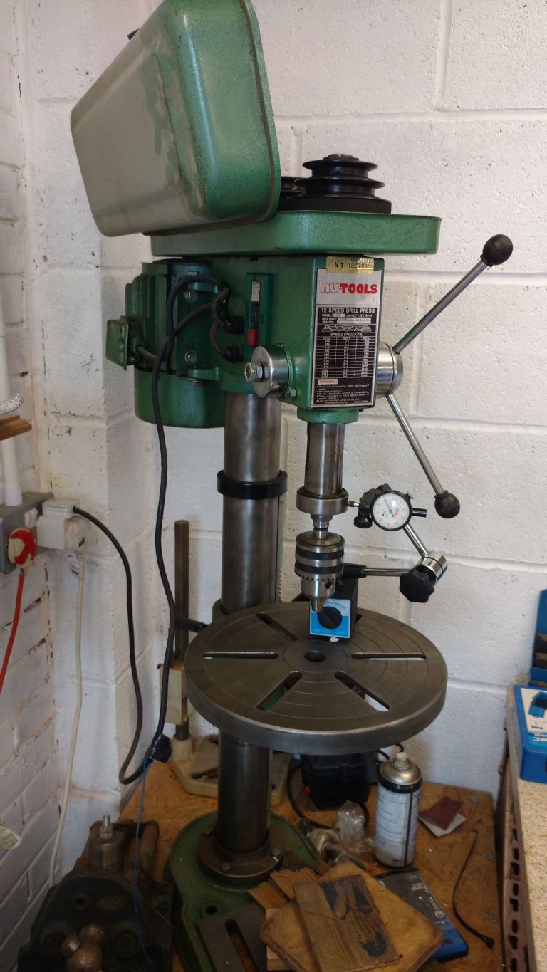
nutool pillar drill
 
Last edited:
If it has two flats on it, you will only ever need to turn it half a turn. It looks like the one in the thread to which you linked had a square end, so worked in quarter turn increments.

The design challenge with it is that the engagement length with the keyway in the quill is too short.

Consider adopting the solution Myford used in the tailstock of the ML7. See part 23 here:
Myford Ltd EXPLODED PARTS DIAGRAM Long key on a free-floating shaft. File key depth so it does not bottom out on keyway in quill.

Note that it must be inserted from the inside before the quill is installed. Fiddly, time consuming and not suited for a factory assembly line, but a better engineered solution.
 
Thanks for the suggestion @ChaiLatte
Seems the Myford has some sort of barrel with a captured gib, which would be the same size
as the grub screw?
I was thinking was something with more surface area, how much I don't know,
suppose the quill won't travel fully and that will have the say in what size it would end up,

Not got around to starting this yet, might get the chance later.
I can at least post a picture of how it looks.
Plenty of space, seems nearly about 20mm of distance for the grub screw to make contact.
Even with any play taken out of the equation, it seems a bit small to me.

Seems odd that I cannot find some term for what I propose,
hopefully this can be answered as it's not the first time that threads didn't match and pushed tapped items apart.

The trouble is I'm thinking I have to make it fit perfectly beforehand, so no grinding afterwards to
align threads.

Cheers
Tom
 
Ttrees,
You best way would be make the block to fit the space you have in the quill and a snug fit to the casting, fit it all together line up the quill and block with the hole, grind a screw to a point screw it in to mark the block take the block out and drill the hole then fit it back in making sure it goes in the same way it did before you marked it.
Doing it this way means everything is square and the thread carries on into the block.

If you get stuck for brass let me know I have a stock of sizes.

Phill
 
@Phill05
Thanks for the offer, looks like I don't have enough brass, but plan b is to make the block
with the brass gib dovetailed, so likely have plenty.

I was planning to do the same job as you say,
but am still faced with the issue of the tapped hole being threaded in such a way,
which could either seperate the block from the flat area of casting behind the quill hole,
or damage the threads in the cast.

Having encountered similar issues in the past, I've had to drill out the threads on the face
and rely on the threads in the block behind to keep tight.
Hopefully that makes sense?

Not started yet, will edit this to clarify in a bit.
Hopefully they will be clear enough, as was having to use my nose 🤥 to take pic
Cheers
Tom
SAM_6005.JPG


Probably don't even need to use brass, but have the following options
SAM_6008.JPG
SAM_6010.JPG


SAM_6012.JPG


There's about 20mm of depth to the quill, so will likely make a block from some 8mm
bits, see if I can get away with using the brass, seemingly best dovetailed with some flats.
Will have to see first how long I can make the gib, blue the slot & reassemble,
hopefully can gain a good deal more surface area and make a bit more solid.

SAM_6013.JPG


Likely will be clearer half way there, and get the block (hopefully brass)
and be it insert or gib if things turns out not so well,
and have it so the fit is real tight, and then possibly start off the threads
through the pre drilled - hole,
(which like Phill, I wasn't going to chance drilling, just an interesting side note to see if some do)
 
Last edited:
Might I suggest that the first thing to measure is the slot in the quill.

Only part of its length ever engages with the current flatted bolt. The bolt is intimate friends with (one side of) the length of the quill travel. They have passed each other by every day since the drill was first assembled. So they have grown old and worn together.

The slot at the bottom of the quill is the run out from the machining process. It is a near neighbour, but complete stranger to the flatted bolt. They have never been in contact so the slot is factory fresh

The slot at the top of the quill is briefly acquainted with the bolt - they have passed each other by once when the machine was assembled and once when you have just disassembled it. Again the slot is factory fresh (delivery mileage only).

If, as a result of use over the years, the working part of the slot has worn (combination of increased width and out of parallel sides - note that the torque reaction would tend to wear one side more than the other), that would be the first thing to fettle and correct. Trying to fit a new key to an inconsistent slot will be an exercise in frustration.

Your terminology is fine - clocking a thread or synchronising a thread is as good a way as any to describe what you want. The reason you cannot find much on it is that it is not a widely practised technique - in general, threads are supposed to be used for either for fastening (holding things together) and linear positioning (e.g. threaded leadscrews). They are not really supposed to be used for spatial positional alignment (dowels, etc. are correct for this), nor the combination of linear AND rotational alignment that you seek.

To do what you want needs close control over both the male and female threads and this is difficult and expensive, even on CNC machines that can know the rotational alignment of everything they produce.

Think how you would position (clock) a lever handle - you'd make the male and female parts any old how and then use a washer between them whose thickness is adjusted empirically such that the handle ends up in the right place.

A 'solution' to your issue is to use a combination of left hand and right hand threads, like a turnbuckle - the hook (key) can be made to point in any direction for a set length or the same direction for any length. The engineering is sound but it is totally impractical.
 
You seem to be over complicating this. If you make your gib to be a good fir, then just drill a hole in it about 2mm in diameter to line up with the screw hole. Now drill a similar hole in the end of the adjusting screw and fit a steel pin in it. Doesn't matter if the gib hole is exact, the only purpose of the pin is to stop the gib falling out. Pressure will be applied to the gib by the flat face of the adjusting screw around the pin. When it comes to assembling it just use some thick grease to hold the gib in place while you put the Quill back in.
 
Thanks folks
Chailatte
I don't think the walls of the slot in the quill has much wear, as the flats of the screw (I'm guessing)
was never in contact.
As said I'll be bluing the slot to find out how large I can make the gib,
so can test the walls also.
Scraping work might need be done anyway if the quill doesn't retract fully.

Not being an engineer, I am not concerned about speed or practicality,
so can spend more time than what makes sense, i.e assemble, blue, disassemble again kinda thing.
I have every file imaginable for the job BTW, can make scrapers , but no L/H taps.

I understand I can remove(grind) or add material(shim) to align threads, but being a OCD kinda fella
I wish to know the solution to this problem, not just for now but for again.

And Fergie 307
I did originally think of "turning" a screw to a smaller diameter on the end, and drill the gib to fit,
but with such a small screw, would be a bit wimpy in my eyes.

I still have that option with a more practical screw, if I muck up the threads...
possibly attempting to get a thread or two started when assembled and tapping the block through original tapped hole,
(the hard way accounting for the worked deformation and burr, and disassemble a few times)
I have no qualms about being a stickler.

Surely there must be some application where folks do this frequently?
Not so keen on tapping before I find out.
Plenty of time to wait for an answer, so will be seeking the job, if even to study utoob
on a not how to do it basis to try glean some more information.

Thanks for your suggestions, hopefully I can get by doing it the simple way,
even though it might not be so simple in reality, lol
Seems I've got my work cut out being an ignorant so and so, but honestly seems the best way to my eyes.

Tom
 
Not sure i understand what you are trying to achieve. If you line up the threads then the screw will simply pass through and will not bring the gib into closer engagement with the quill.
 
Not sure i understand what you are trying to achieve. If you line up the threads then the screw will simply pass through and will not bring the gib into closer engagement with the quill.
Sorry I haven't got started yet to explain,
Not concerning the gib, my question is regarding tapping the block (no metal cut yet)

My question is, whether I can place the tap into the existing threads, and tap the block behind it
without destroying the threads.

It would be the last thing done, as the block needs to be tight up against the casting.
See cardboard with grease transfer of the flat portion behind the screw.
I wish this block to sit tight against that, and not need to use a shim if the screw might happen to
push the block away from the casting.
(which would only be possible if the quill was taken out again, as it would damage the threads otherwise)

Tom
 
The srew serves two purposes. Firstly it stops the quill rotating, secondly it gives you a crude way of eliminating any play between the quill and the bore in the casting. Inroducing any fixed block will necessarily rob you of the second function. Introducing a gib is an excellent idea as it will spread the contact area and give you a better adjustment. Gibs secured by pointed screws in coned recesses in the gib are the norm on most machine tools. My suggestion of using a pin is merely an adaptation of this idea in order to facilitate assembly. Nothing wimpy about it, Im sure this wouldnt have survived as the standard method of doing it for several hundred years if it didnt work. I would certainly try this first as its very simple and could be done in a few minutes. If it doesnt work satisfactorily, then you can make it more complicated.
 
The srew serves two purposes. Firstly it stops the quill rotating, secondly it gives you a crude way of eliminating any play between the quill and the bore in the casting. Inroducing any fixed block will necessarily rob you of the second function. Introducing a gib is an excellent idea as it will spread the contact area and give you a better adjustment. Gibs secured by pointed screws in coned recesses in the gib are the norm on most machine tools. My suggestion of using a pin is merely an adaptation of this idea in order to facilitate assembly. Nothing wimpy about it, Im sure this wouldnt have survived as the standard method of doing it for several hundred years if it didnt work. I would certainly try this first as its very simple and could be done in a few minutes. If it doesnt work satisfactorily, then you can make it more complicated.

Sorry I haven't got started yet to explain,
Not concerning the gib, my question is regarding tapping the block (no metal cut yet)

My question is, whether I can place the tap into the existing threads, and tap the block behind it
without destroying the threads.

It would be the last thing done, as the block needs to be tight up against the casting.
See cardboard with grease transfer of the flat portion behind the screw.
I wish this block to sit tight against that, and not need to use a shim if the screw might happen to
push the block away from the casting.
(which would only be possible if the quill was taken out again, as it would damage the threads otherwise)

Tom
I suspect the answer is no. To do this successfully you would need to have the two parts clamped firmly together when originally cutting the thread. The tap wont get enough purchase on the existing thread to cut through the second part, and will probably strip the existing thread. If you really want to do this then I would clamp the two firmly together then drill the hole out to the next available size and retap it. But I think your approach to this is flawed anyway. Can I ask if there is actually a flat machined surface in the casting at the back of your threaded hole? I cant imagine why there would be, and If not then how is you block going to seat squarely.
 
Good point @Fergie 307
I hadn't noticed that it also stopped the quill rotating.
Suppose the original idea of a brass insert is the wrong way to go about it,
and I will not be making a blind hole in the block so,
in favour for a gib rather than a rigid insert.
That means a wee bit more flat for wear so.

If were on about the same thing here regarding what I propose....
I was suggesting the pin would be a bit wimpy, especially as I hadn't figured out what you've just told me regarding the function of the slot was to stop rotation of the quill!

Regarding wimpy, I'm thinking the screw would need to be about M10 in order to have a substantial enough pin which would be set/mortised into the gib.

Thanks for the enlightenment on that one.
Cheers
Tom
 
I suspect the answer is no. To do this successfully you would need to have the two parts clamped firmly together when originally cutting the thread. The tap wont get enough purchase on the existing thread to cut through the second part, and will probably strip the existing thread. If you really want to do this then I would clamp the two firmly together then drill the hole out to the next available size and retap it. But I think your approach to this is flawed anyway. Can I ask if there is actually a flat machined surface in the casting at the back of your threaded hole? I cant imagine why there would be, and If not then how is you block going to seat squarely.
This is why I said the tapping would need be the last thing done,
i.e block and gib assembeled (after being predrilled) to attain the force required for the tapping.

If you look at the pictures, you can make note of the transfer to show a flat surface,
whether it's 90 with the screw is another matter,
and will be interesting to sort out if it isn't! lol

Thanks
Tom
 
If you wanted to use a block then the simple way would be to put a threaded stud on your block, drill out the thread in the casting then pass through the threaded stud and secre it with a nut. But as I say I would use a gib, because it will sit in the slot it can probably be quite a decent length, so giving you a better action than the small contact area you have at the moment. I have done a similar mod on a big old sealey floor stander I have. I used a strip of steel to make the gib rather than brass. And the pin is cut from an old 4mm twist drill. This on a machine where the slot is about 11mm or 7/16 wide from memory. The pin stops it falling out and also stops it rotating. Providing everything is a reasonably snug fit, and your bearings are ok, then the torque on the quill is not that great.
 
Jjust to explain further. I started out making a conventional cone and cup type arrangement but found that the gib refused to stay put when assembling it. The quill on mine weighs about 25kg, so not much fun fighting with it. Using a pin enabled me to hold it in place easily whilst inserting the quill.
 
Made a start on making the block
Didn't need to blue the slot and used a well fitting marker simply placed into the hole.
Might have to continue the slot a bit further, but not much,
Seemingly loads of space to make the gib tall.
As soon as Fergie 307 mentioned the grub screw also acted as a stop for rotation,
my first ponderings went out the window, potentially saving some time or materials,should I not have copped that! (cheers Fergie)
Going to weld up some 8mm plate about the size of the cardboard, and leave a 5mm gap between.
Still aiming for the screw to do both jobs without enlarging the existing screw hole and tapping both together, but that is what I'll have to do if I cannot find out how to do this, and cross me fingers it might work.
No bother I suppose, and maybe a pin might come into play then,
that will be a consideration now, so not going to do anything yet regarding that.
Cheers

Tom

SAM_6018.JPG


SAM_6022.JPG
 
I think the problem you will have is that even clamping the two pieces together and tapping them, you will still find that when you put a screw in the two pieces will rotate slightly relative to one another. This is because there is inevitably some play between the male and female threads. As ChaiLatte says, this is not really what threads are supposed to be used for. So I don't think your block will be held tight against the back of the hole by this method. The other issue is that if the block were the correct size to eliminate play then practically speaking you won't actually be able to install the quill past it. The clearance to eliminate any discernable play will be tiny, well under a thousandth of an inch probably. Very difficult if not impossible to install it in the face of that sort of clearance. That's why this sort of thing, like the gib strips on a lathe, are always installed loose, then tightened to the correct clearance once the components are in situ.
Just trying to save you a lot of work and potential frustration.
 
To illustrate the point I am making get a bolt and run two nuts down it. Bring the two nuts together you will see that you can either have them locked together, in which case the bolt won't turn, or if they are sufficiently loose to allow the bolt to turn between both at the same time, then they aren't locked together. You can't have it both ways.
 
Before you go any further at all I would check the bottom of your slot in the quill. It appears to have regular ridges in the bottom. Almost certainly cut on a horizontal mill, and looks like the feed rate was probably too high to achieve a good finish in the bottom. In fairness to the manufacturer it looks like the main purpose of the screw is to eliminate rotation, so it would be the sides of the slot that would need to be accurate, not necessarily the bottom. You need to establish whether your block, shoe, gib whatever you want to call it is actually going to slide smoothly on that surface. Try sliding your plug pin up and down it. If it catches at all on those ridges you are going to have your work cut out.
 
Back
Top