Cutting a groove at an angle with hand tools.

UKworkshop.co.uk

Help Support UKworkshop.co.uk:

This site may earn a commission from merchant affiliate links, including eBay, Amazon, and others.
sunnybob":38efjl4n said:
Recessed tenon?

Of course, thats only bluff, you all know I know nothing about REAL woodworking =D> =D> :roll: 8)

You've lost me there Bob, a tenon that somehow fits into the rest of the wood?

No, don't get it. Could we have a drawing? And maybe a series of YouTube videos? :D :wink:
 
I was going to start this by saying that it looks at though the prize goes to Doug B but he's beaten me to it with his own demo!

However, should you be interested, this is what I've just done.

The plane was a Veritas plough fitted with either a 3/16" or 1/4" blade. The wood was a piece of Zirbel pine about a foot long and measuring 4" by 7/8" thick. I found that this can't be done with a narrow piece of wood because the rods which connect the fence to the body hit the wood, preventing any chance of planing. So if you did want narrowish pieces, it might be an idea to cut the grooves top and bottom on a 4" or so piece and then rip it into narrower bits.

The wood was planed and carefully checked for surfaces being square.

I realised that I'd want a shallower angle than on my first attempt (32°) and settled for 15° which looks just fine. I gauged a line about 1 - 2 mm from the bottom on the inside of the piece and used a sliding bevel set to 15° to make a nick on the outside, then gauged from that nick along the outside and joined the two gauged lines using a ruler. In complete contrast to Doug's efforts I held the wood in the vice with the angled bottom uppermost and the groove on the bench side.

Then it was a matter of creating a bit of a flat with a paring chisel for the plane to work on. The key thing to the planing is to be working as near parallel to the lines on the end grain as you can so that you can sneak up on it. Once you think you're done, check the planing by standing the piece on the newly planed edge with a combination square behind it and if the height is the same all along, you've got it.

Now to the ploughing the groove: fence on sloped surface and away you go. Well it's not quite as simple as that as DW points out. The blade has to be retracted quite a way from the bottom of the skate to make the first shallow nick on the bottom of the groove. Then it's a matter of increasing the depth of cut a little bit at a time until you eventually have the whole blade cutting. Once you've got into the whole groove it actually becomes easier than planing a normal groove. This is because the plane has three points of contact: the fence on the sloped surface, the bottom of the skate on the bottom of the groove and the far side of the skate on the upper surface of the groove. Keep the depth stop out of the way and plane until you are happy with the result.

So thanks again to Doug and everybody else who took their time to think about this. I think that MikeG's solution looks quicker, especially if you had to do lots of such grooves. However, you obviously wouldn't get full supporting contact in the groove, which probably wouldn't matter for most jobs but might for some.

Andy.
 
The corner cabinet here is the second to last cabinet I made for this kitchen. This cabinet had the joint that we're talking about here and I cut it in - the doors on these cabinets are solid (I should've known not to make the panels full thickness, but they're full thickness and saved only by soft close hinges).

https://i.imgur.com/EeAOUKO.jpg

Because of that, I wanted a full fit joint to the corner - I have pictures of the joint somewhere, but they're lost on an old PC that's quit working between then and now.

The sides are ply, but oddly, I decided at this point to make all but the door entirely with hand tools (even cutting the ply - it's good ply - mostly wood, little glue, no real problem working it by hand). Everything is dado or M&T because i'm not smart enough to know where you could get away with shortcuts on something like this, especially when you live with a notorious cabinet overloader and door slammer - my wife)

Long story short, i needed a solid joint both sides and on the end so that the grip would be good and did what I mentioned above, but by hand (rabbet plane until the joint was flat and then plow to depth. mark ends on depth because the off side of the cut is low and the depth stop won't work right.

I could've done this with a fixture at the time (I had a router table), but I think it would've taken me longer to figure out than it took to do it (less than half an hour total).

I made plow irons and a dado plane the thickness of half inch ply (something slightly less than half an inch) and will never fight a router on this kind of work again.
 
All you need to do is calculate the angle, make a fence at the complimentary angle, and then use this to saw away the sides of the groove. Remove the waste with a router plane.

EntryHallTableForANiece8_html_3d341286.jpg


It would be similar to establishing the boundaries and then removing the waste for a sliding dovetail (where the sides are angled).

Regards from Perth

Derek
 
But Derek, it was trying to calculate the angle that nearly made my head explode (you should have seen the diagrams) and so I sensibly gave up before the men in white coats came and asked the question on here.

Based on what Doug said, I did as described above. The beauty of that method is that you just have to tilt the end piece (in the case of the tray project) at an angle you like the look of, quickly put a roughly horizontal pencil mark on, formalise it on the sliding bevel and away you go with no geometry-induced brain ache.

Incidentally, as a postscript to the above, I had a go today at cutting the dovetails on the ends of the side pieces. I watched Matt Eastlea's video on marking them in, found it a bit complicated and realised that there was a slightly simpler way of achieving the same result but more of that tomorrow. The results would have been brilliant but as usual my sawing/paring let me down, especially with having to saw unusual angles. So I've got to make some new sides and start again.
 
Further to the angled groove there is the matter of the unusually shaped dovetails on the side pieces.

Here's Matt Eastlea's explanation. He starts the marking up at about 6:00 mins. He's already cut the angle on the end and his explanation, while obviously right, I found to be complex.

https://www.youtube.com/watch?v=NhBgHB_i9Ds

Then the penny dropped: it's complex because he's already cut the angle on the end!

If you start with a normally prepared board with the ends square to the sides, the task is really simple and easy. Here's the kit you need:

Angled Dovetails exp.jpg


All I had to do was knock up two dovetail guides from scrap, one at 1:8 and the other at 1:6. Mr Eastlea points out that you need these to counter the optical illusion produced arising from normal dovetails being up against the angled end. You mark 1:6 on the lower side of each dovetail and 1:8 on the upper.

Assuming the end is square to the sides, mark the angle in pencil twice, the gap between being the length of the dovetails. Then working from one side to the other, mark the heights at which the ends of the dovetails cut the end angle. I chose 1/8", 3/4", 1/8", 3/4",1/8". The key thing is that you are measuring the distances not on the angled line but as spacings from top to bottom but they are obviously spread i.e. displaced laterally until they intersect the angled line. Then you just take your new jigs and mark in two lower lines at 1:6 and two upper at 1:8. Thus the fumbling about with a sliding bevel is eliminated.

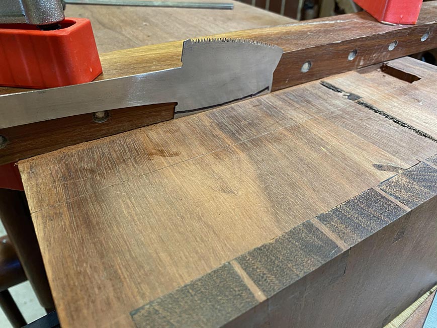
Then you can cut the end slope. I also cut a 1/16" rebate (see middle bit of wood in pic.) because it really will help with marking the pins and the grooves for the sides (taken from the groove in the sloping end piece) but that is a matter of choice. The pic above is a bit more illuminating than my explanation. (If you click on it, it becomes a bit bigger and the detail is better.)
 

Attachments

  • Angled Dovetails exp.jpg
    Angled Dovetails exp.jpg
    63.8 KB · Views: 126
Back
Top