Build your own simple mobile machine base (with Photos)

UKworkshop.co.uk

Help Support UKworkshop.co.uk:

This site may earn a commission from merchant affiliate links, including eBay, Amazon, and others.
I think they are all valid comments. The rear outriggers never cause me a problem as they are all up against a wall and as has been said the bandsaw front ones are under the table so less of a problem. However, the morticer front legs do stick out a bit at the side. There are enough bits of machines poking out above to stop me walking too near mine but that might not be the same for everyone. I will add these point to the first bit of the build to highlight them as things to watch out for.
I am also conscious of the fact that people seeing these frames might come up with a variety of better ways to build their own mobile bases changing and improving the design to suit. I think the main thing was to encourage people to think about how they could build their own showing how I built mine. This information plus the added contribution of the forum members should allow people to design and build a better designed stand than I have.

Nigel
 
Can't fault the workmanship and application Nigel, just something from my own experience I noticed. I have mobile bases on all of my machines too (purchased rather than fabricated). The heavier ones have suitably uprated bases to accomodate the heavy machine. Unfortunately, the heavy base incorporating the castors and brake protrude beyond the work table. The problem I have is, having a smal workshop the bases take up quite a lot of floor space meaning I can't move the nachines closer together. They also stick out quite a way from the wall. So, after my initial calculations I was not able to site the machines as I had originally planned. My error of course, just something for others and me to be aware of in the future.

If you have the luxury of plenty of space then I don't think your design will have any negative aspects.

David
 
Sometimes when you are staring at something you just cant see it! - Sorry David, that comment is not my response to you - it's a note to me!

This is now a proper response to you and the other good people of the forum who took time to point out the trip hazard.
When I posted the pictures at the beginning of the topic, I wrote that I had made THREE bases and showed pictures of three machines on bases, but actually only included photographs of TWO bases without machines and it is these bases that I now recognise that everyone is looking at with the wide outriggers etc. I dont have a picture of the Morticer base before it was fitted. In my other post that started this one on my Sedgwick rebuild, I was going on about machine stability but I notice I have made no mention of this here and simply went straight into how bases like this are made!

The key is in picture (4) and (7) on page 1 A normal base looks like the one on the morticer in picture (4). Granted the legs do stick out a little but so does the table of the morticer and the handwheels and the reality is that you don't end up near the bits that stick out when they are in use. They are not nearly as wide as the other base photos. The footprint of the morticer base is only a couple of inches bigger either side than the sheet metal base and not too different from the overall machine footprint above it. This sort of base is what you would normally make where machines are already fairly well designed and stable. I'm no expert but most of the machines aimed at the hobby end of the market are already fairly stable and not designed to be bolted down. Presumably to comply with CE regulations.

The other two bases are a different matter and are designed to address an additional factor! The bandaw and planer thicknesser I have are industrial machines, primarily aimed at a different market and have been designed to be bolted down. I have seen similar machines on wooden bases/pallets etc and these solutions are all better than leaving the machine completely free standing. I have also seen pictures of a Sedgwick planer / thicknesser like mine with 4 revolving castors fitted where the hold down bolts are meant to go! This is dangerous on three counts, it raises the centre of gravity considerably on four revolving, wobbly castor which can actually reduces the machine footprint, does not support the machine table properly when heavy loads are applied at the ends and this arrangement does not stiffen up the base, quite the opposite. I noticed the sheet metal base does twist noticeably when it is not bolted down on a the Sedgwick PT255.

I don't work in Health & Safety (frankly, I occasionally get as frustrated as most with some of the regulations), but equally I don't want to see people hurt themselves either. I am not a professional woodworker, but like many I am attracted by the build quality and value for money offered by some of the second-hand smaller industrial machinery. Like many, I don't have a lot of space though and need to sometimes move things around to use them.
The extended legs on the bandsaw and planer bases purposely address the safety/stability issue whilst mobilising my particular machines. This is something a normal store bought base would not do for my particular machines. Like most things in life, its a bit of a compromise though. Yes, they do poke out a bit in places, but I have tried to design both of mine to still be a little less than the tables they support or the machine controls so actually walking or moving close to these parts is not a problem in reality. I think the important point is not necessarily to copy my bases but to think what you need in your situation and tailor your design to suit.

I am sorry if I have unintentionally misled anyone at the beginning of the topic (I will edit and fix it though) but I took the original set of photos on the build of the first base to help me remember what I needed to do for any further ones. I did not start out with the intention of publishing these.

So a NORMAL base would look like this (Axminster Morticer)
06MorticeMobileBase-sf.jpg


And the same design tailored for my Sedgwick looks like this
06 Sedgwick Mobile Base.JPG


The Bandsaw base is a real special to address the unusual design of the Mini Max S45

I appreciate all the feedback so far.

Nigel
 

Attachments

  • 06 Sedgwick Mobile Base.JPG
    06 Sedgwick Mobile Base.JPG
    183.1 KB · Views: 25
  • 06MorticeMobileBase-sf.jpg
    06MorticeMobileBase-sf.jpg
    101.5 KB · Views: 25
Hi, Nigel

I think they look fine, most machines have overhanging tables, so tripping won't be a problem.
Can't see what they are complaining about the wide part is at the back.

I put wheels on my kitty Bestcombi by bolting wheels to the sides and fitting a bracket for lift bar.
I have to move my machines about as I only have a garage to work in.

Pete
 
Racers":2x0ju6w7 said:
Hi, Nigel

I think they look fine, most machines have overhanging tables, so tripping won't be a problem.
Can't see what they are complaining about the wide part is at the back.

I put wheels on my kitty Bestcombi by bolting wheels to the sides and fitting a bracket for lift bar.
I have to move my machines about as I only have a garage to work in.

Pete

We were not complaining about anything?? merely an observation, which if you took the time to read, Nigel the original poster acknowledged identified and responded to. How you work your space is quite rightly down to you, perhaps you have enough space or not too many machines on bases to cause you angst?

I trust the point is now clarified?

David
 
O/K I didn't mean to up set the group, who you seem to be the spokesman for.
I got the impression that it was a problem.

I think they are very good stands.

Pete
 
I'm not a spokesman for any group, I speak for myself.

If you have the impression of a problem, that's for you.

I'll say it again, merely an observation.

You may even read that I complimented on the build quality of the stands.
 
I have now amended the initial part of the topic, adding new photos and comments in the beginning to hopefully be a bit clearer on options and will complete the rest of the topic over the weekend. Hope it helps.
With the amount of snow currently falling in the part of Scotland where I live, it looks like I wont be doing much else this weekend!

Nigel :roll:
 
Part 2 - Making the stand

Having worked out the size of machine base to be accommodated, I would start by cutting the rear piece to length (cut it slightly oversize at this stage), then follow it up with cutting the basic parts for the sides and lastly a front section where the feet will later mount. You can lay it all out on the floor of the workshop. Then grab something to drink and ponder and admire your work. By this stage, you will probably start to get a better understanding of how it all fits together.


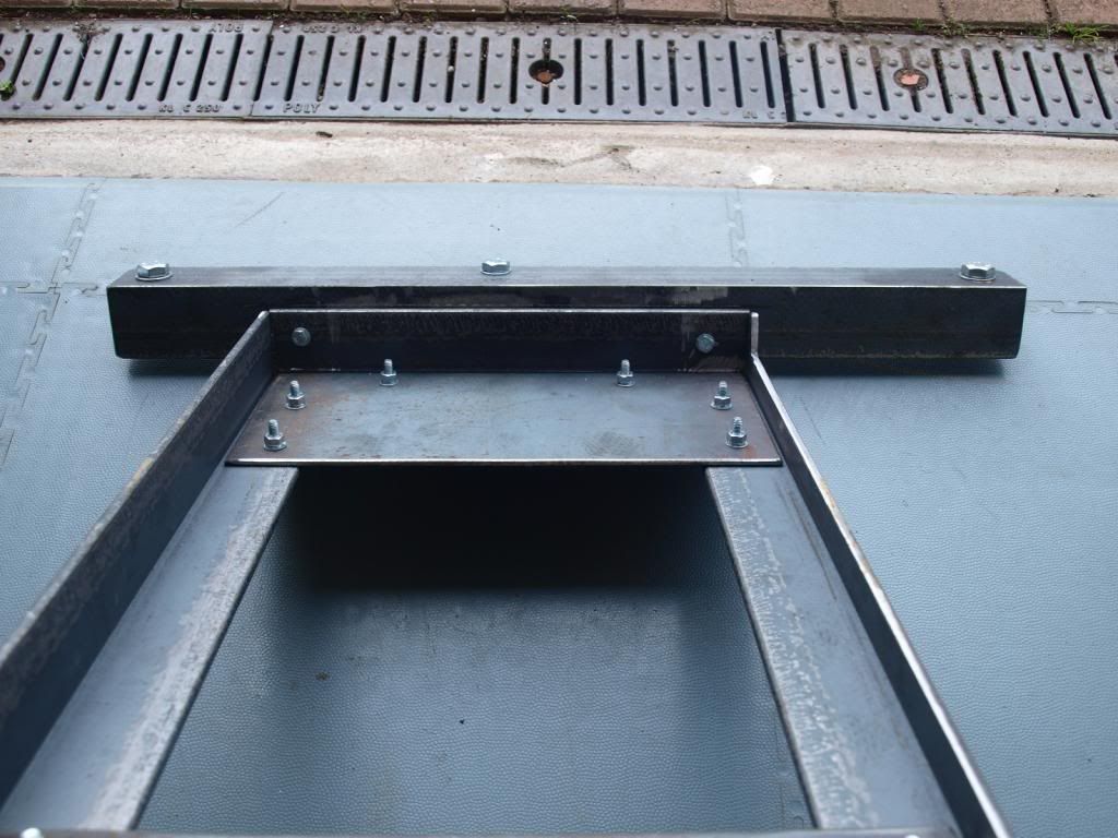
(10). This shows the top inside looking towards the rear all bolted together temporarily for welding, bolts will then be removed
Centre Rear SF.jpg


(11). And this one shows the top inside looking towards the front of the stand all bolted together temporarily. Note the front part of the stand has been raised up by 15mm to allow the lift bar to hook into the front of the stand when finished.

10CentreFront_zps57b7d387.jpg


You will probably start to see that the front has two pieces of angle, one is used to close the rectangle or square central area, the other to form the front support, sitting a little higher up than the rest of the base.
Now when you look at the next two photographs, you should get a much better idea of how simple it is


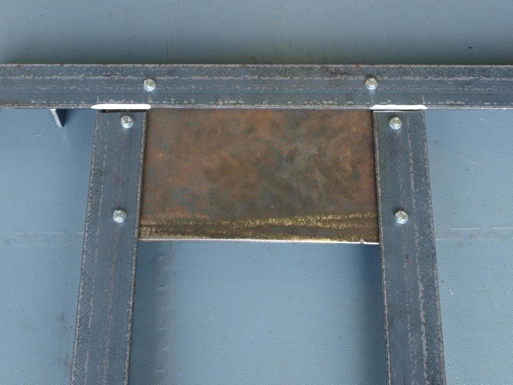
(12). Rear underside before welding here:

UndersideRear_zps2766b283.jpg


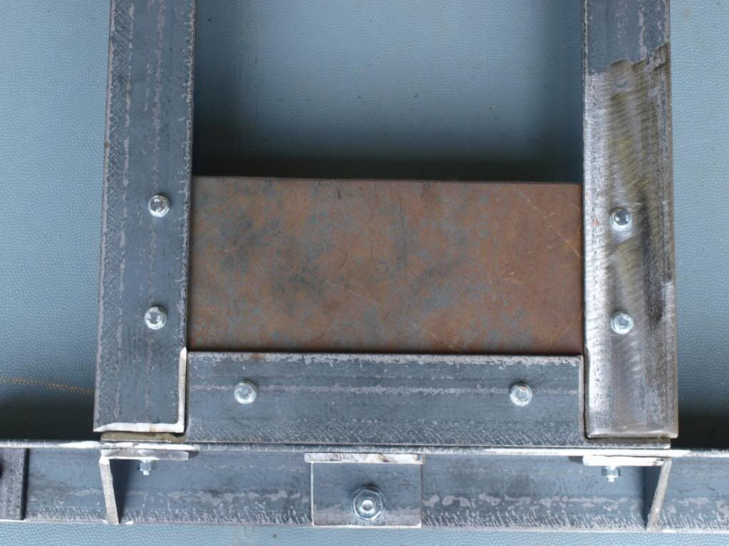
(13). And front underside before welding here:

Undersidefront_zps6cbe0fc1.jpg


Don't worry too much about the additional parts for the front as I will cover this in more detail. Also don't worry about small gaps between parts as they will be filled up when welded, its not fine cabinetmaking here.


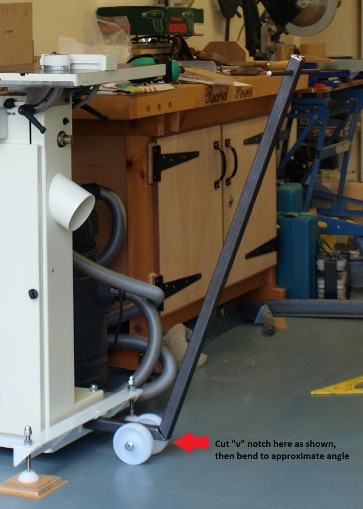
(14). To join the side "L" section to the back "L" section at 90 degrees and keep the area flat, you need to cut a square section out of the bottom of the "L" to fit into the corner as shown below (Red Arrow). If you are finding this hard to visualise, refer to picture (12) above where the top right shows the finished part bolted to the rear section in the direction of the Red Arrow. The cut out shown by the yellow arrow was only needed on my bandsaw base to clear the door and allow it to open. You also need to grind a "V" shape chamfer the two part meet on the underside at approximately 60 degrees (30 degrees per side). you need to create a "V" shape wherever two surfaces join or butt together flat. If they join at 90 degrees, then they are fine for welding without this feature (I hope this is all making sense). You need to cut four areas like this in the centre of the frame. The photographs show two rectangular plates bolted to the Mini Max S45 bandsaw frame, but you could use smaller triangular plates just as effectively as I have in the Sedgwick frame in picture (4) on page 1.

CornerJointDetail1-Arrow_zpsc63ad0d7.jpg


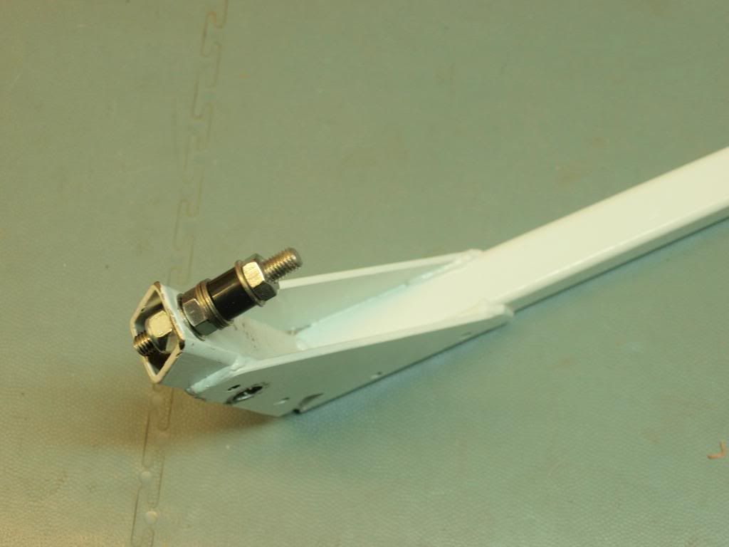
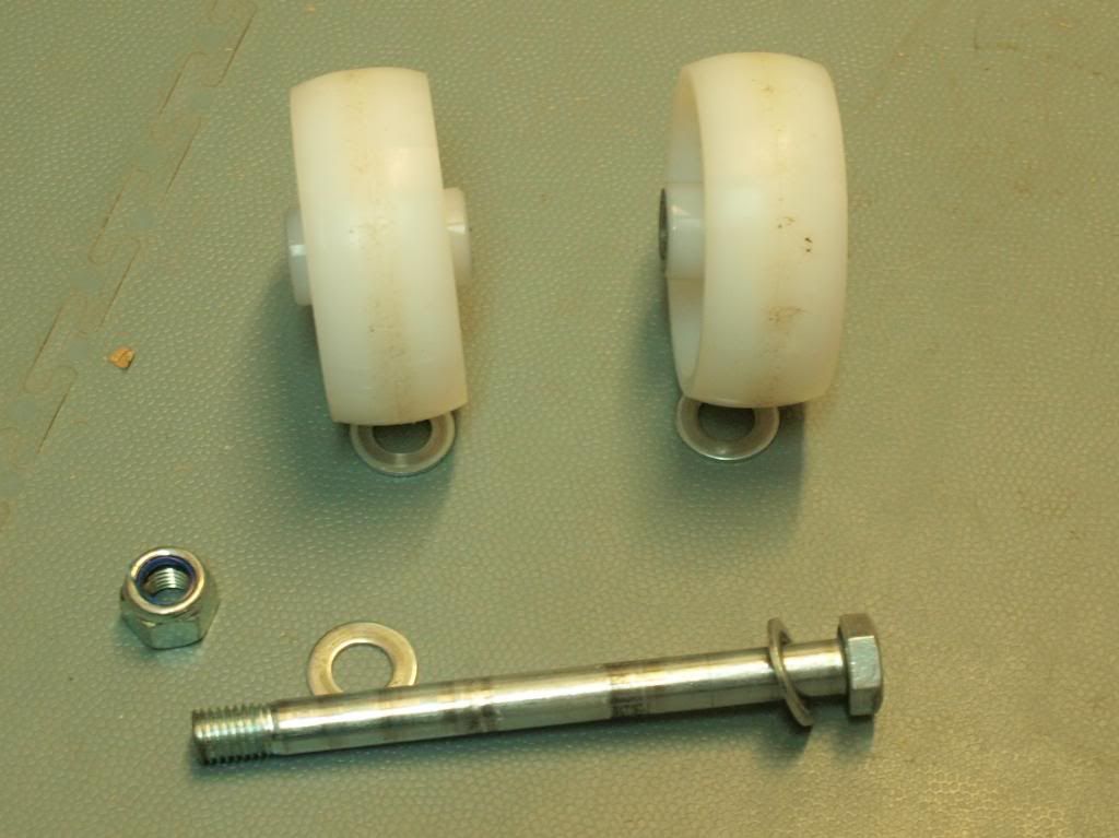
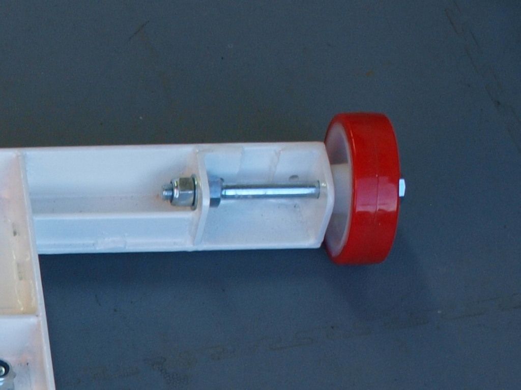
(15). Axles - The arrangement for the axles is the same for all the stand variations. You can shorten or lengthen the rear wheel outriggers to suit your particular machine / requirement. To keep it compact, you can shorten these axles even further than the one already shown. Before you start, I recommend you purchase the bolts that are used for axles. For the 100mm Nylon wheels I purchased, I needed a 10mm axle. In this arrangement, you can use two M10 bolts, zinc plated or if you are feeling particularly flush, Stainless Steel. It is important they are bolts (partially threaded) and not machine screws (fully threaded). The longer bolts I used were 170mm long, but you can tailor the length as I have said to suit you particular needs. In addition to the two bolts, you will also need 8 off plain M10 washers, 2 off plain M10 nuts and 2 off Nyloc M10 nuts. The axle arrangement is shown in the picture below. When constructing the frame, you position the brackets to suit the wheel width in the centre axle area, with the thread being used to adjust the amount of float allowed for the wheel. As the frame wheels are not constantly turning, you don't need expensive wheels with bearings. A washer is fitter either side of the wheel and between the frame and each nut.

15AxleFinishedSI_zps0da8f84e.jpg


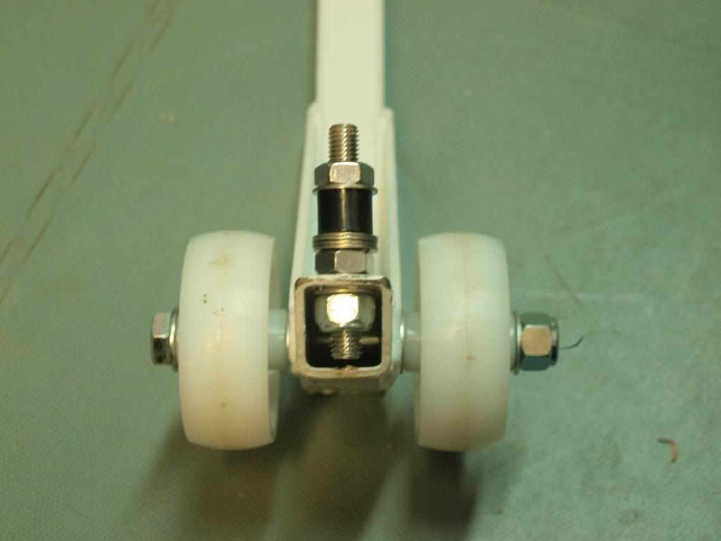
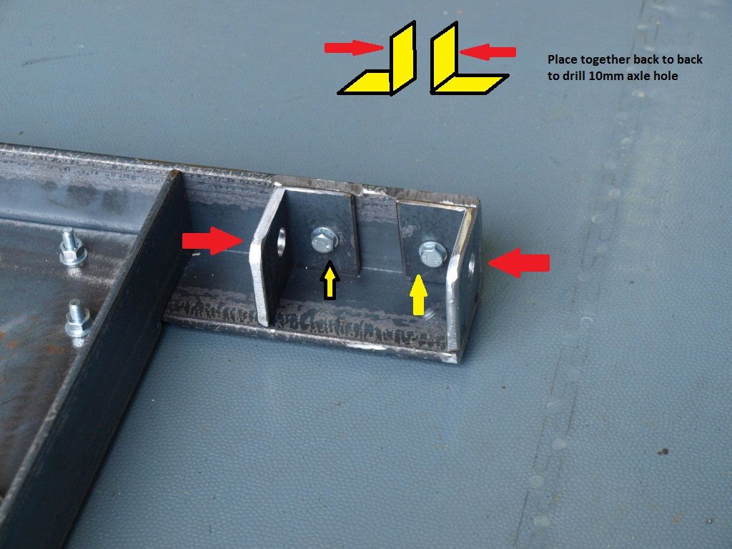
(16). Cut two small "L" shape sections similar to those shown from a piece of angle. Place them back to back to for a "T" shape as shown in the photograph and mark and drill a 10mm hole(shown by Red Arrows) through them both at the same time to ensure the axles are in line, remember to clamp these when drilling them. Temporarily fit them to the frame and assemble the axle to get the best adjustment. Clamp them in place, remove the axle and drill a 6mm hole through the axle support and frame (shown by Yellow Arrows). You now need to prepare these for welding. For the inner axle support, you need to grind the areas of the bracket and frame shown to approx 60 degrees to allow a good weld to be formed. For the outer bracket, you need the same are plus the outer section as shown below. I recommend bolting these to another piece of angle whilst grinding them down. This only takes a few minutes per bracket to complete this part of the job. Repeat the whole process for the other side.

16RightAxledetailSI_zps26bd3d9b.jpg


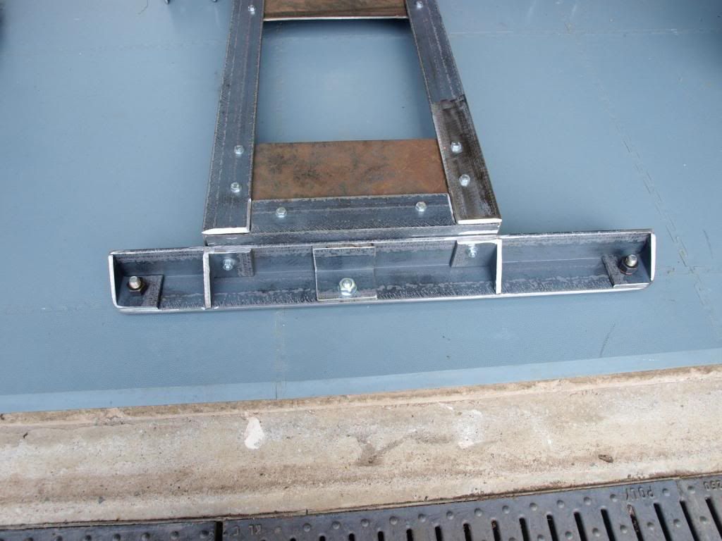
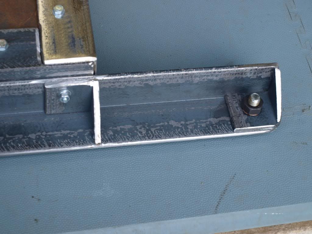
(17). Front Support: This photograph shows the underside of the front support section of the frame where the adjustable feed are fitted. The next two photographs show the detail of this part.

FrontUnderside_zpsad16242d.jpg


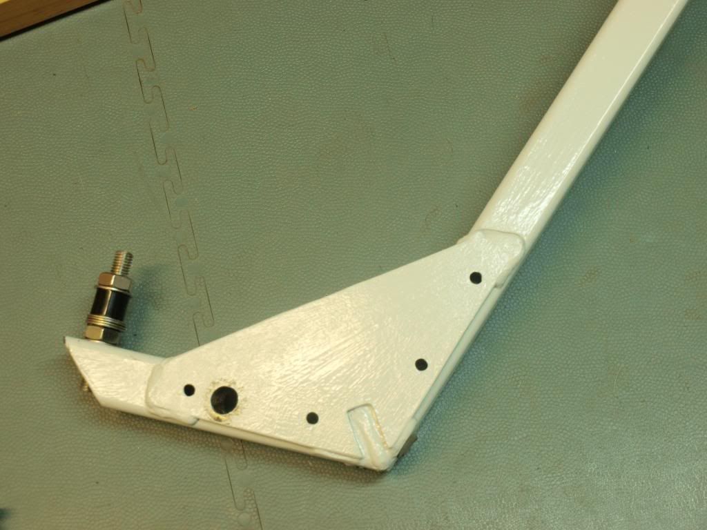
(18). At the extreme right hand side of the frame there is a triangular section fitted to give some strength at the foot mounting. A 10mm hole is also drilled through this and a bolt temporarily holds the two parts together. A 10mm UNPLATED nut has been fitted here and the nut will be tack welded to the frame to provide a fixing for the adjustable foot to screw into. On the left hand side of this photograph is another triangular section used to strengthen the section where it attaches to the frame. A 6mm bolt hold this onto the front "L" section as well as the central section of the frame. Again, this bolt is removed once welded.

18FootMountLeftUnderside_zps27bc2095.jpg


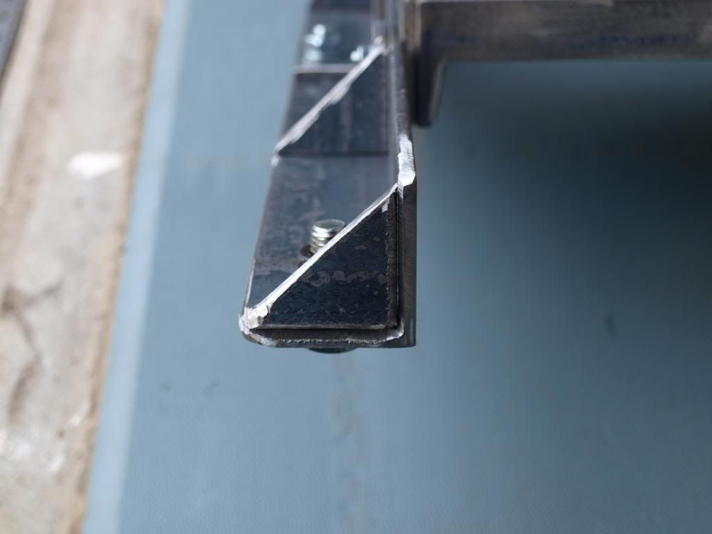
(19). The next photograph shows the end prep for welding, with a 30 degree chamfer added to each part. Repeat the whole process for the other side.

19FootmountLeftend_zpsc7cf612f.jpg


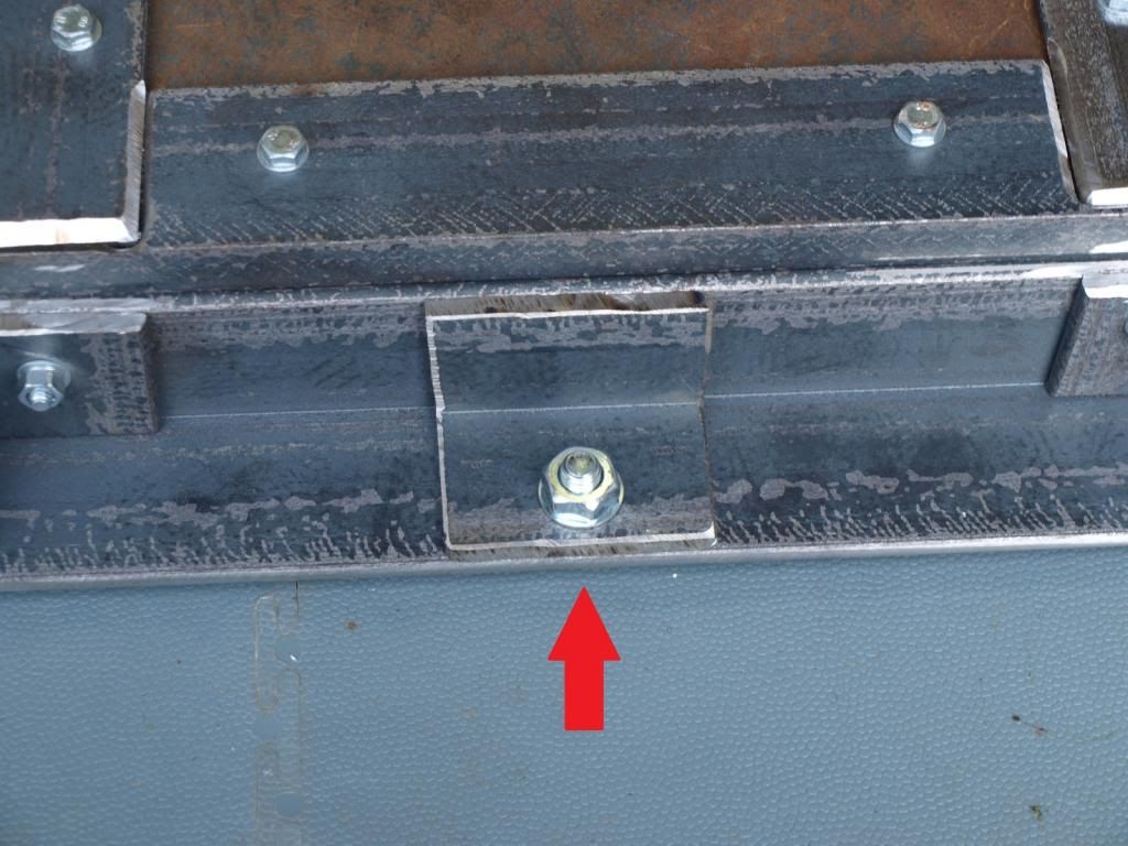
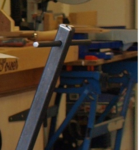
(20). The last part of the frame that you need to make is the lifting point in the middle at the front. I doubled up on thickness here and added another section underneath. This can be clamped to the main part and a 10mm hole drilled and temporarily bolted together for welding (see Red Arrow). When the bolt is removed, this becomes the hole for the lift bar to engage in - see next two photograph below.

20CentreLiftUnderside_zps89d02e85.jpg


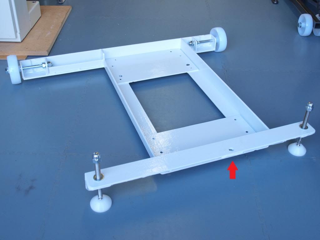
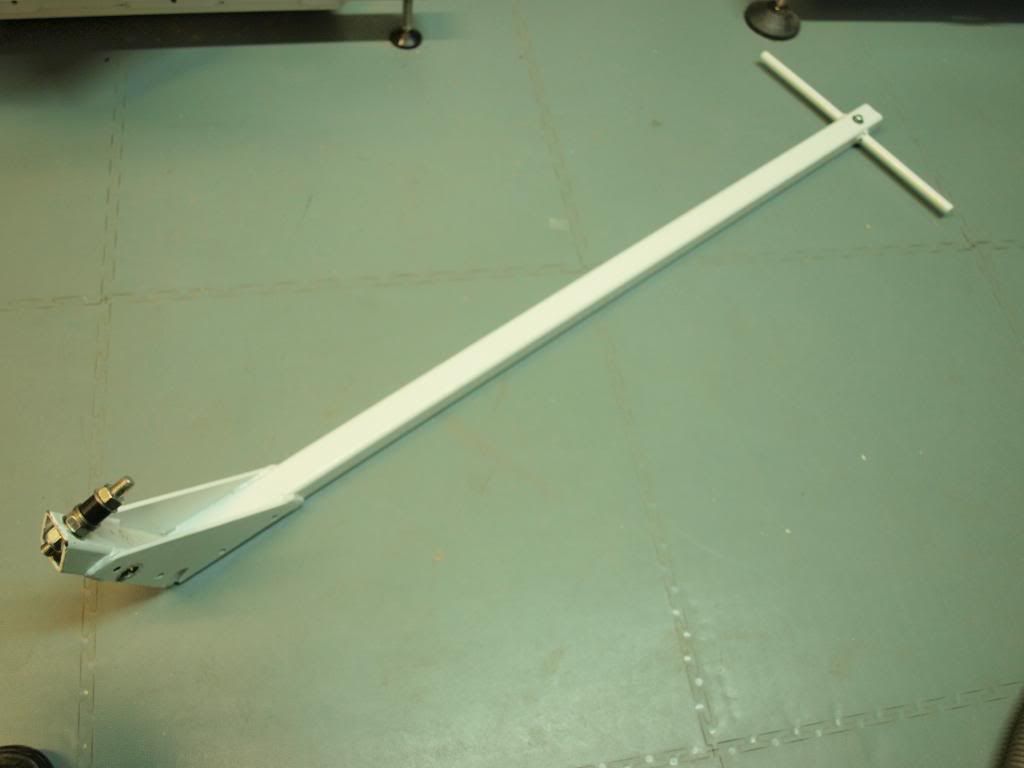
(21). And finished and painted after welding:

21baseliftpoint_zps27340507.jpg


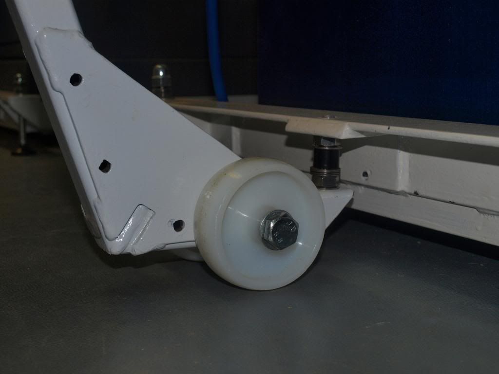
(22). You can now take the frame to your local fabricator for welding or do it yourself. Once welded, all the bolts are removed leaving only the two M10 nuts welded to the bottom of the frame (shown in photo 18). Now you can drill the mounting holes for the machine, In my case I had to drill four 12mm holes. Then I added a couple of coats of paint, fitted the wheels and axles along with two adjustable M10 feet (if you search the internet for suppliers you will get a number of companies who supply these sort of parts).

The machine can now be fitted to the base.

Almost finished, next instalment will cover making the lift bar.
 

Attachments

  • Centre Rear SF.jpg
    Centre Rear SF.jpg
    193.4 KB · Views: 25
@ndbrown - Nigel

Excellent post, very clearly written and photographed, and above all, very helpful. Thank you very much Sir - I bet these 2 pages took you longer than "a few minutes" to produce! Thanks for taking so much trouble.

Krgds
AES
 
Part 3 (Final Part) - Making the lift bar

I will start by saying that if I was to make this again, I would mount the axle lower on the bottom of the lift bar by extending the bracket down. I discovered on completion that my axle was a bit higher than it should have been, so I had to modify the pin that hooks under the stand to rectify this mistake. Having said that, it still works really well.

Materials - You will need:
Main lift bar = about 3m of 30mm box section mild steel with a 3mm wall thickness
"T2 Bar = about 400mm of solid black or bright mild steel bar between 8 and 12mm diameter
Brackets = a couple of pieces of 4mm mild steel plate to form the bracket at the bottom
Wheels = 80mm diameter Nylon with a 10mm bore (not the 100mm diameter ones used for the stand as these need to be low enough to go under the stand)
Axle = 200mm long M10 bolt plus 4 M10 washers and a Nyloc nut

All-in material cost for this was £15 and another £5 for welding

(23). I would start by cutting the main piece to length (cut it slightly oversize at this stage), sitting it over the axle and trying the geometry out with your stand (see photo below). You can bend the Box section really easily by cutting a "v" notch in the box section steel. You can also drill a hole at the top of the bar and fit the cross piece to form a "T".
The lift bar has absolutely no strength at this point, but it will have once welded with the brackets in place. See photo below

Withtrialliftbar-Copy_zpsa7220d3a.jpg


(24). To tidy up the top of the bar to avoid leaving a hole, remove the sides with the angle grinder and fold the back and front of the box section together as shown in the next photograph (apologies for the poor quality of this image). This can then be welded up and fettled smooth before painting. By this stage, you will probably start to get a better understanding of how it all fits together.

Withtrialliftbar_zpsfa73827c.jpg


(25). Make the triangular brackets up. Trial fit the whole assembly again to make sure you are happy with it and clamp and drill 6mm holes through the plate and the middle of the box section to bolt all of this together for welding. Once bolted up, you can position the axle under the stand and decide the optimum place for the axle to be placed.
Apologies, I did not have a photo before welding, so the one below below shows it after welding and the main axle hole has been drilled. You can also see where the 6mm bolts were fitted before welding. If you have your own welding set, you could tack it at this point instead of bolting it together.
NOTE: The notches cut in the bottom of the bracket are to allow access to weld the box section at the "v" notch joint.

24Handlebracket_zps19145a40.jpg


(26). This photograph shows the completed bar before wheels are fitted. You can now drill the axle hole in the bottom of the stand.

23Handle_zpsade12894.jpg


(27). This photograph shows a close up of the welding on the bottom inside of the bracket

25Handlebracketfront_zpsfac413cc.jpg


(28). This photograph shows the 80mm diameter Nylon wheels and axle (Bolt) before fitting

HandleWheelsandaxles_zpsfdd736fd.jpg


(29). This photograph shows the Nylon wheels and axle fitted as well as the lift pin at the front. You can position the pin at the front that engages with the hole in the stand at this stage. I originally used some 10mm studding for this when the photo was taken, but have since replaced it with some partially threaded 10mm bar. The threaded stud worked fine as well though.

Handlebracket4_zpsdebd00a0.jpg


(30). This photograph shows the lift bar fitted under the stand and ready to lift the mobile base.

22aHandleWheels1_zps7eca49be.jpg


(31). This photograph shows the lift bar fitted under my Sedgwick. It works really well and my 12 year old son can easily move the 200kg Sedgwick Planer/Thicknesser using this arrangement.

01aFront_zps666d1873.jpg


Finished: Well that should be it unless I have missed something. I can now get back to my original post covering the Sedgwick rebuild. Hopefully this article will help you if you decide to make a similar base.
 
Nigel,
Great build information - couldn't have come across this at a better time since I need to build some bases for my machines, however because mine are on a suspended floor I have the added complication of having to make the wheels retractable so as to spread the load when stationary.
I think I have worked out how to do that bit :? however just looking at your designs has helped me immensely - thanks for posting!

btw - I am planning to use pallet rollers for wheels because they take higher loads, come with bearings and are not too expensive only £7.08 inc vat here -http://www.bil-castors-and-wheels.co.uk/bzh8260wnybj-p-373.html

Cheers
Ed
 
Back
Top