katellwood
Established Member
Following an entry I placed on this thread and now having a bit of enforced time on my hands
stair-advice-please-t118948-15.html
I would now like to go through the build of this flight of stairs
Firstly I would like to congratulate MikeG on his excellent build of his staircase and apologise in advance re the lack of pictures taken during the build.
This staircase and balustrade also acts as the support for the upper landing with the client wishing to maintain a view to some original leaded windows found in the property (which dates from the 18th century and was originally a pub/Inn) and which I have previously restored and framed in oak.
In addition beneath the main stairs is another flight which accesses the cellar and was extremely difficult to design owing to the limitations of the floor space area available
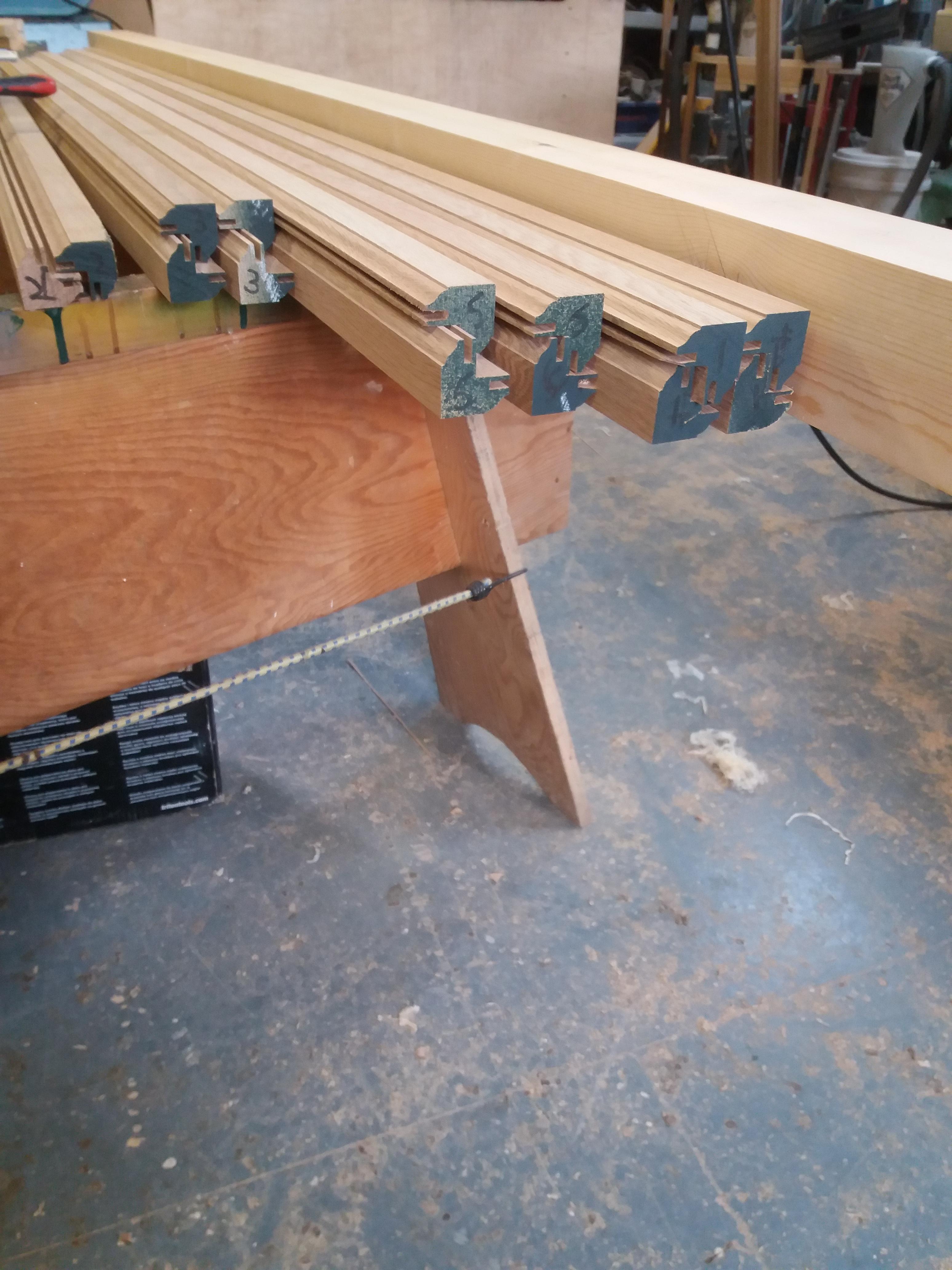
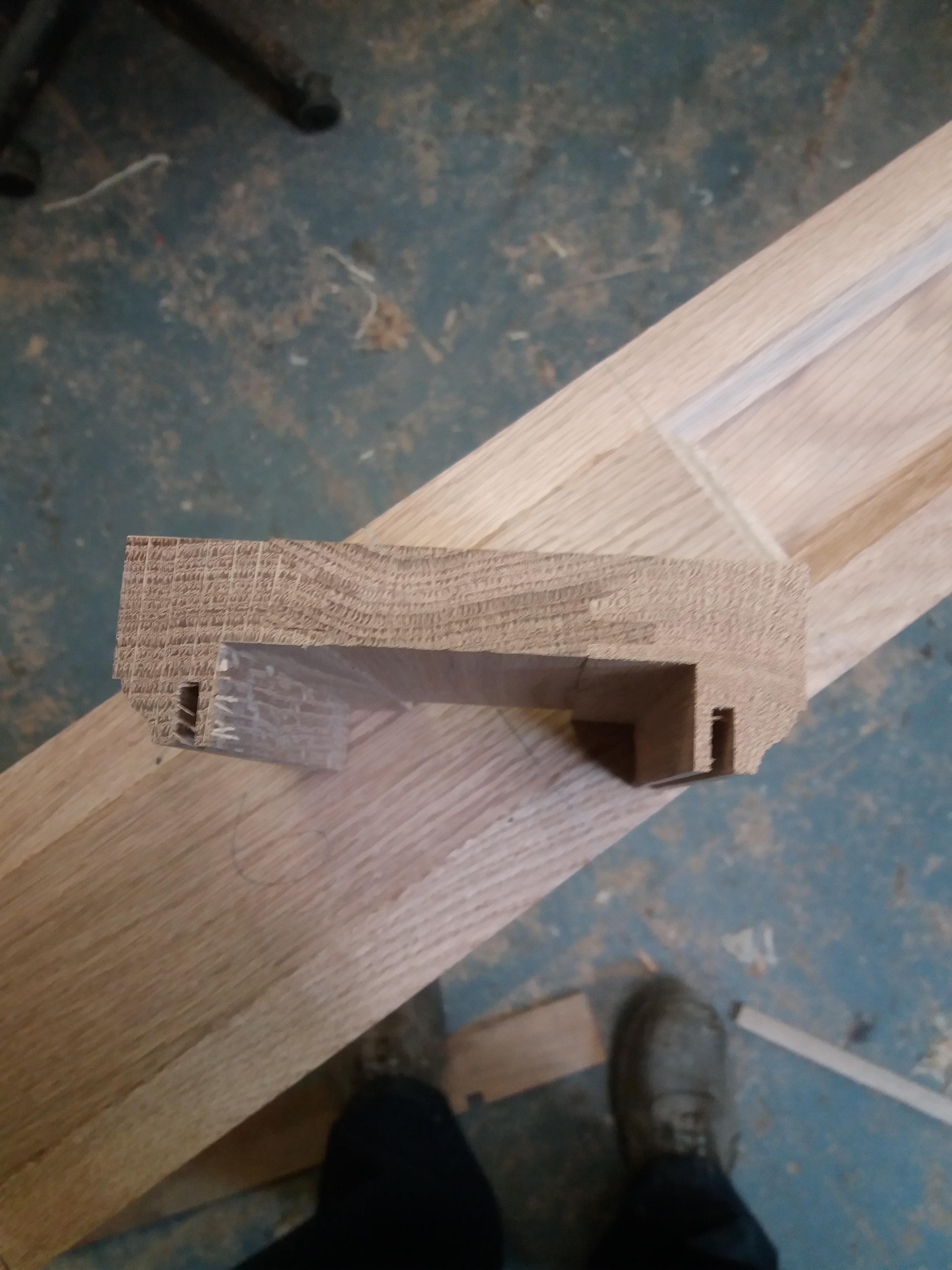
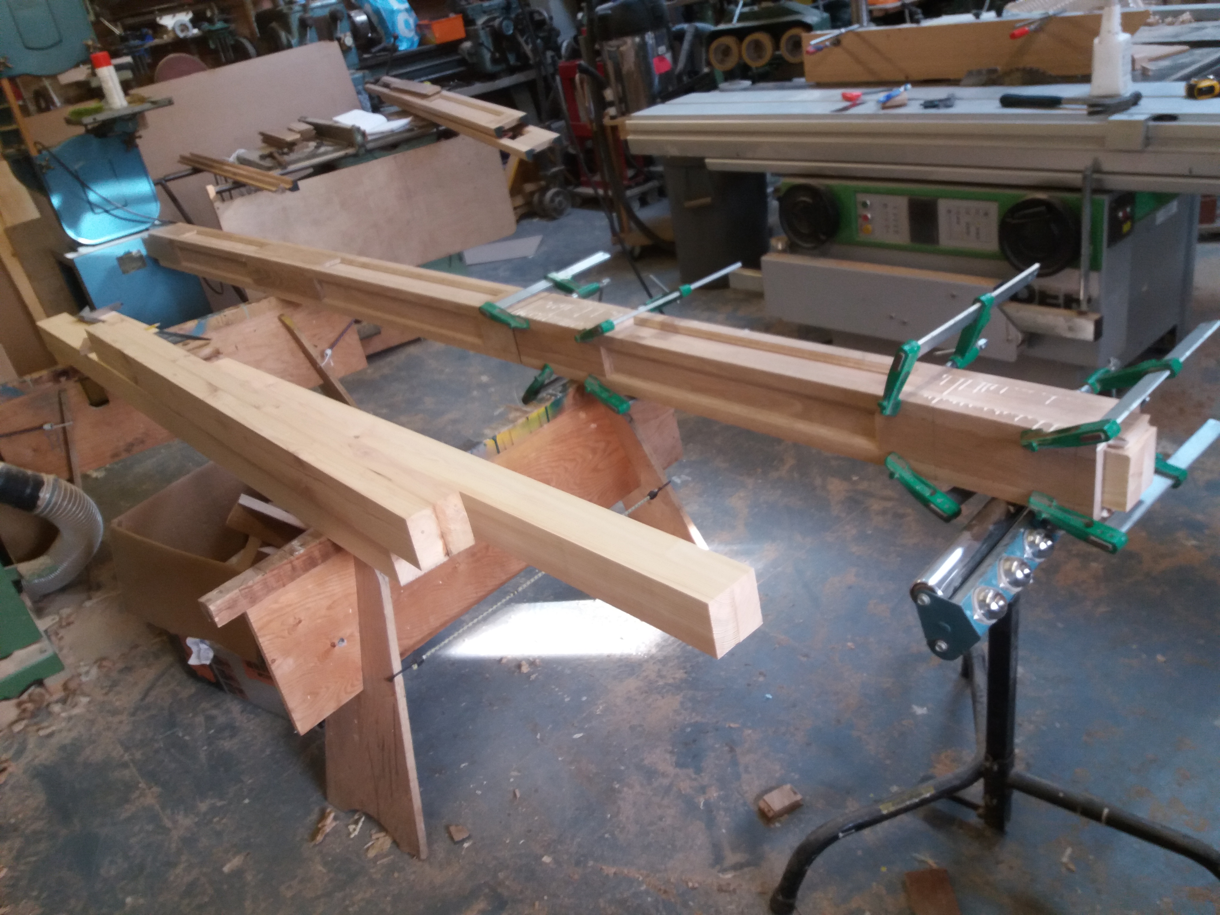
All the newels are constructed from 90mm square u/s softwood (made up of two pieces of 50mm glued back to back to prevent and movement. These were then clad in 20mm panelled oak creating 130mm square newels
Hope the pictures help in understanding this
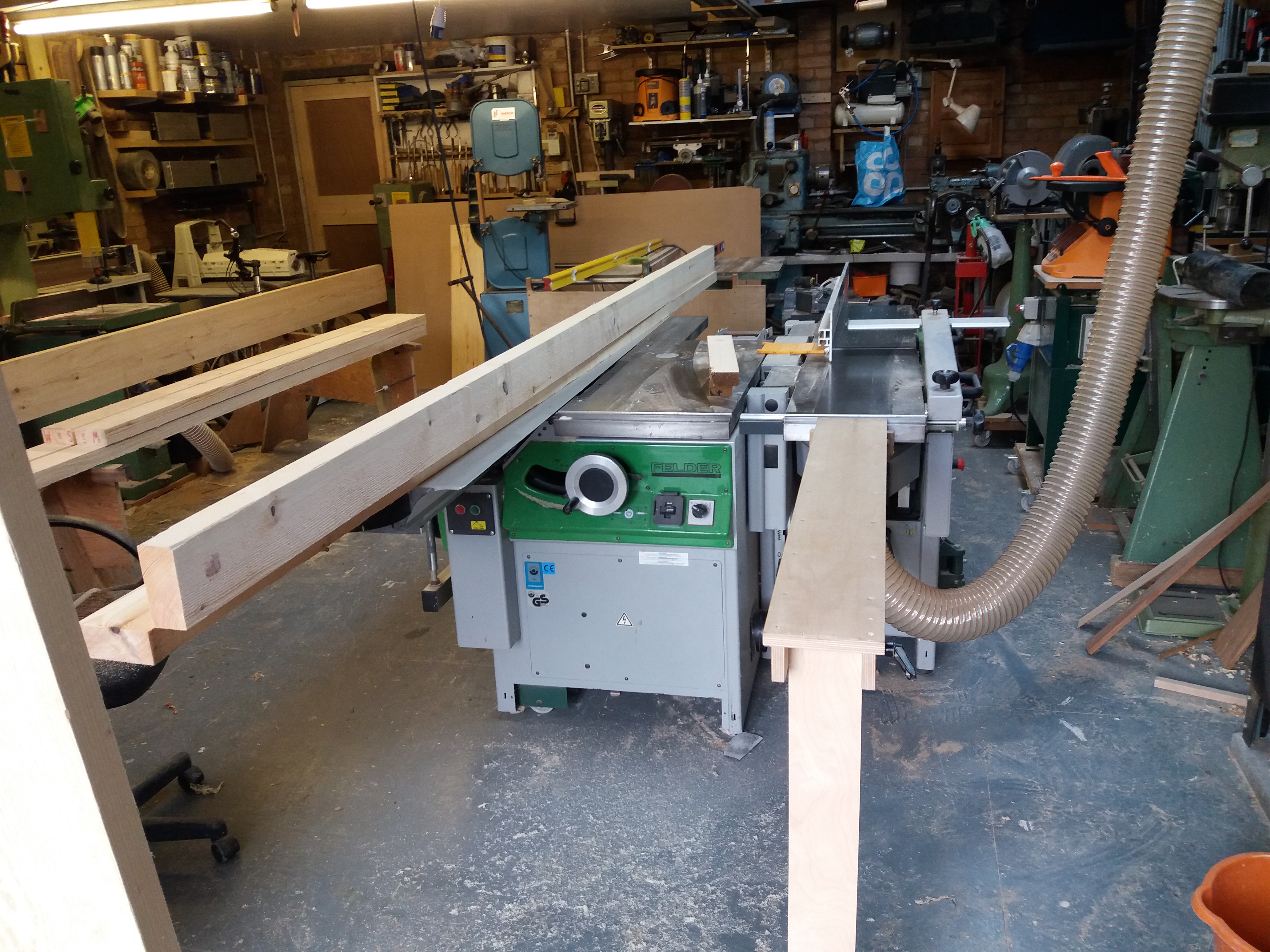
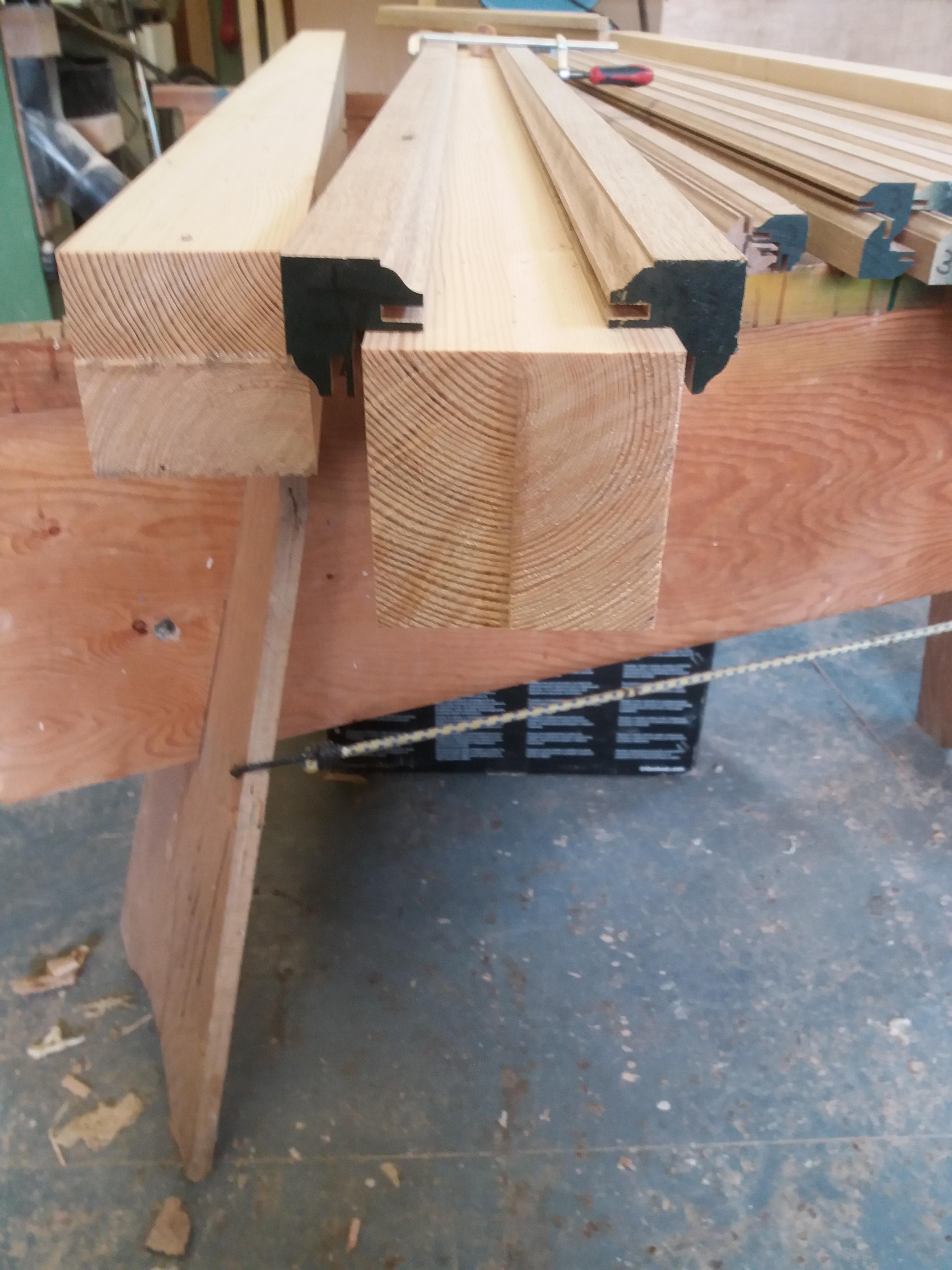
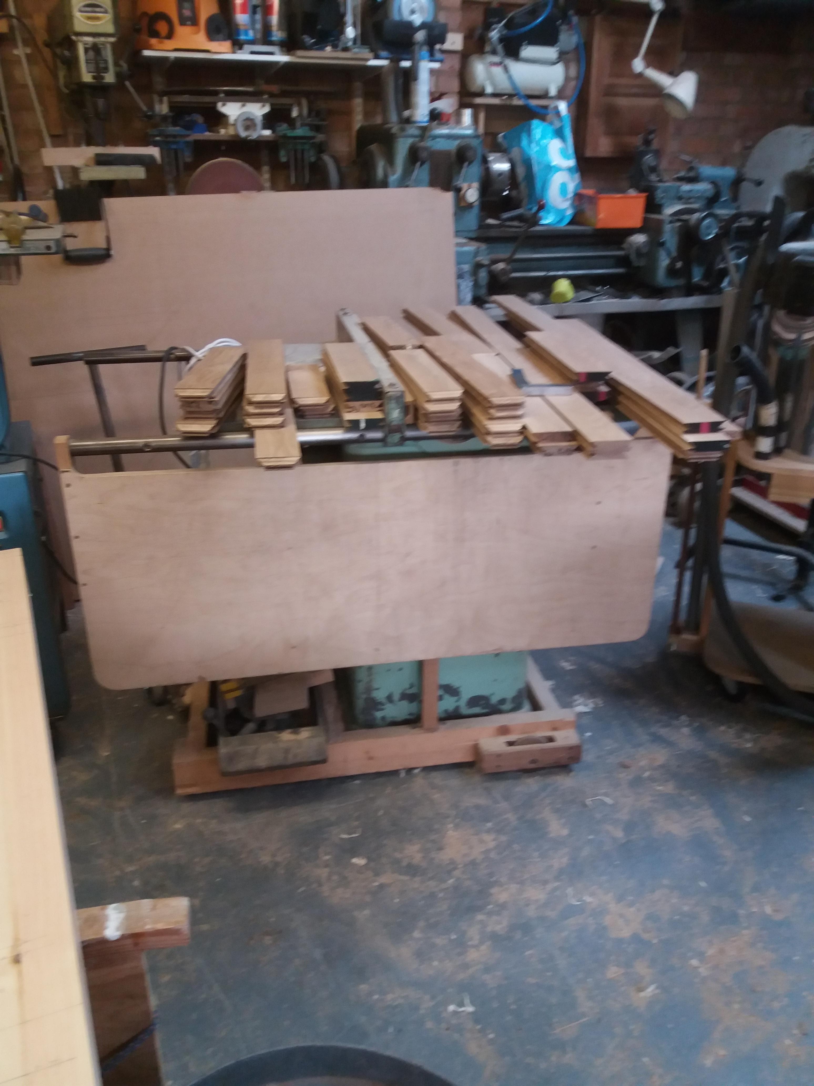
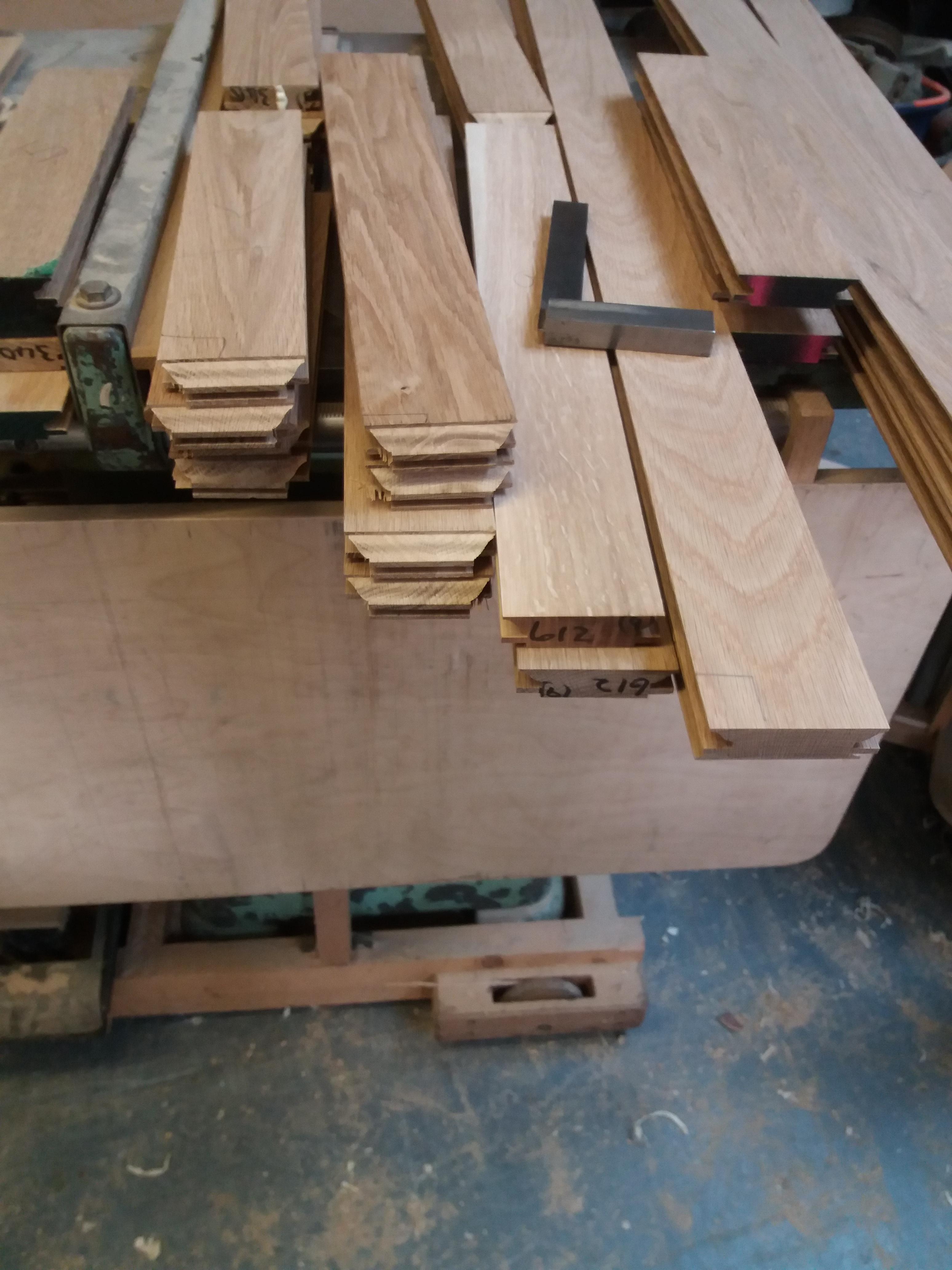
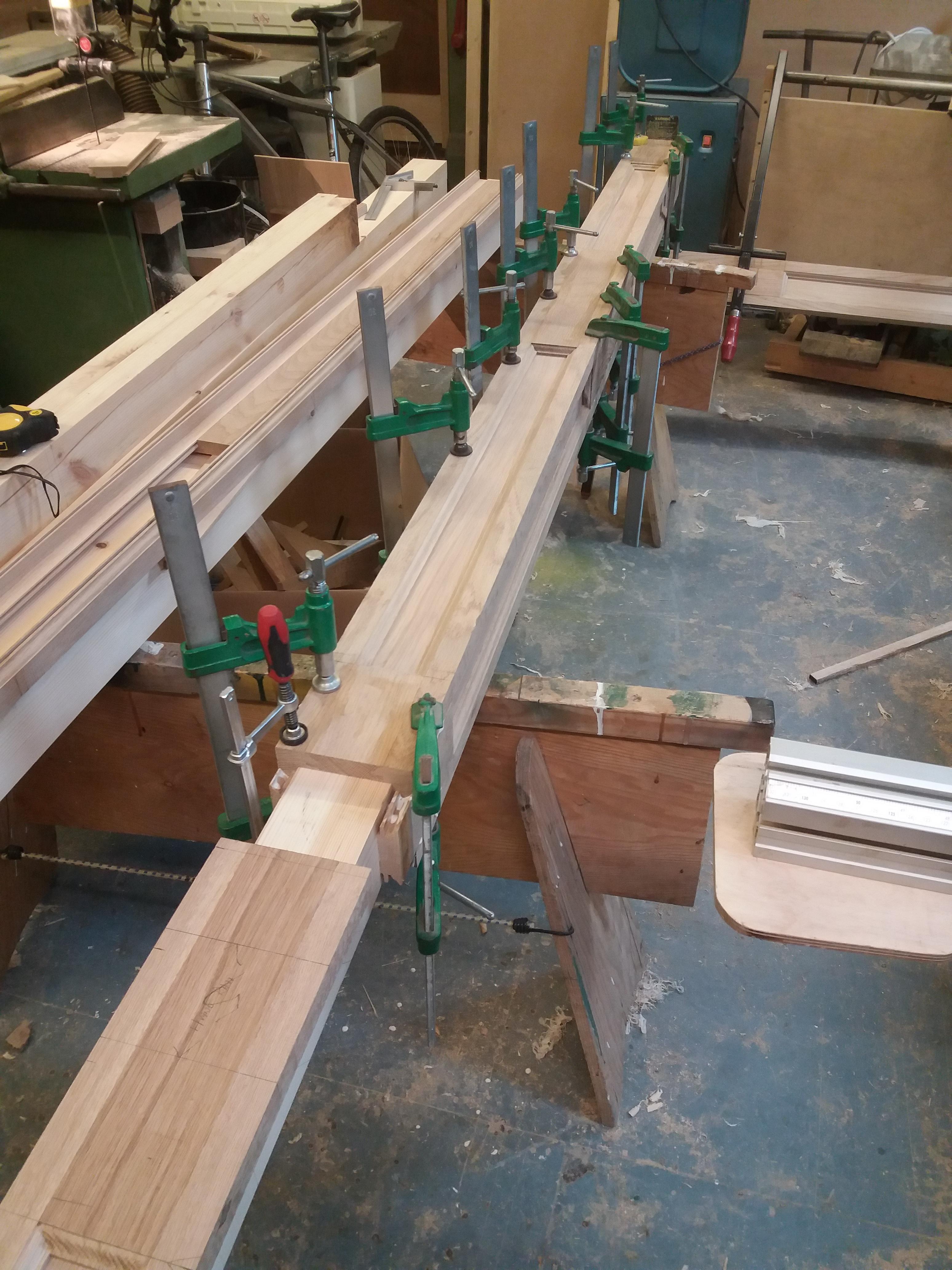
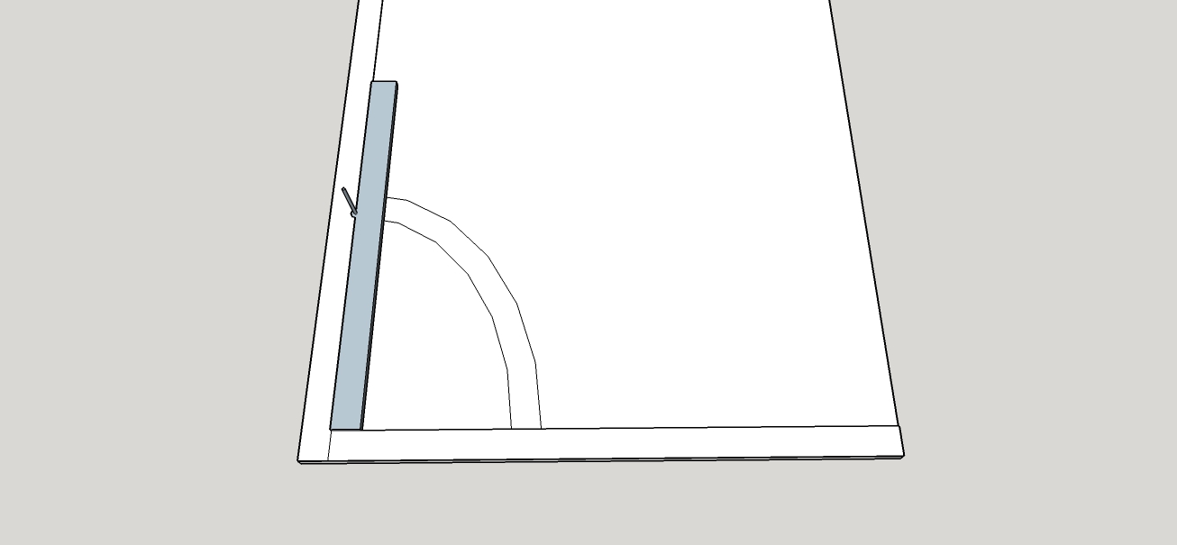
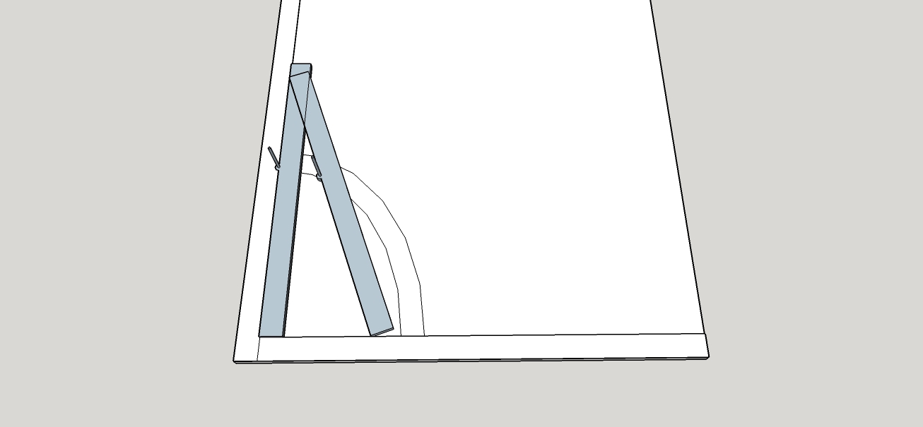
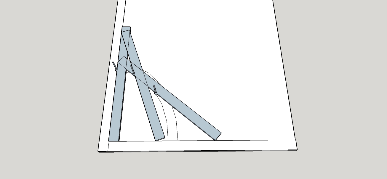
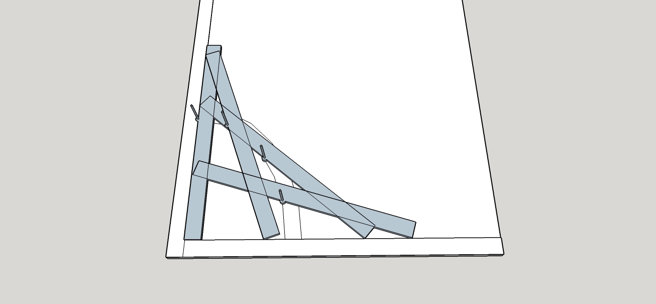
A full size rod in plan was created on an 8 x 4 sheet of mdf to locate all wall and wall corner locations and the radius in plan.
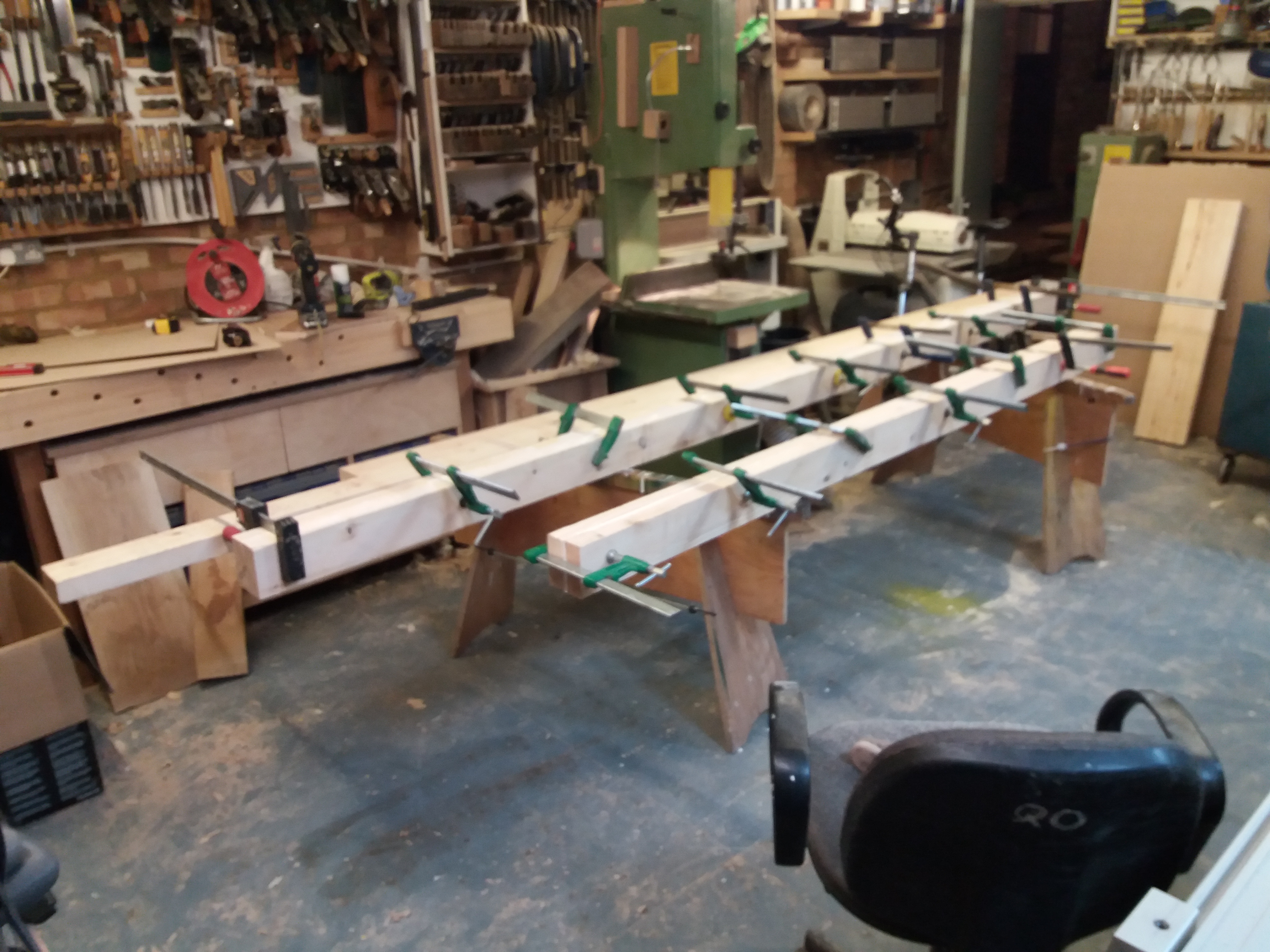
From the rod a jig was set out and built out of ply, 2x2’s and 3 layers 6mm mdf glued together and clamped with ratchet straps to facilitate making the curved string (sorry no photo’s of this however I still have the jig if anyone any pictures).
Upon making the jig it was then placed on the rod and riser lines of the cured section projected onto the jig followed by tread lines, in essence I turned the jig into a curved rod which included the top and bottom lines of the string.
As this setup was too big for my airbag and also the reason for three layers of 6mm mdf I covered to area of the string on the jig with clear packing tape then laminated 4mm birch ply to a thickness of 28mm. This was done in two stages with the first stage being glued on top of the second stage in an attempt to eliminate springback.
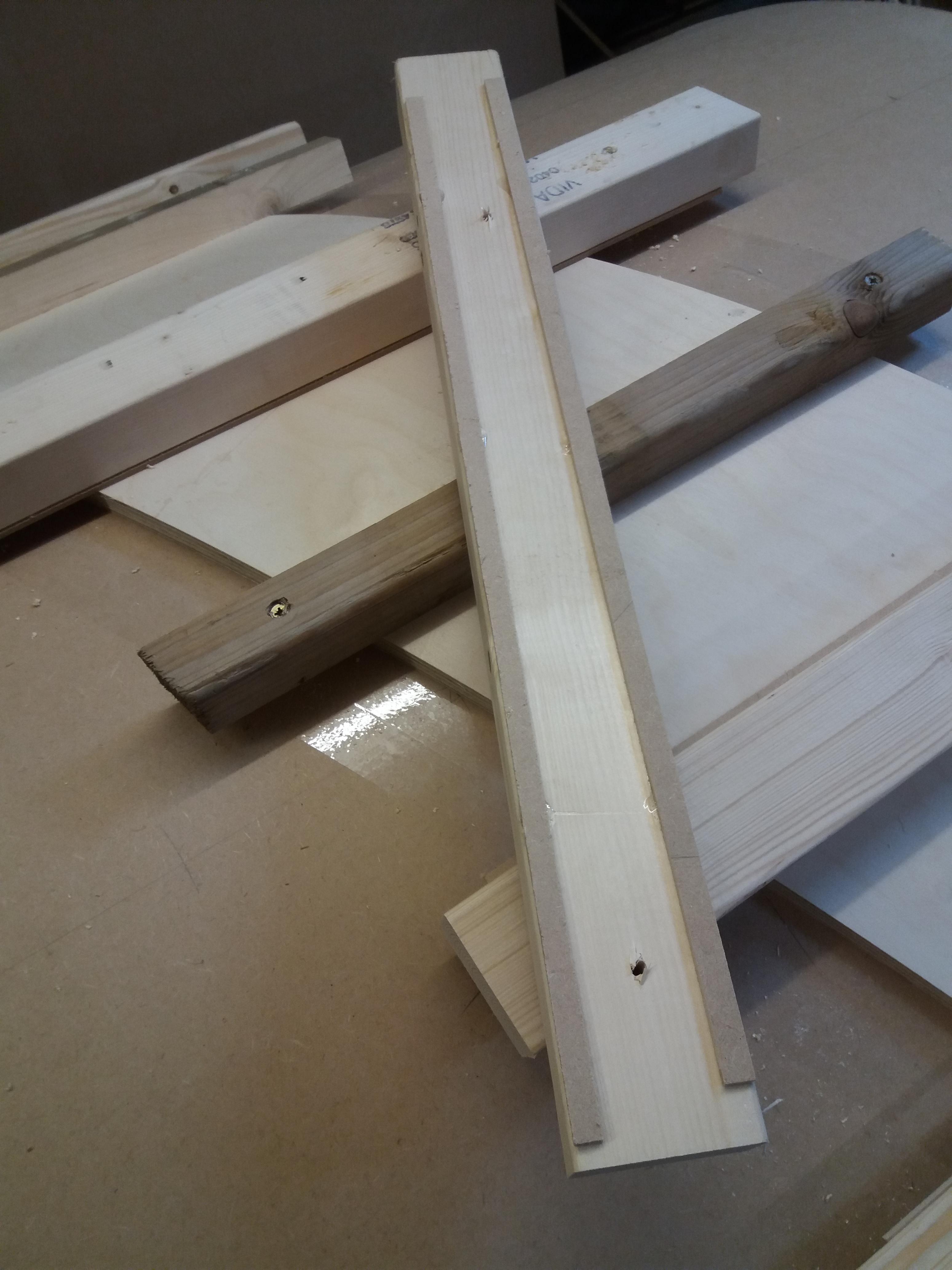
Lengths of materials/offcuts kicking around the workshop were utilised to clamp the ply to the jig, I also glued strips of hardboard with CA to these offcuts on the outer edges to spread the clamping effect.
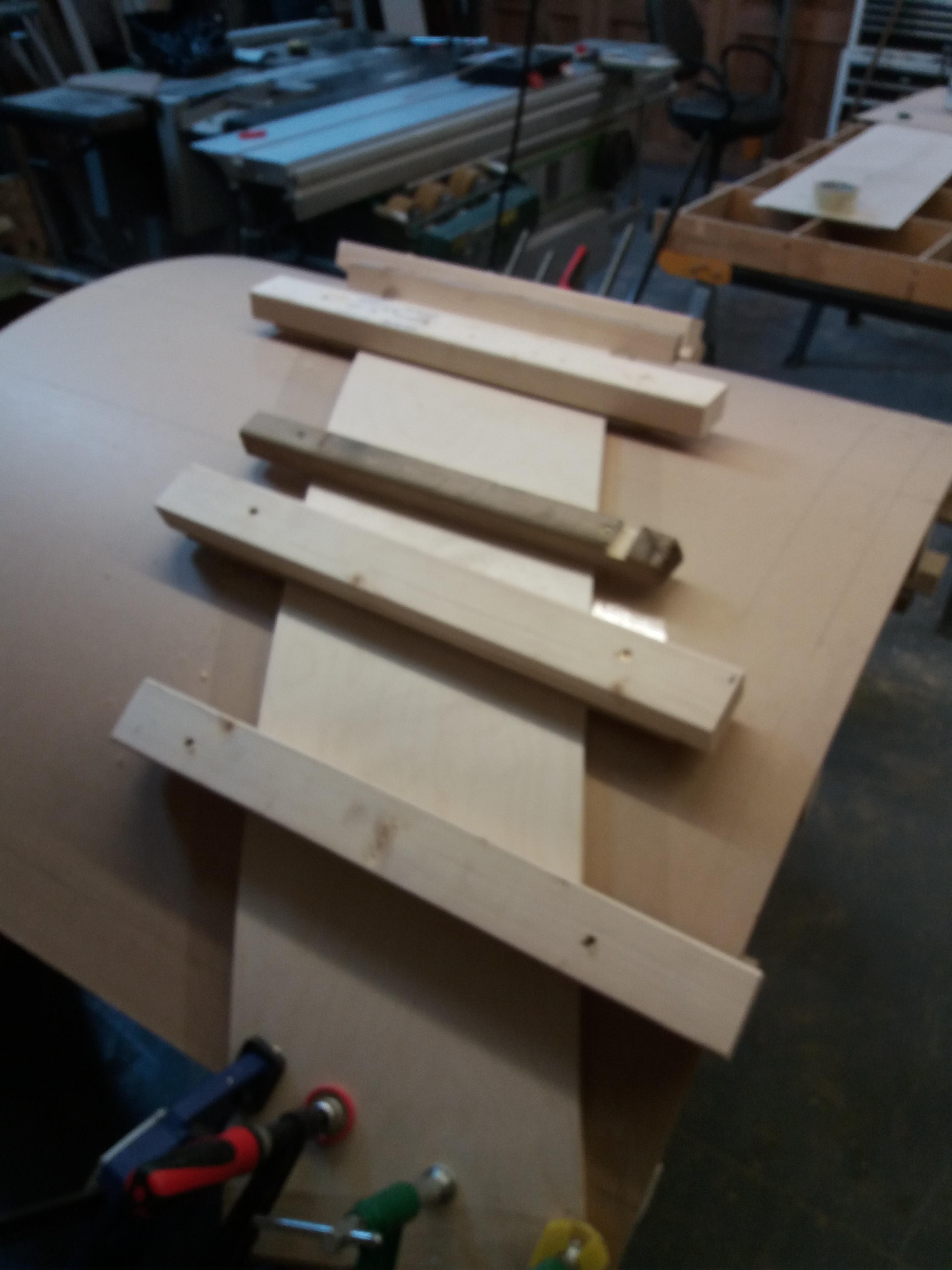
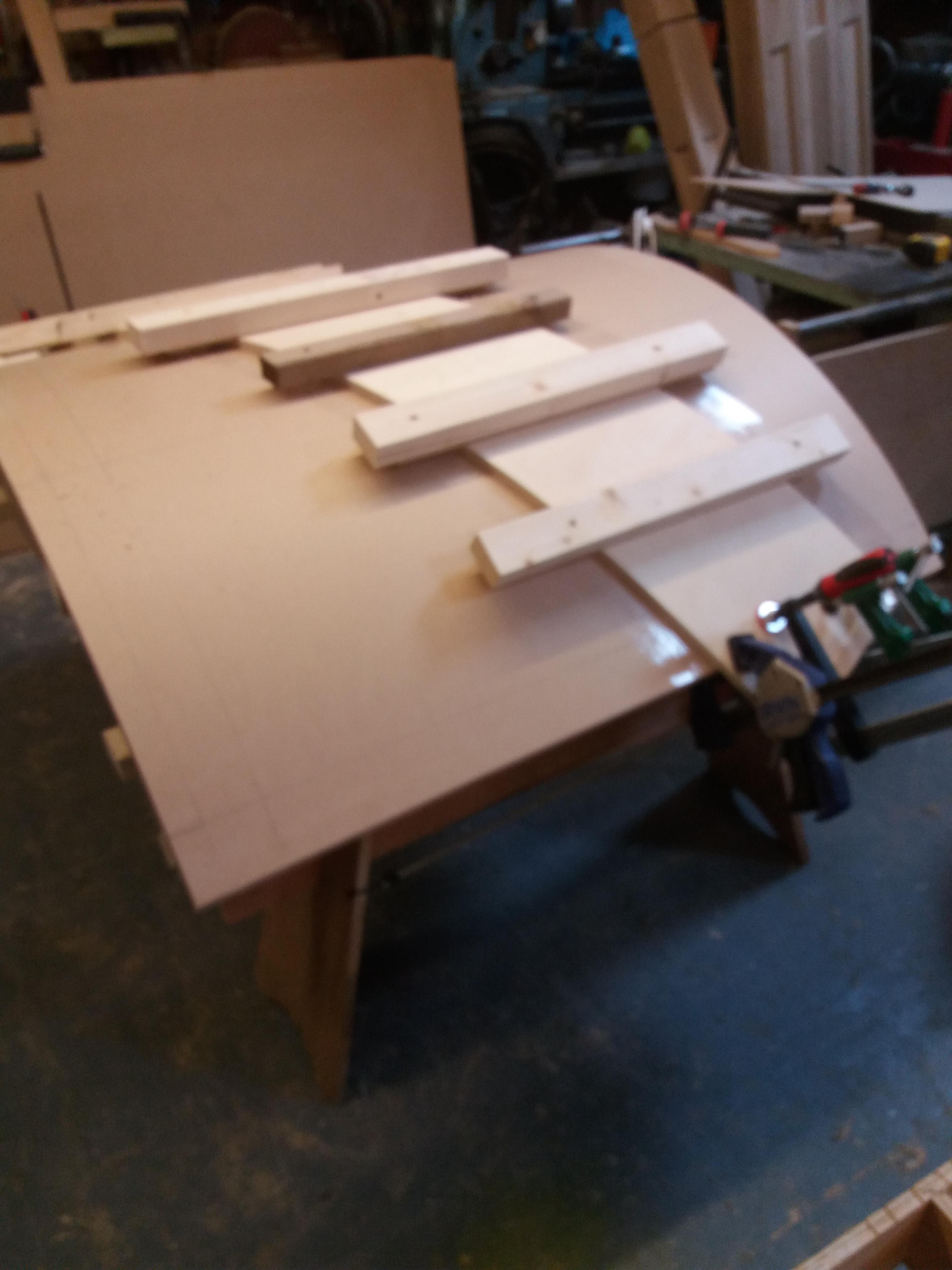
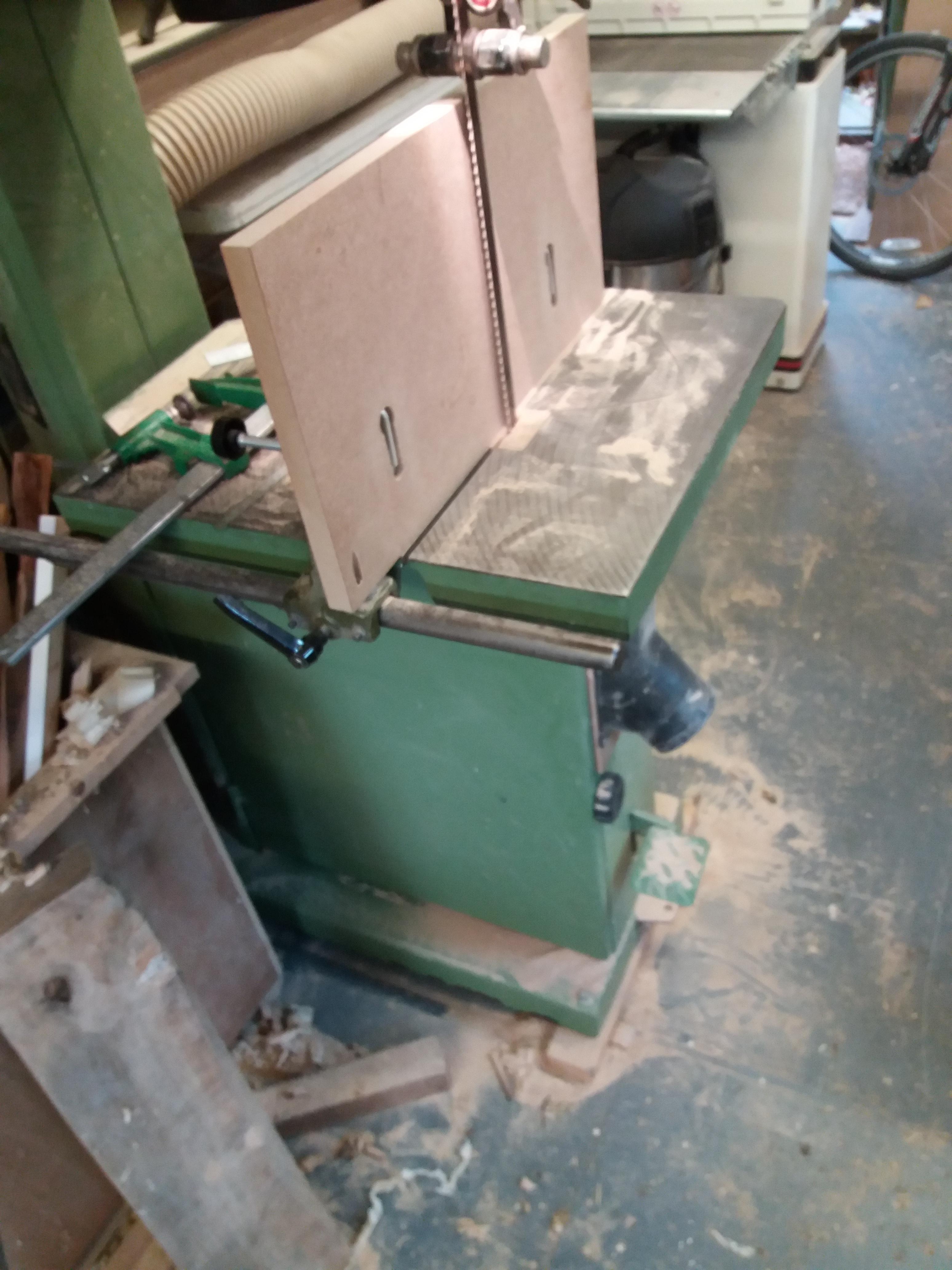
Once the ply had dried I resawed a piece of oak to 5mm on the bandsaw and ran it through the drum sander down to 4mm. This again was placed on the jig and all clamped up again
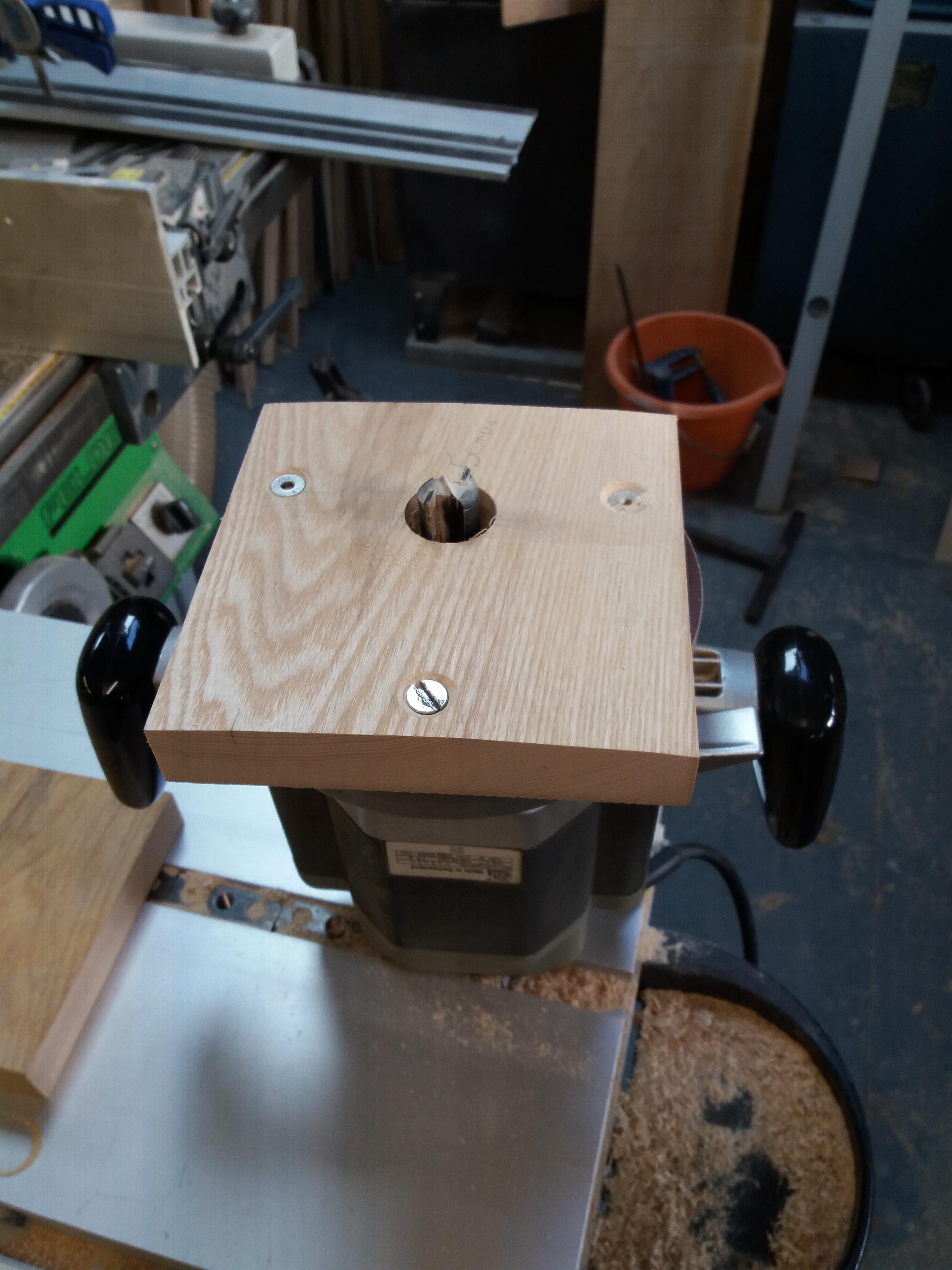
When everything was fully cured the jig was used as a setting out rod for the curved string and a reverse curved base was made for the router, the base had a straight edge at a right angle to the curve to allow it to run alongside of another straight edge
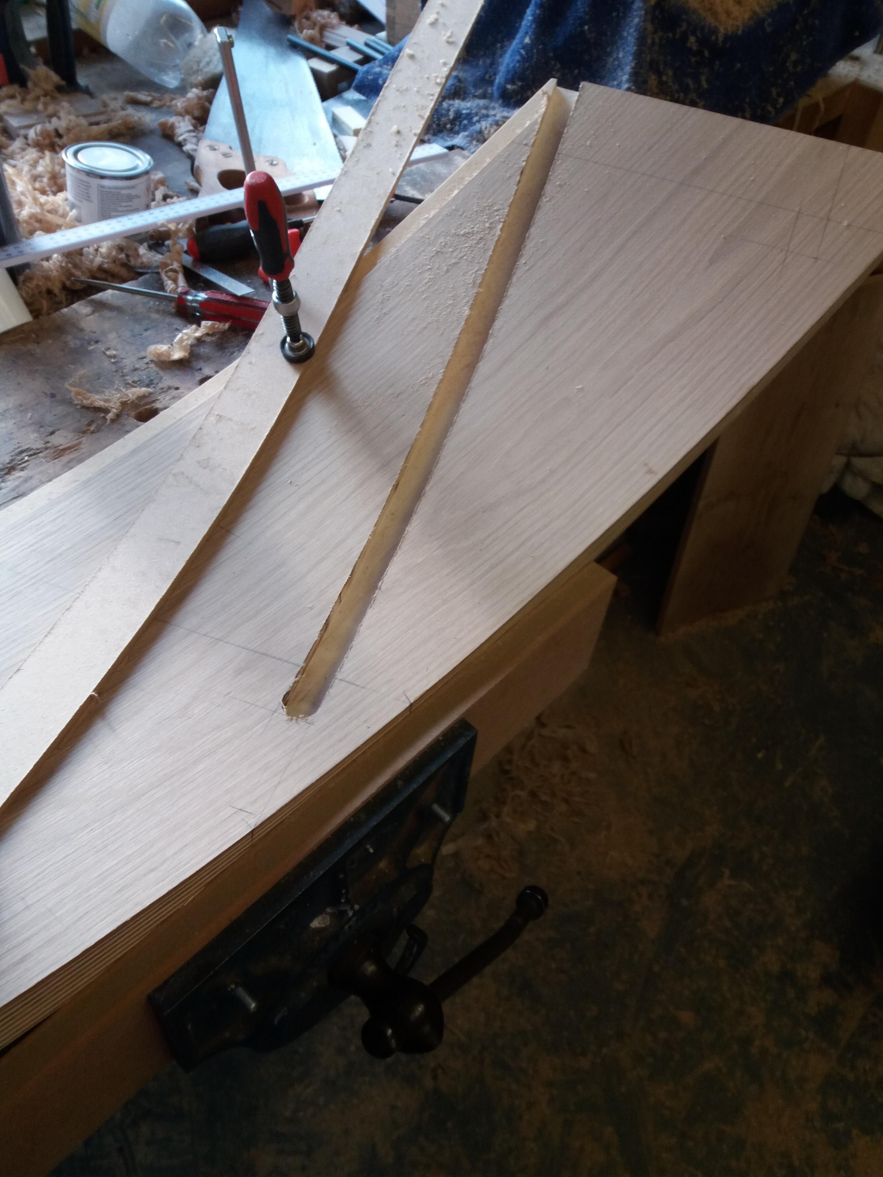
The riser housings were created in a similar way with underside wedge room also being routed (again a lack of pictures here). The housings in the upper newel were also routered and a dry fit was attempted. This is where working alone can be a right pain trying to balance/support everything to check all the joints.
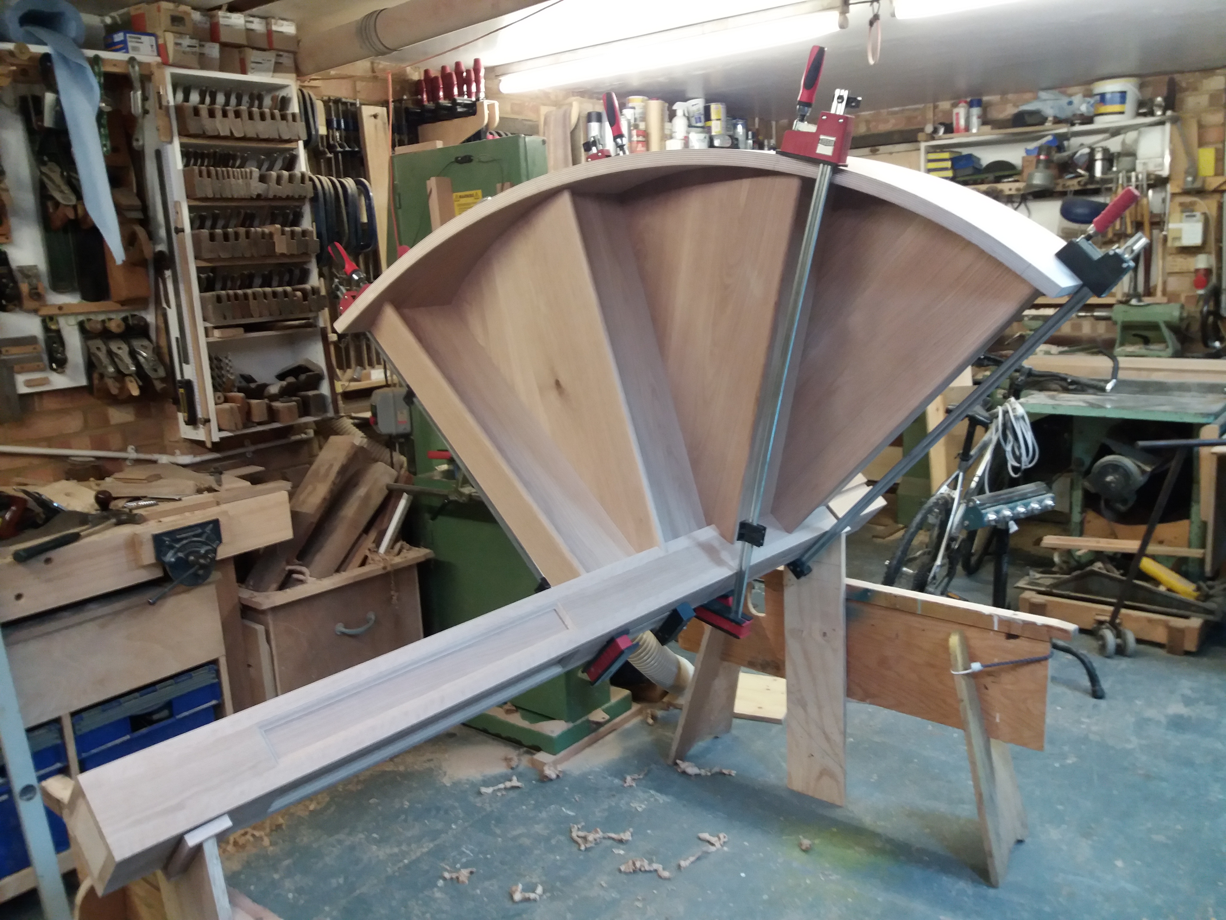
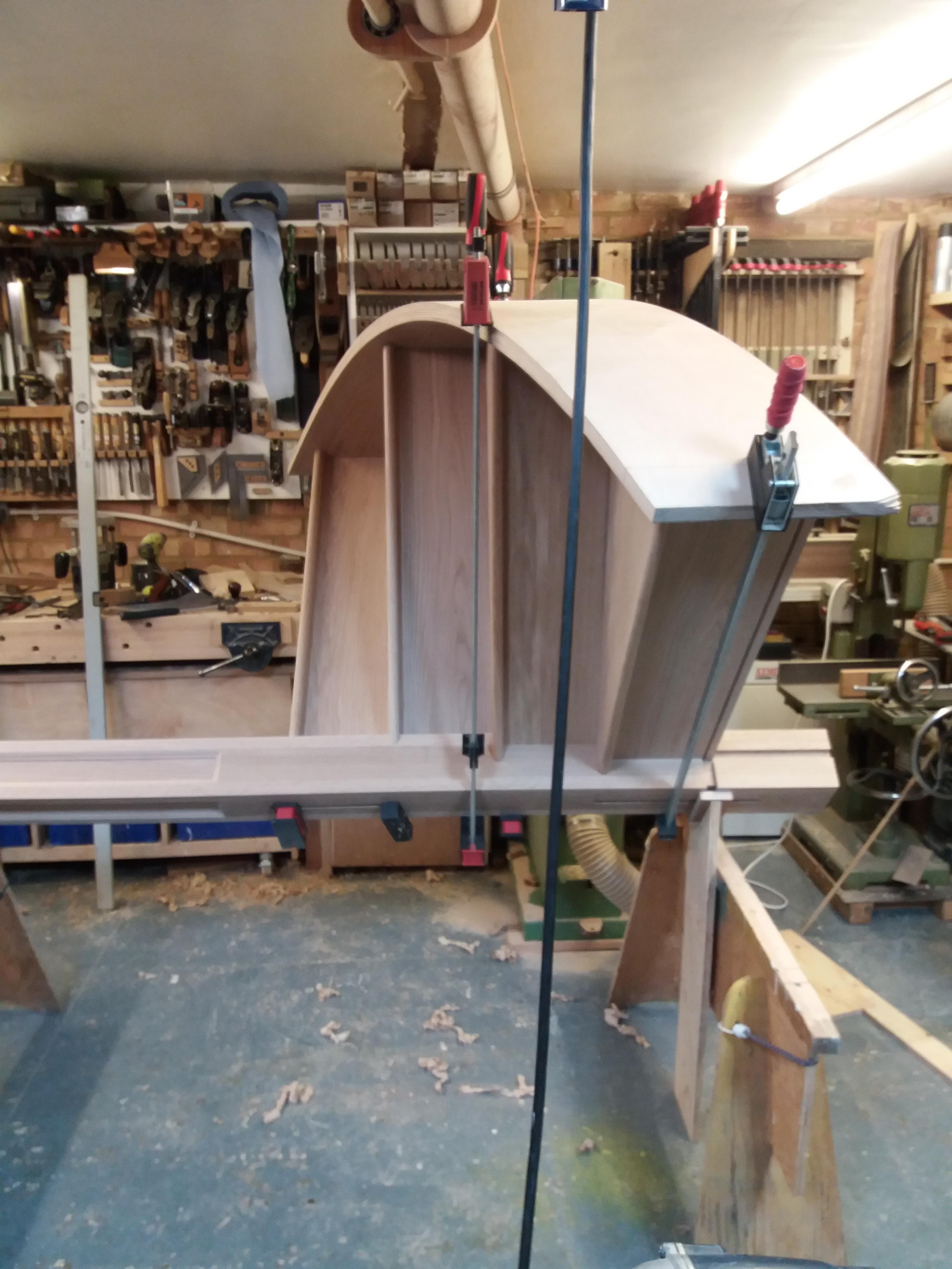
This whole upper curved section was glued and wedged, in addition I screwed the treads through the back of the curved string to keep everything tight. (both treads and risers are made from solid oak as opposed veneered mdf for the risers)
I then made a short section of two treads with closed strings which went against walls, this was attached to the curved string with a series of dominoes
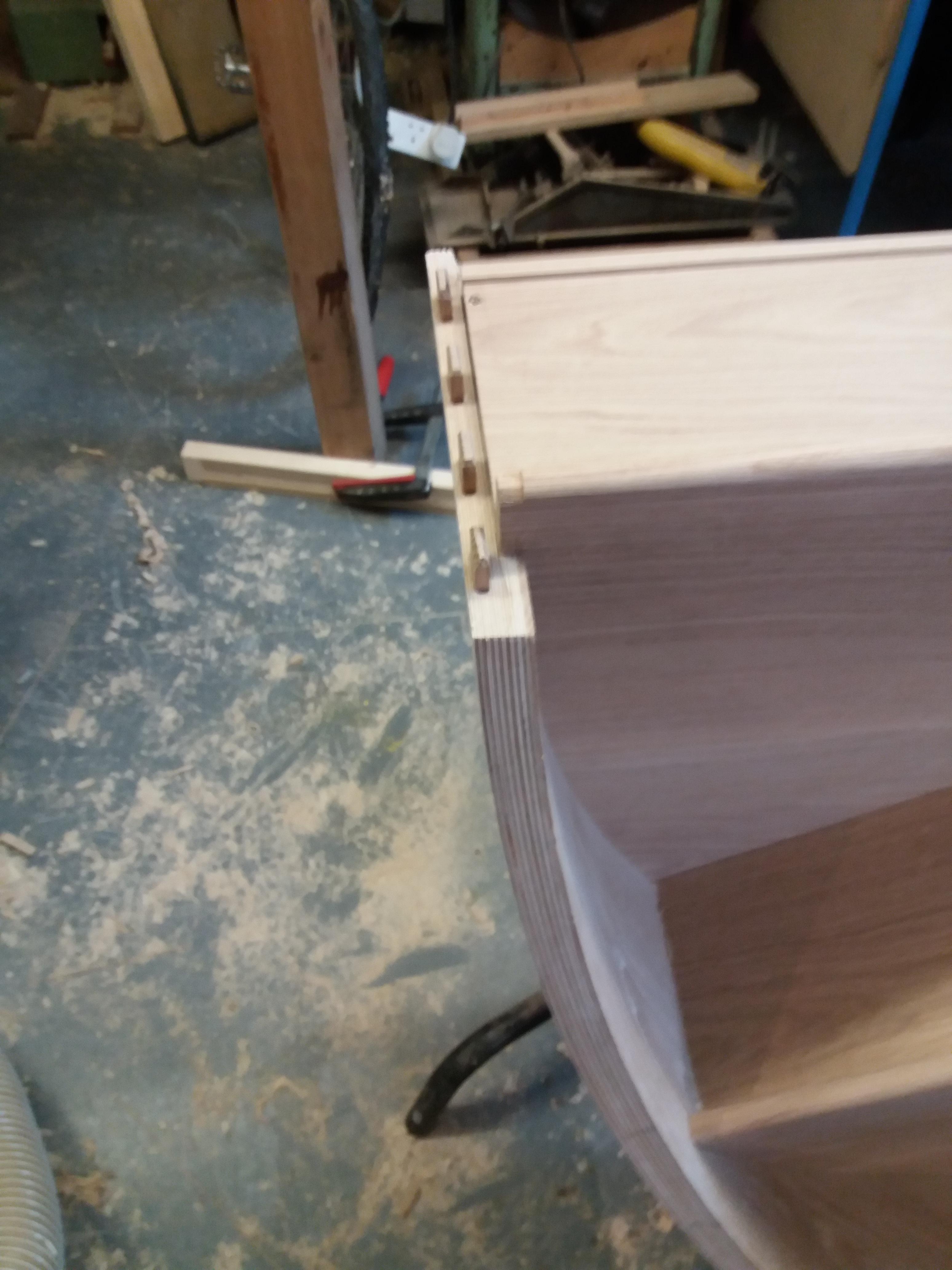
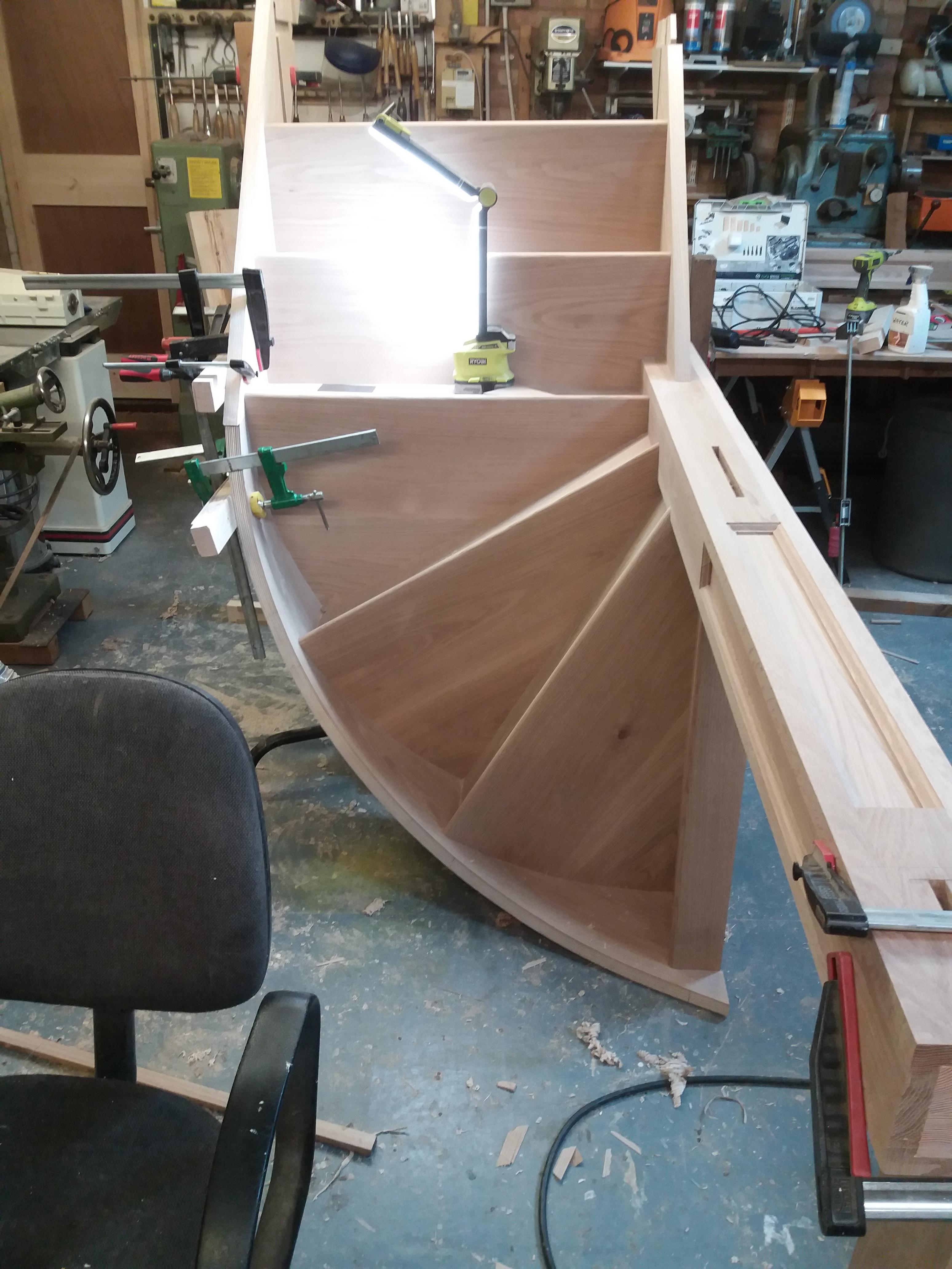
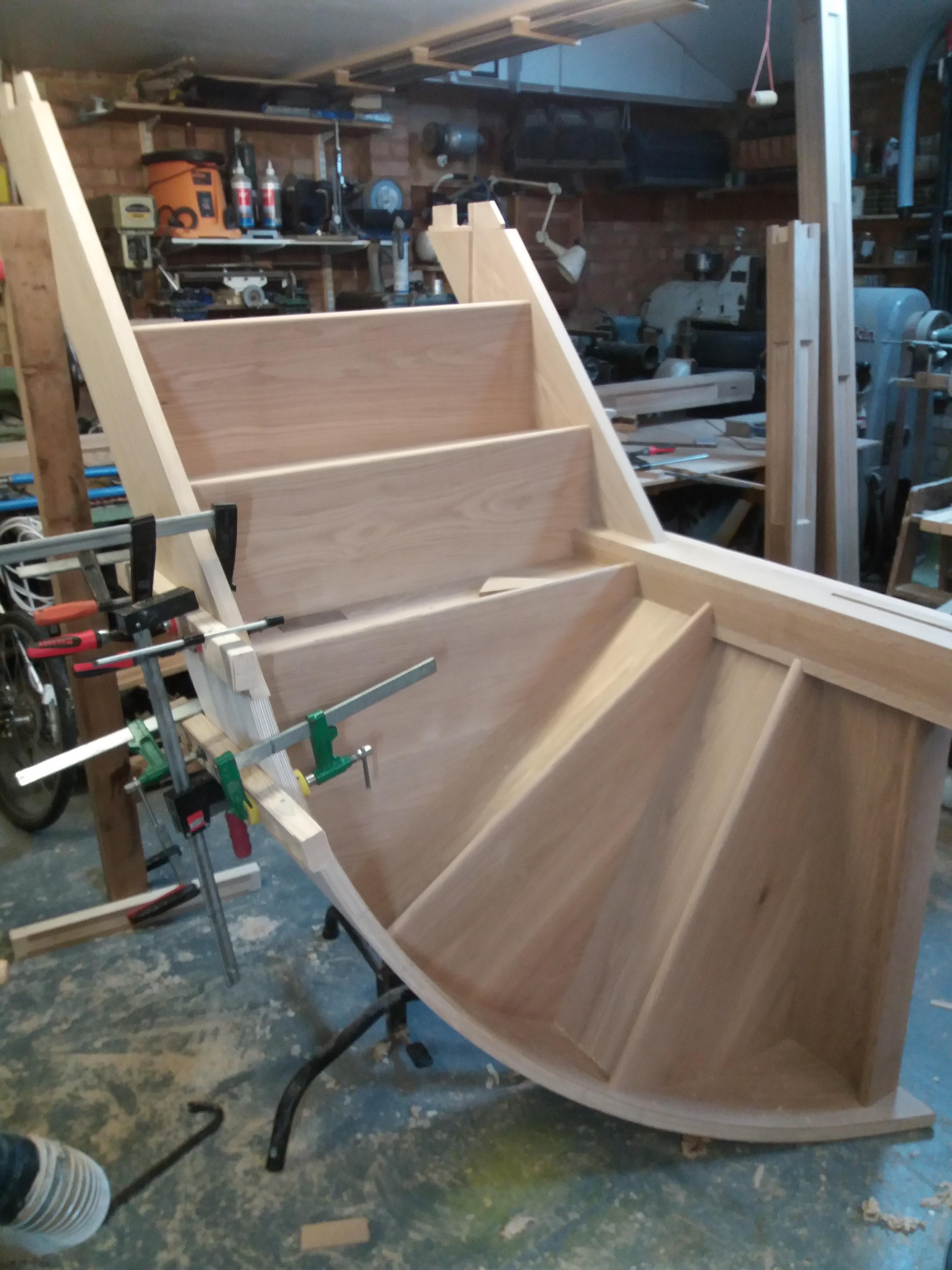
To further make this joint more secure I routered a couple of 30mm x 6mm deep grooves into the back of the curved and straight string and glued some appropriate strips into the groove to improve strength.
This assembled upper section was to be jointed into two newel posts half way up the full stair where it came into contact with walls (all will become evident as I proceed).
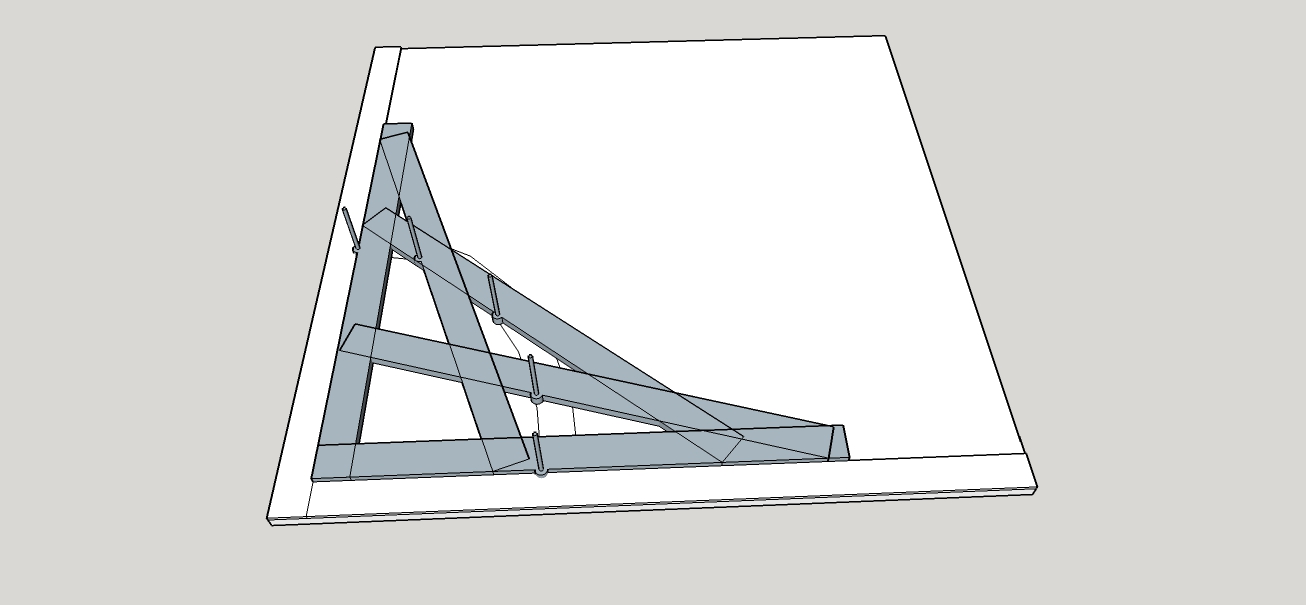
The next stage was the lower section which was to be cut or open string. I would have liked to have included brackets to the design as I think they enhance a stair plus they can hide a multitude of fixings however, on this job it was not to be however, I did incorporate mitred breadboard ends to all the lower treads. Again I did not photograph the construction of the cut string but have a sketchup of how the construction went
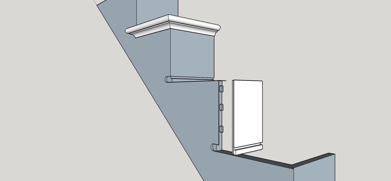
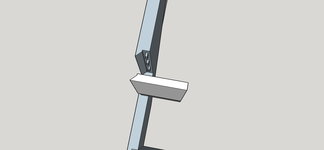
All joints were fitted and as much of this section was glued in the workshop to as larger sections as were practicable to facilitate transport and access. Scotia moulding was machined added to the underside of the treads.
NB, on a cut string to secure the riser a screw can be used behind the scotia and behind the tread prior to it being fitted
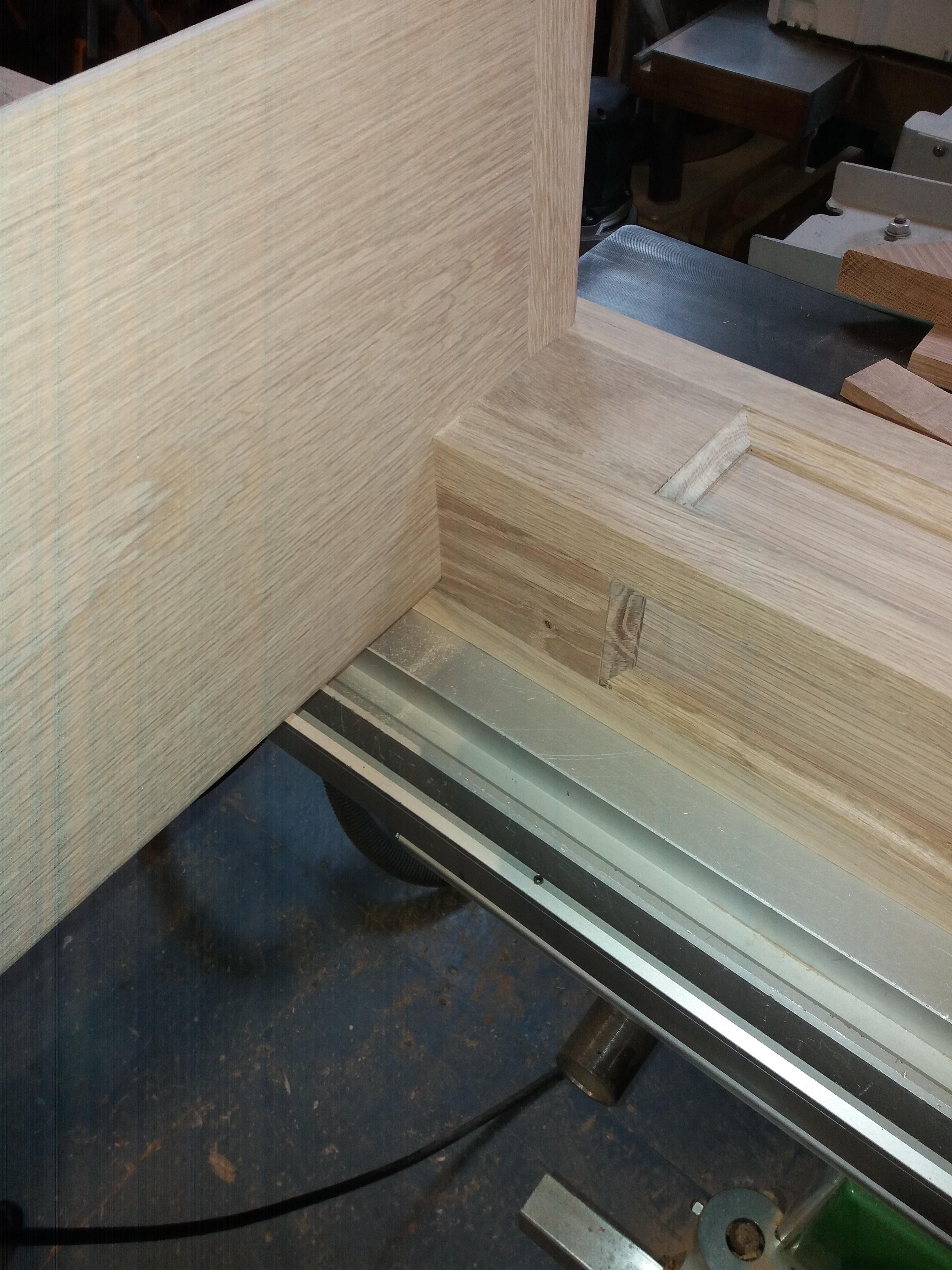
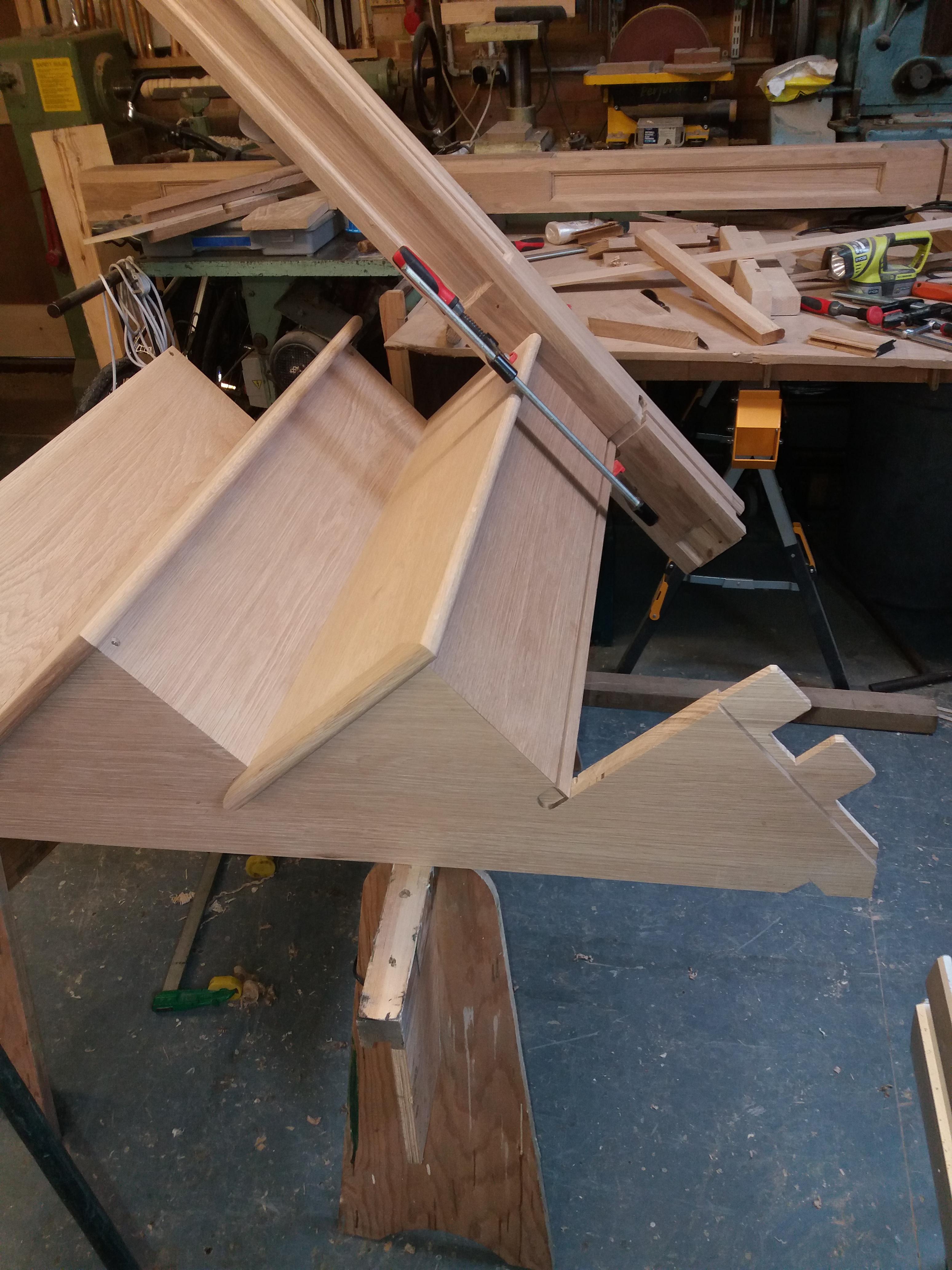
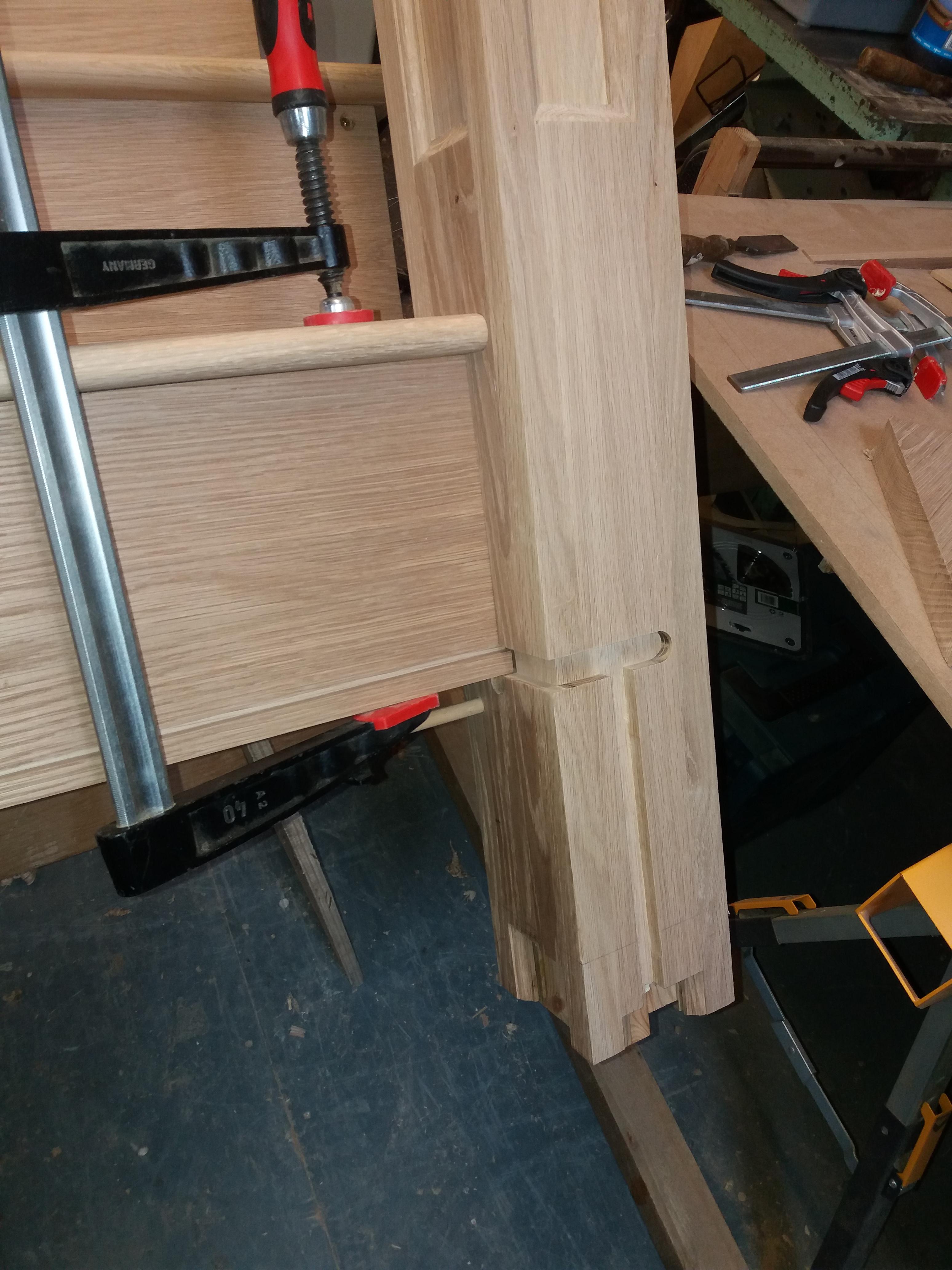
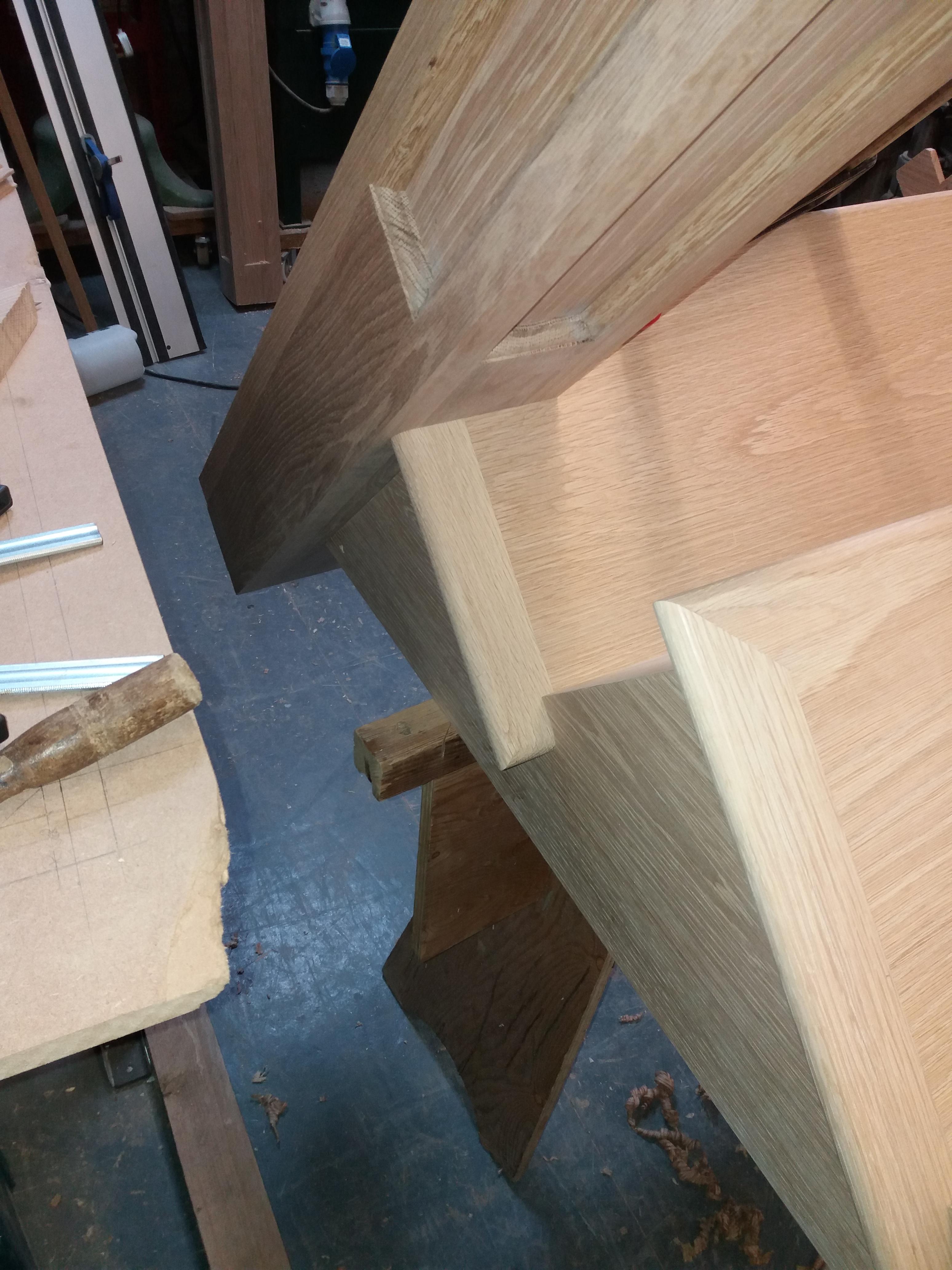
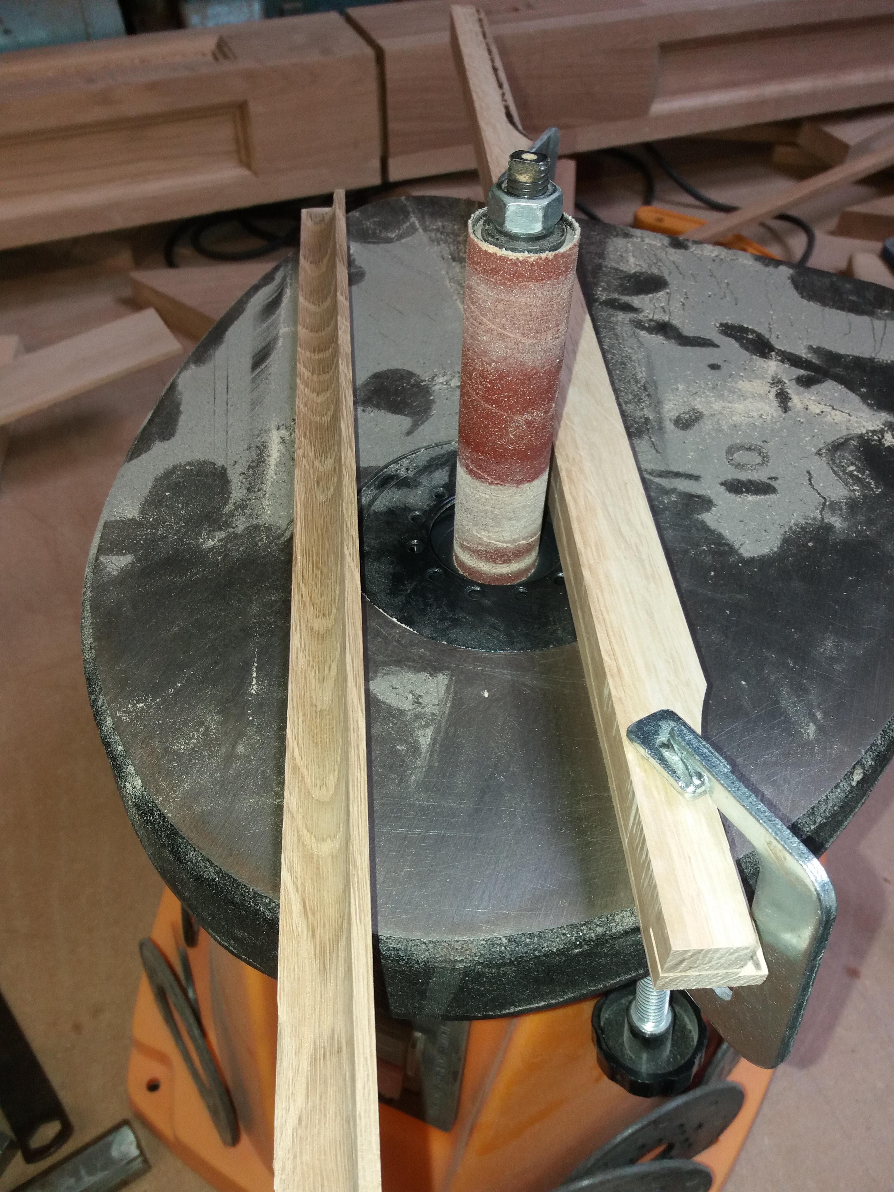
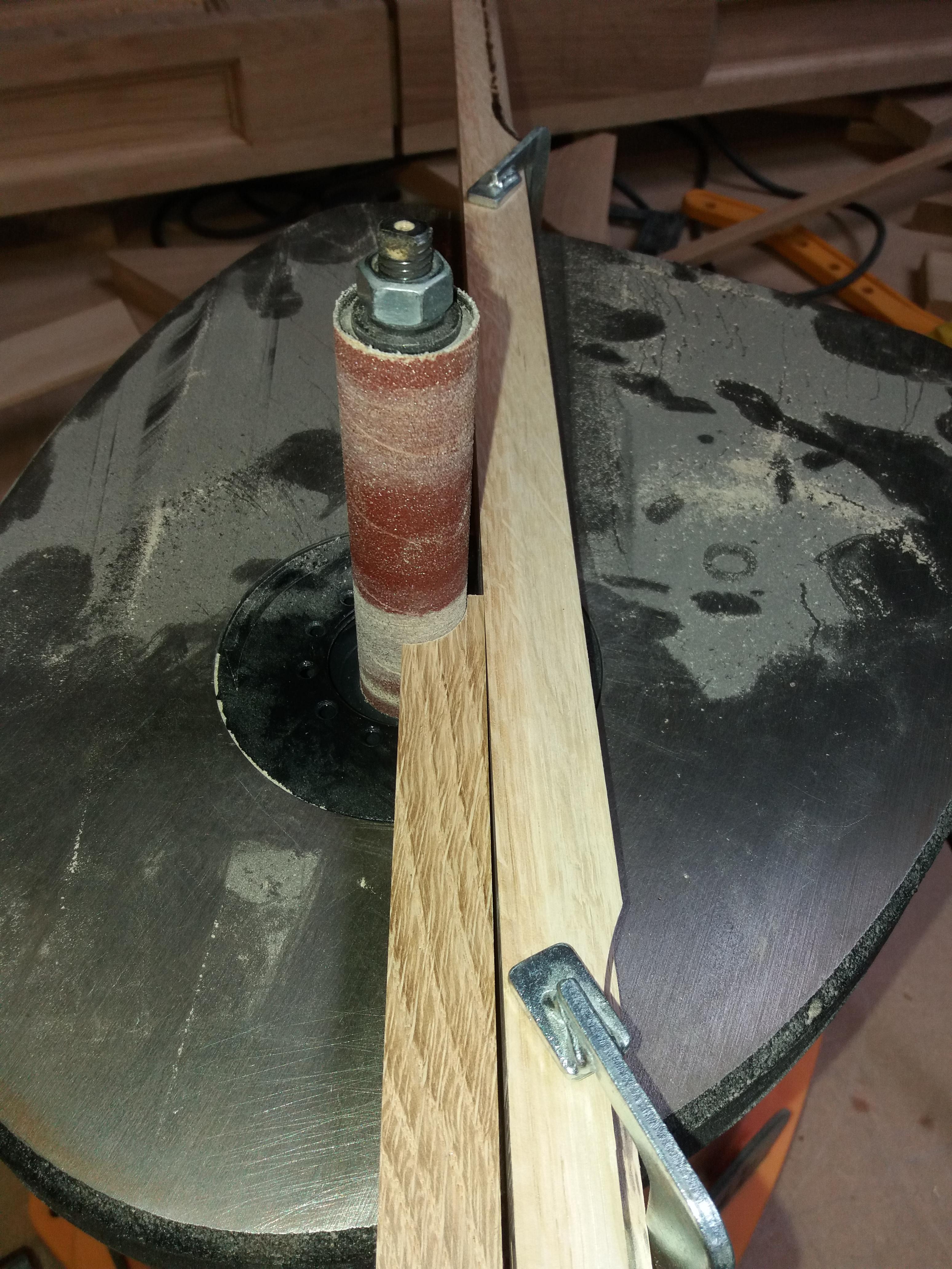
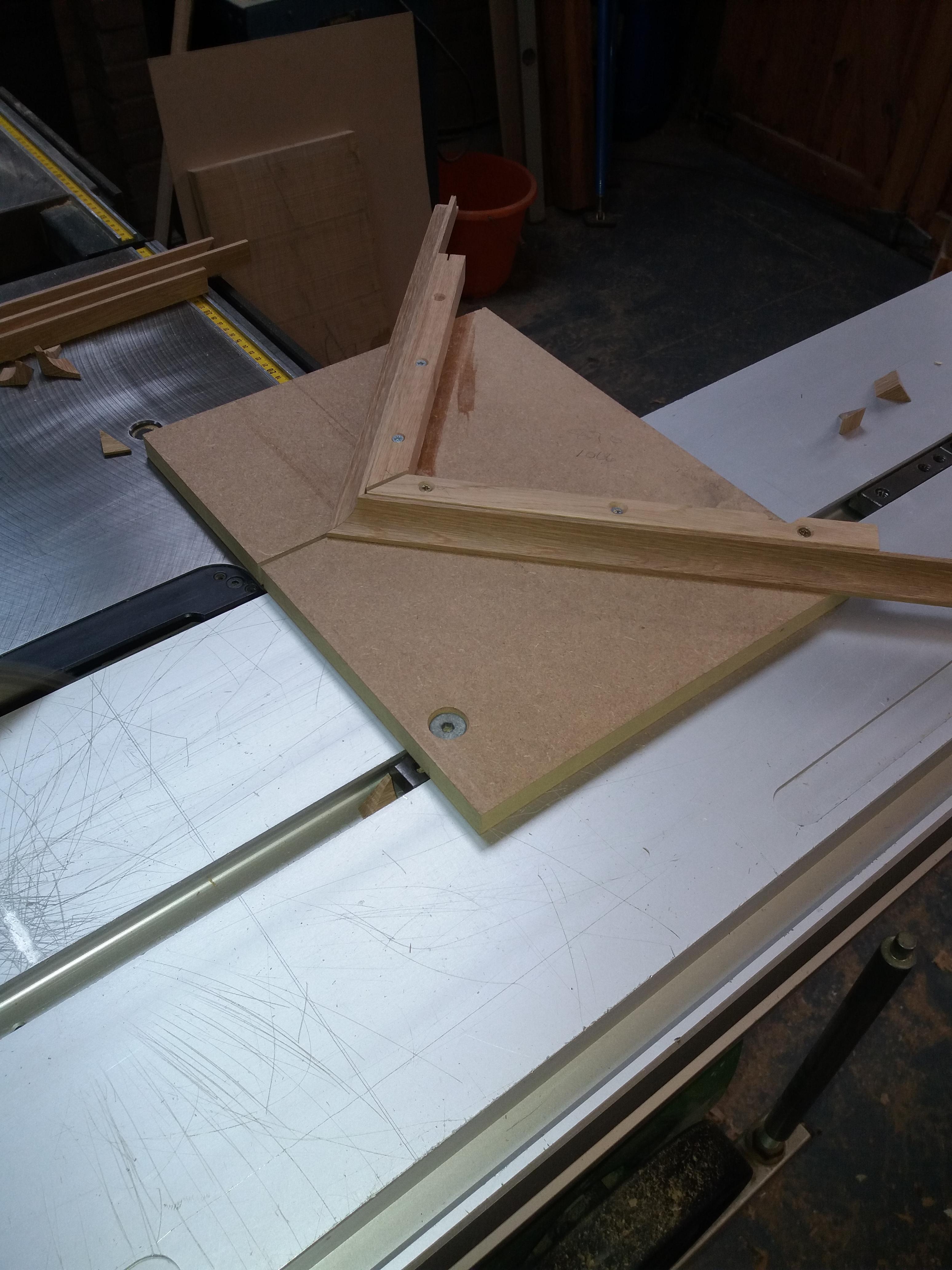
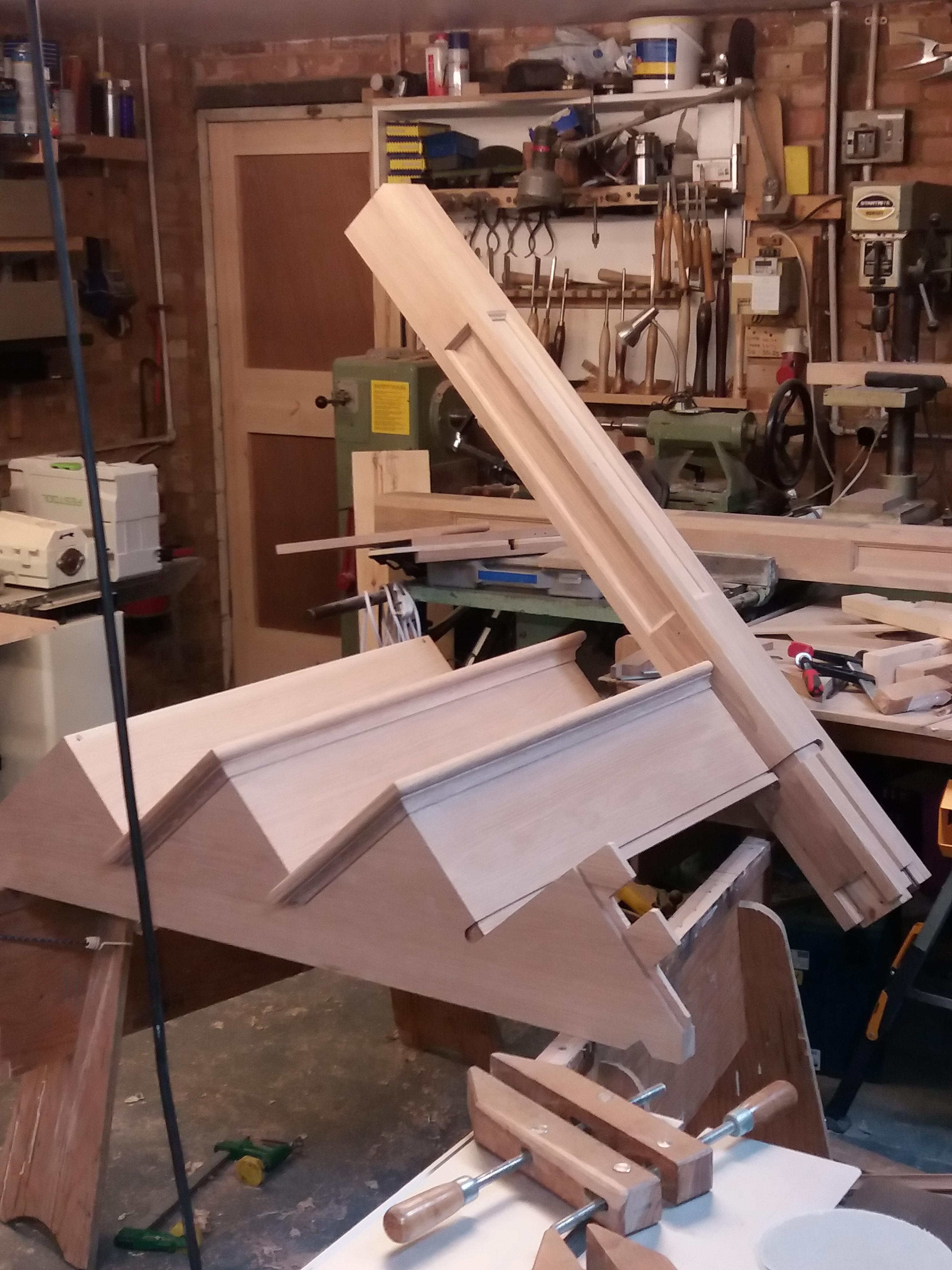
Re the assembly, I will show what photo’s I have taken, any questions please ask.
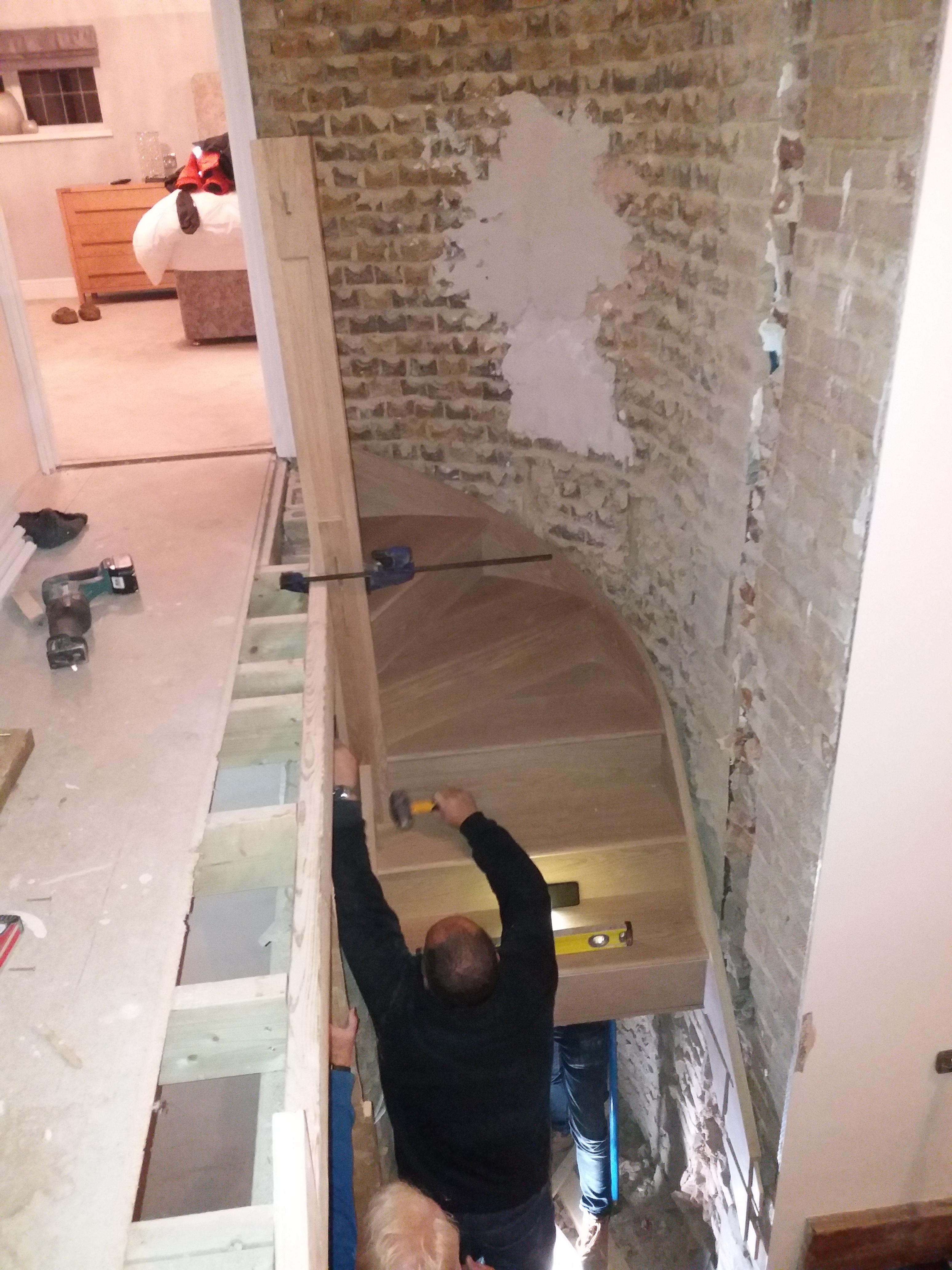
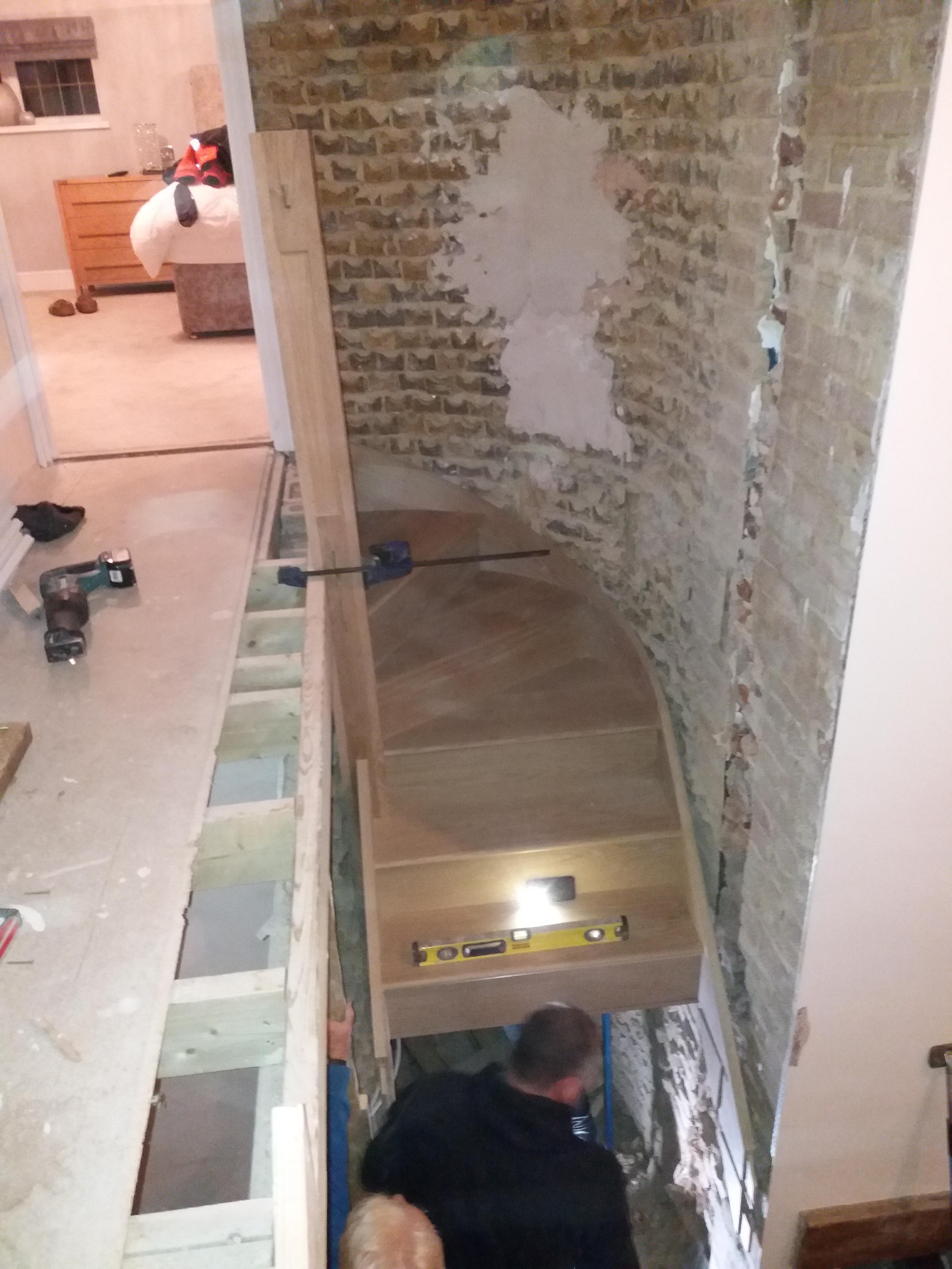
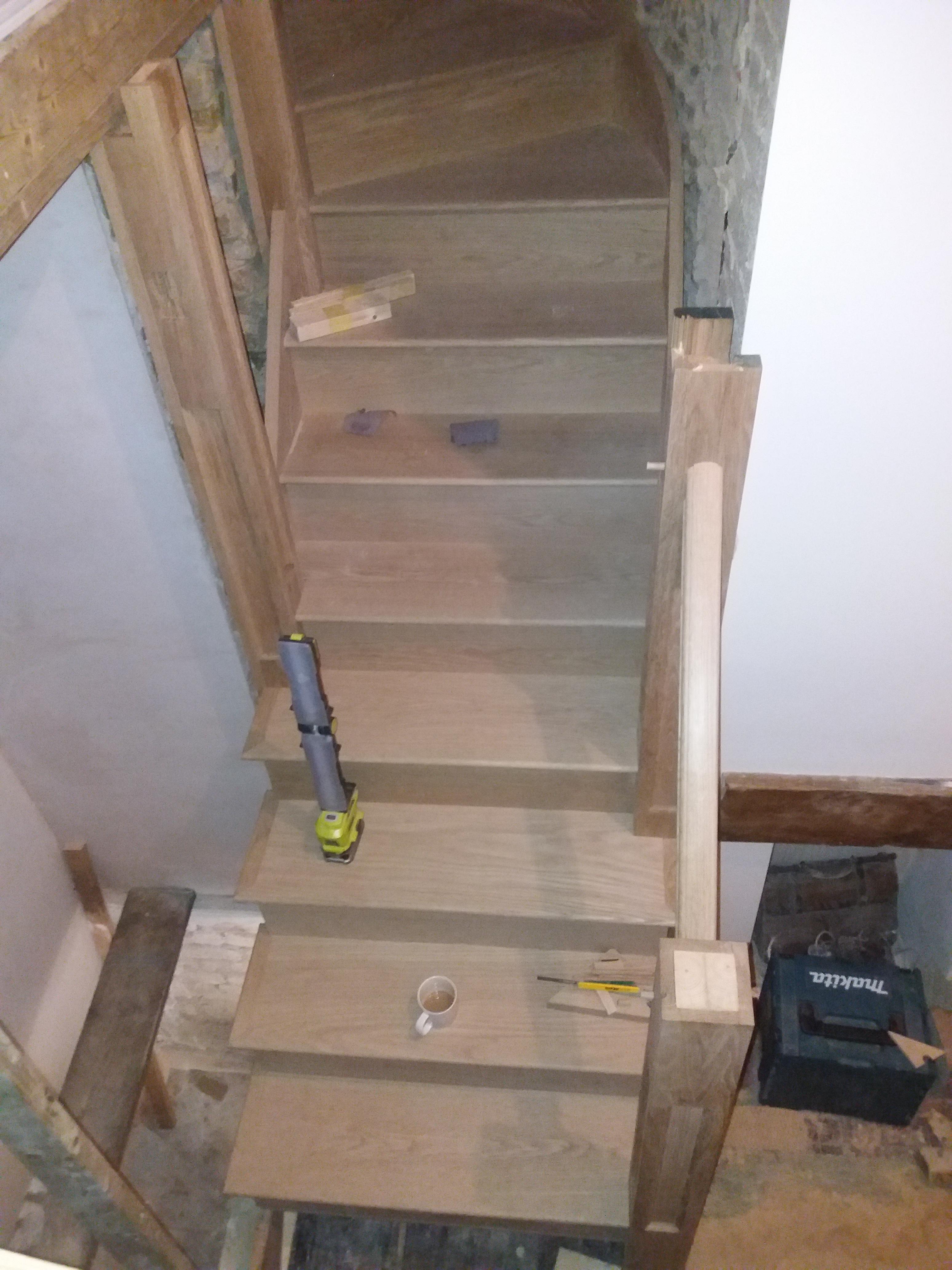
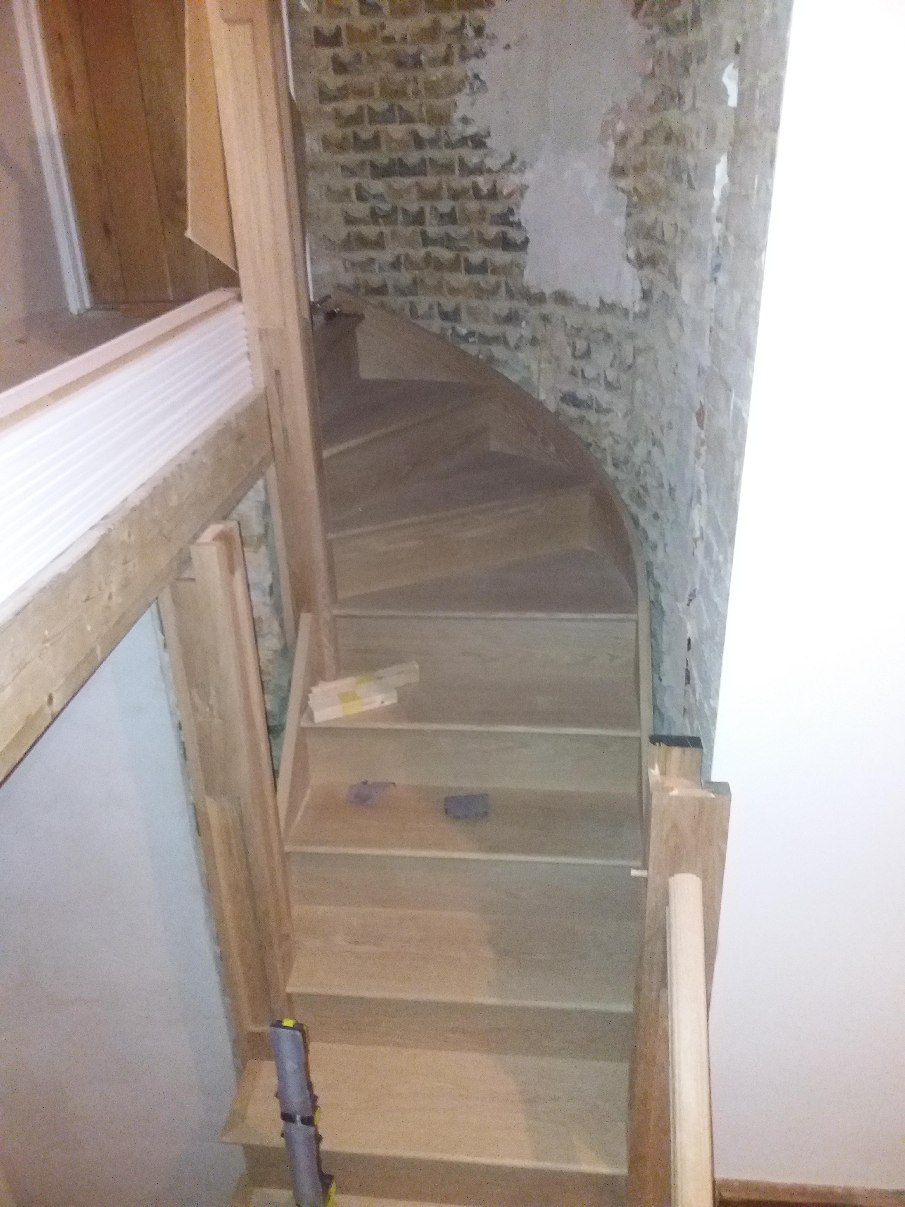
A bullnose step was made however the fitting of this awaits until a new floor is fitted and I can scribe the riser to the floor (its not level)
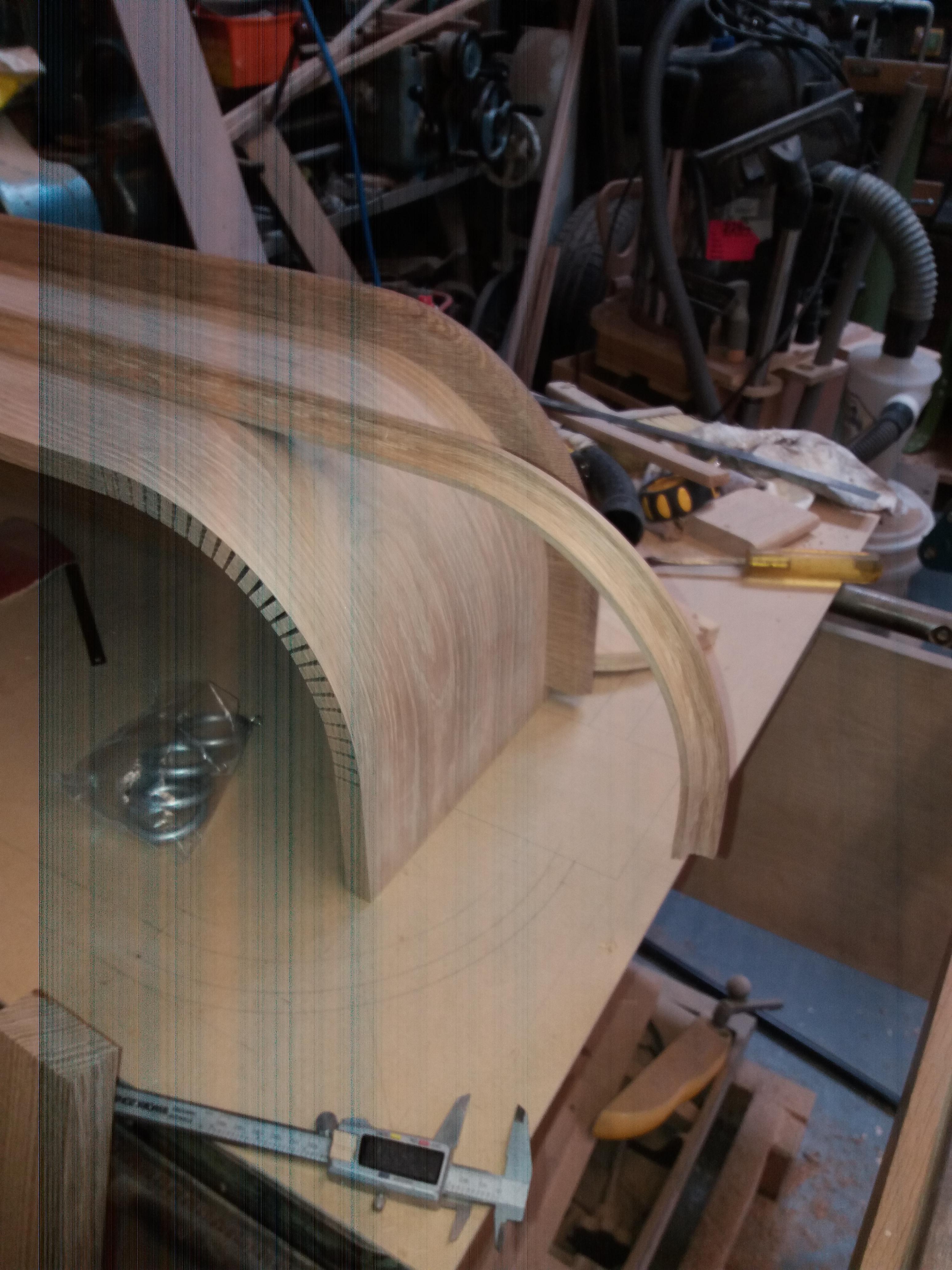
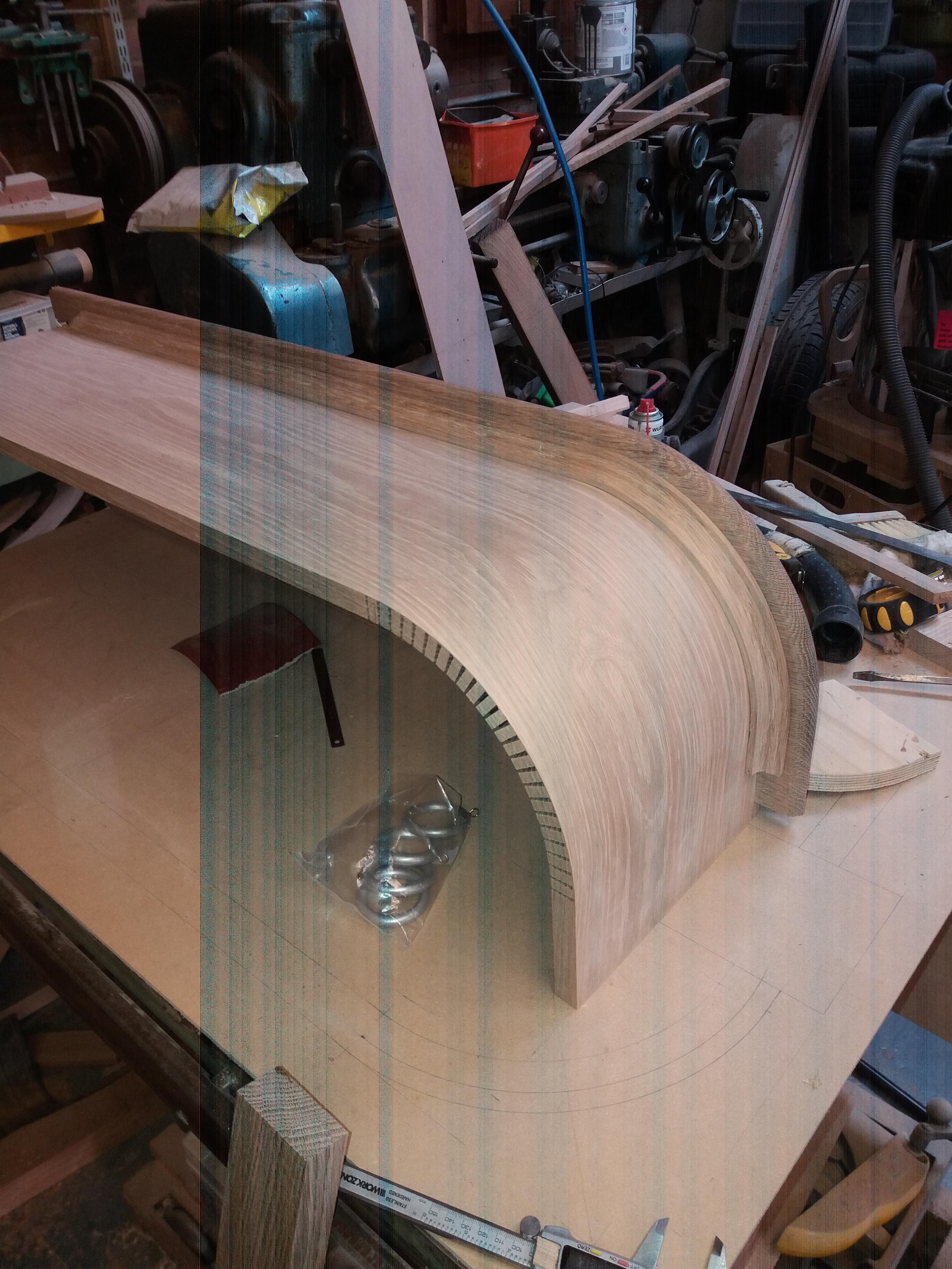
To follow is a the few photo’s I took re balustrading I know I should have taken more but I just get engrossed in the workshop and in essence I forget
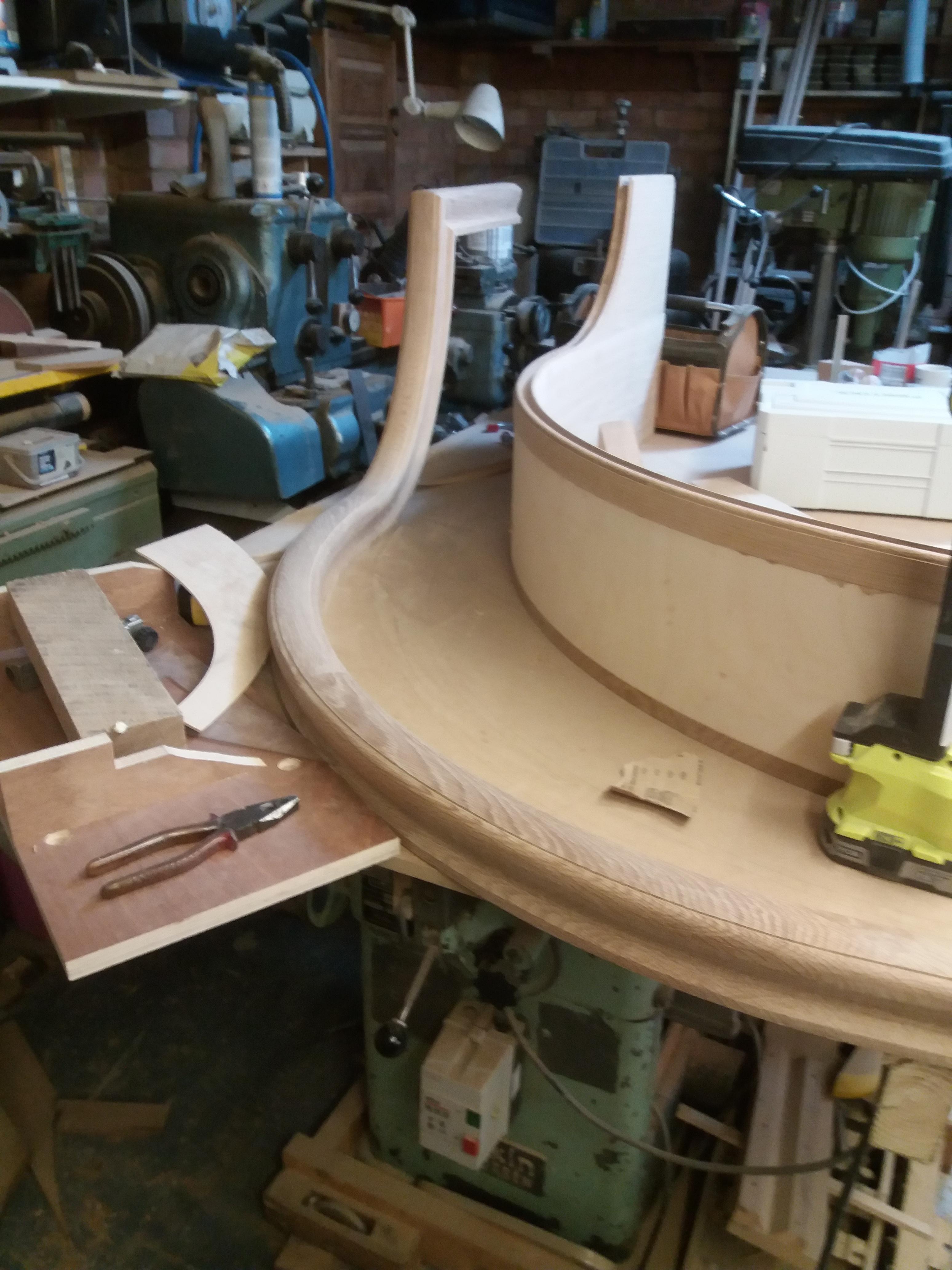
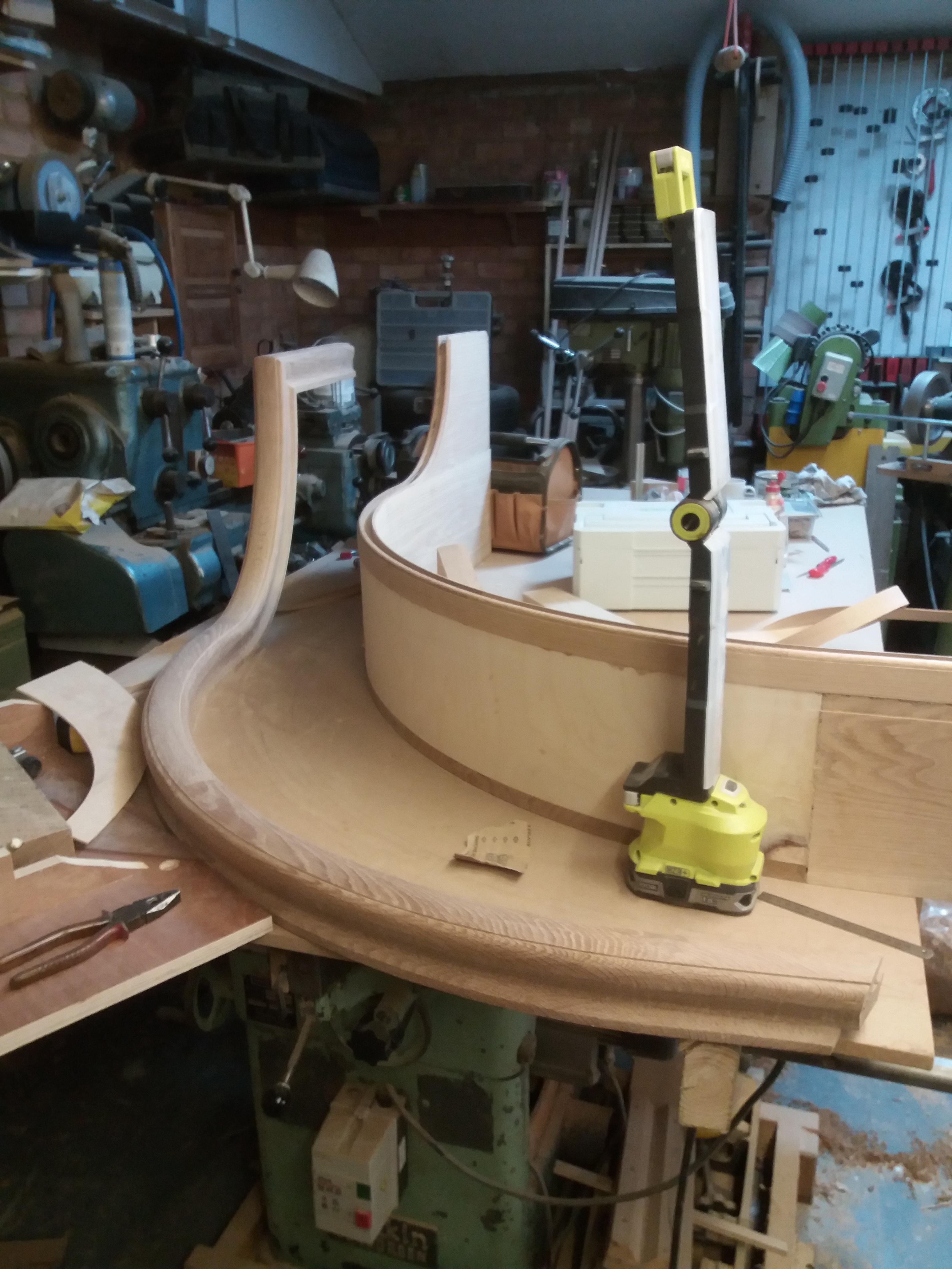
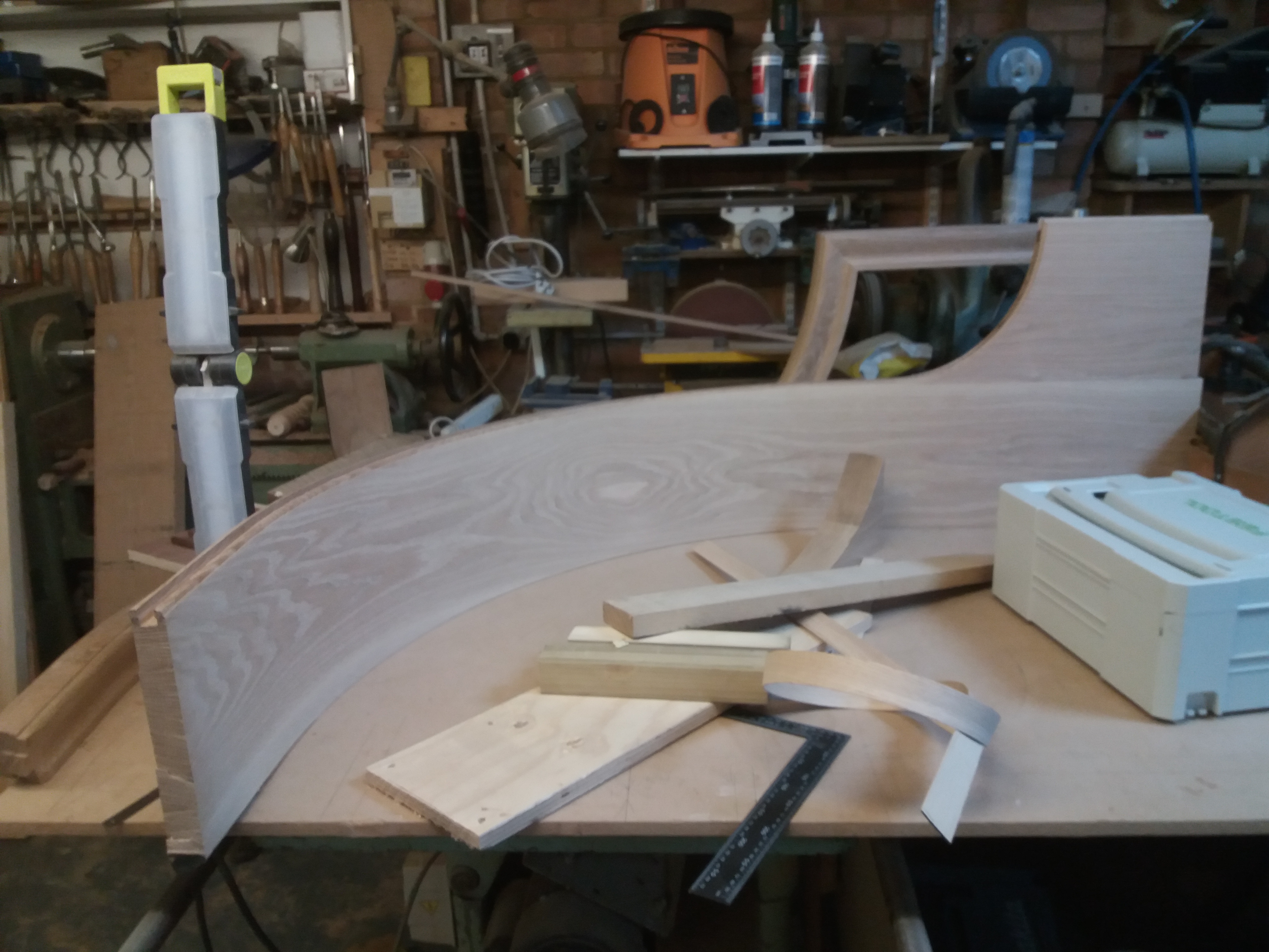
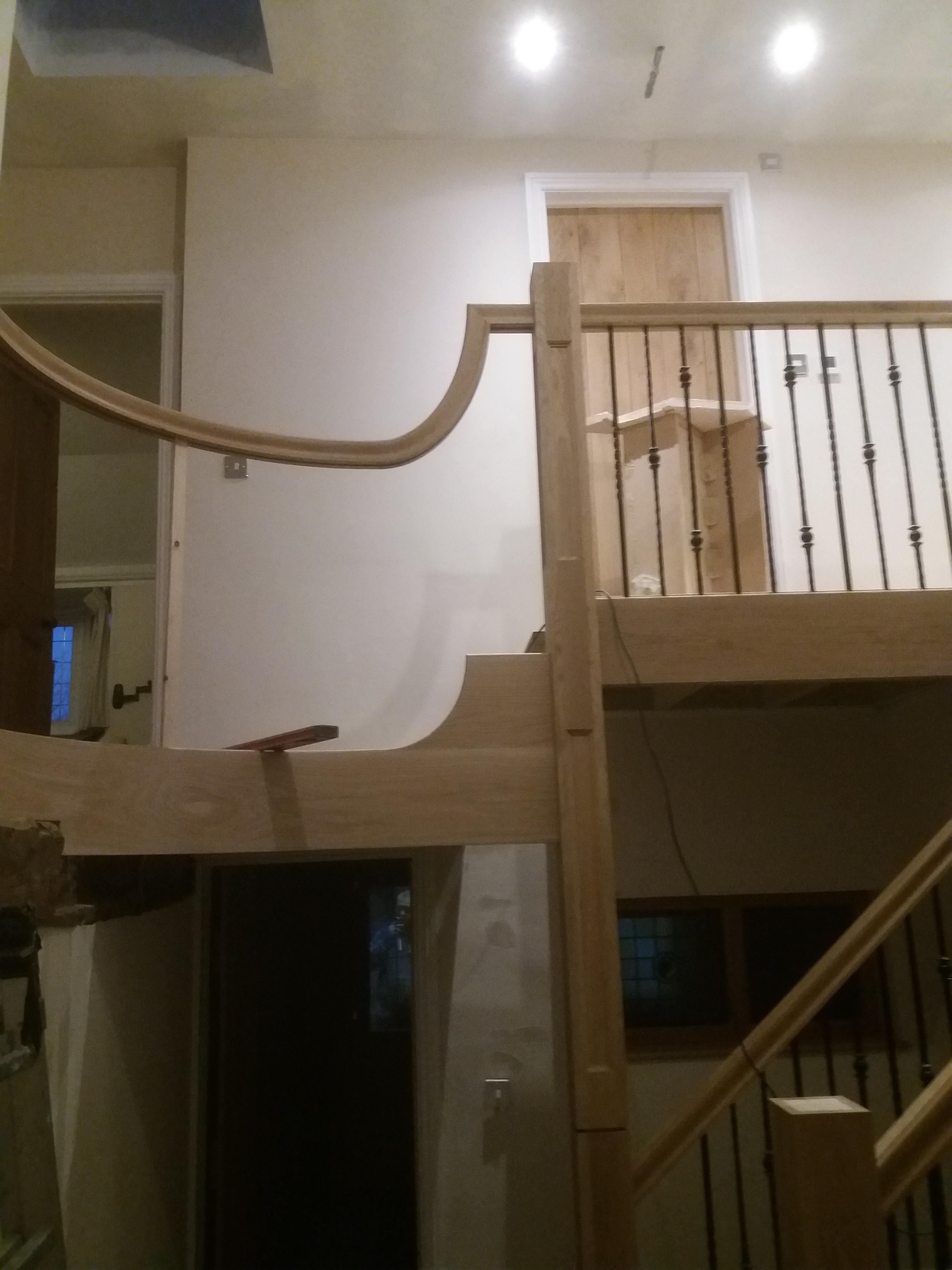
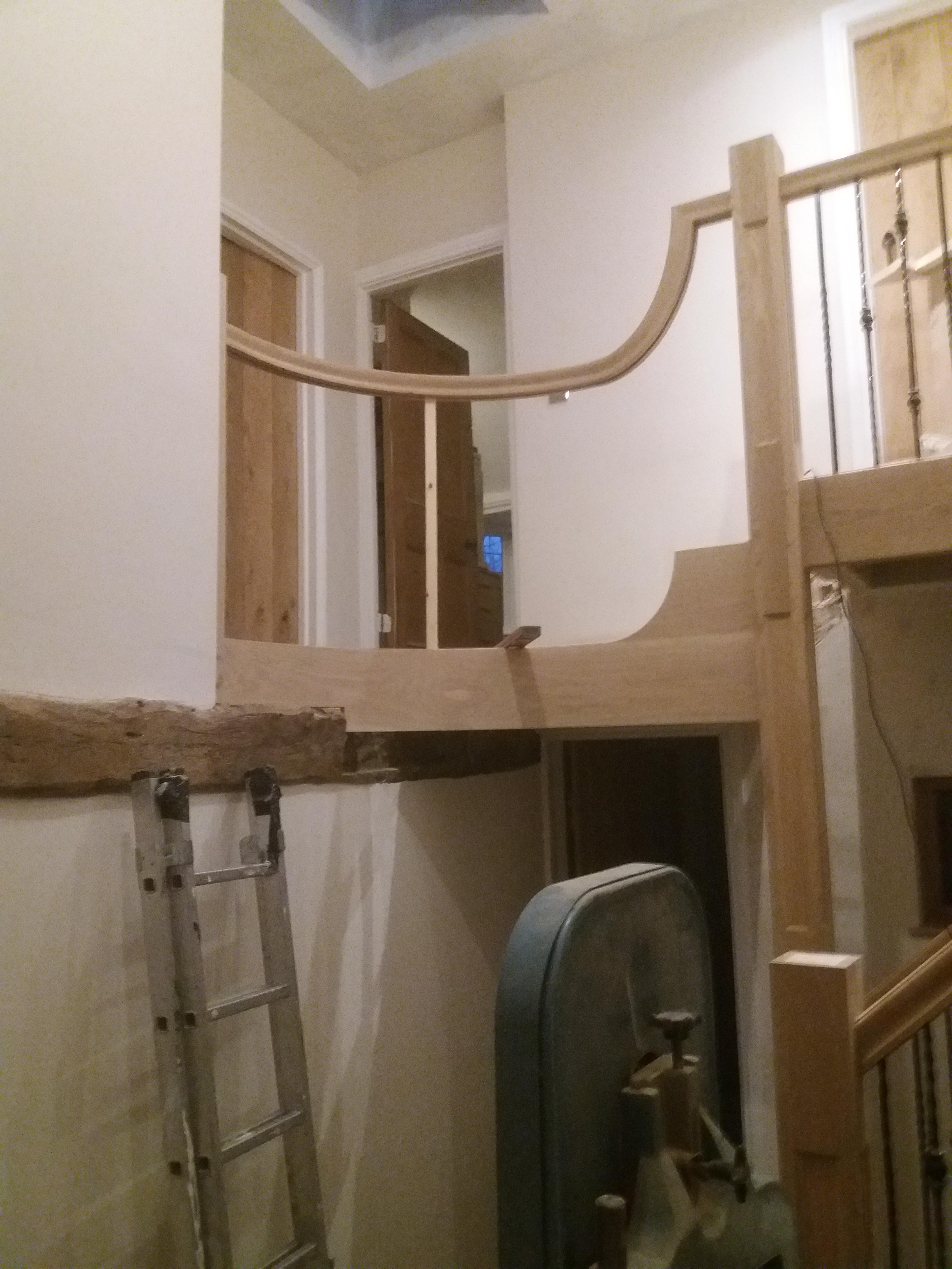
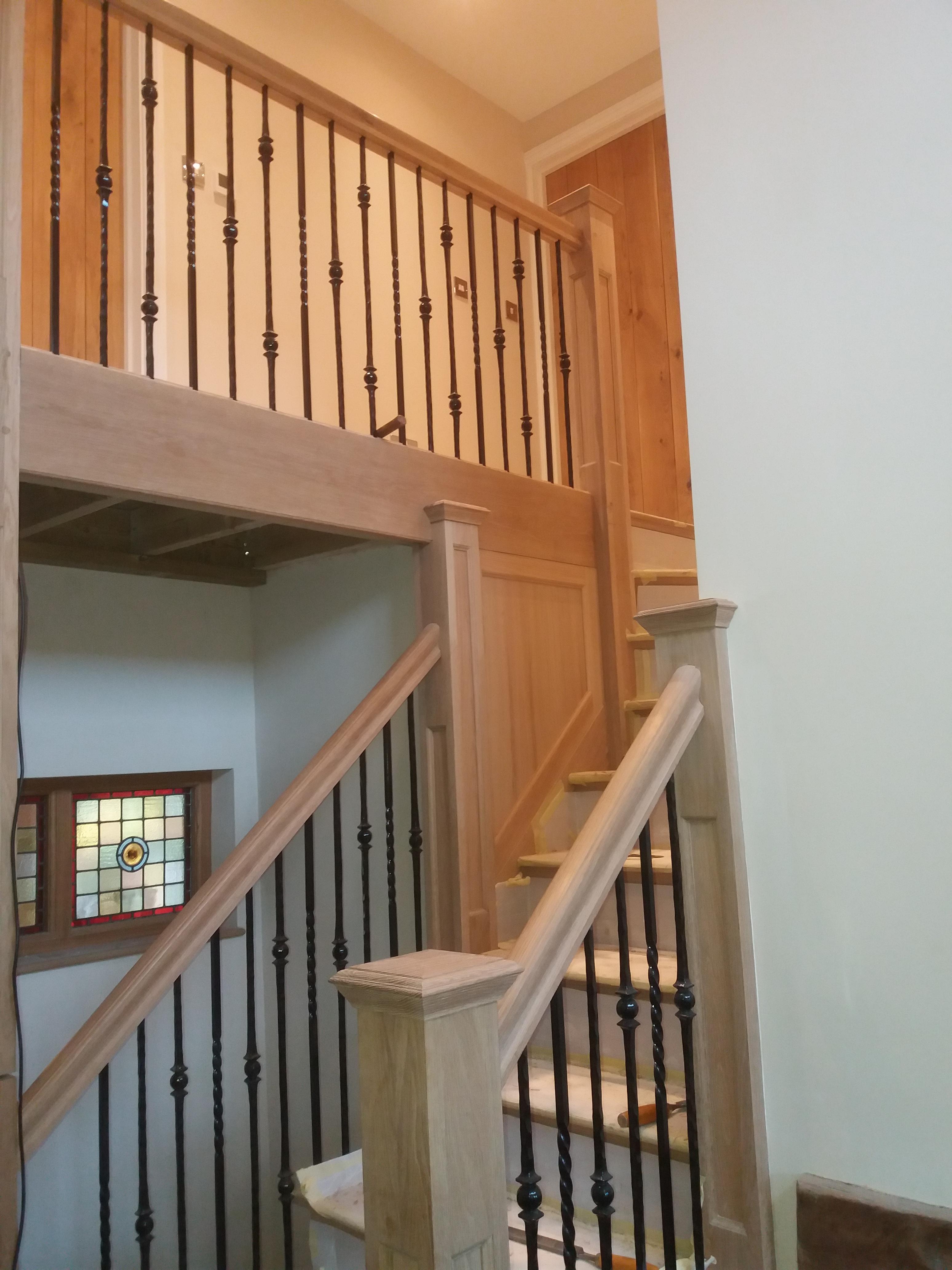
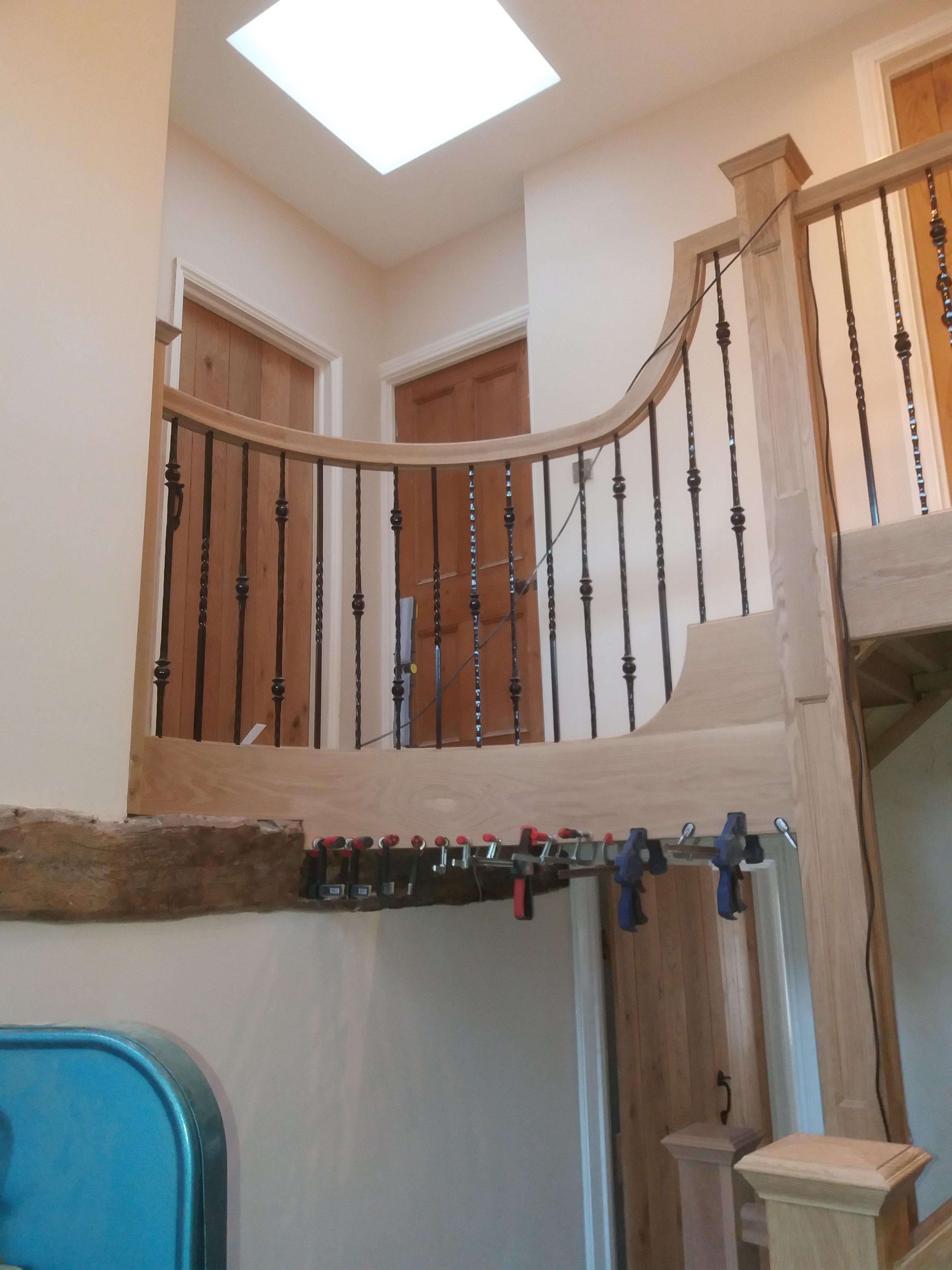
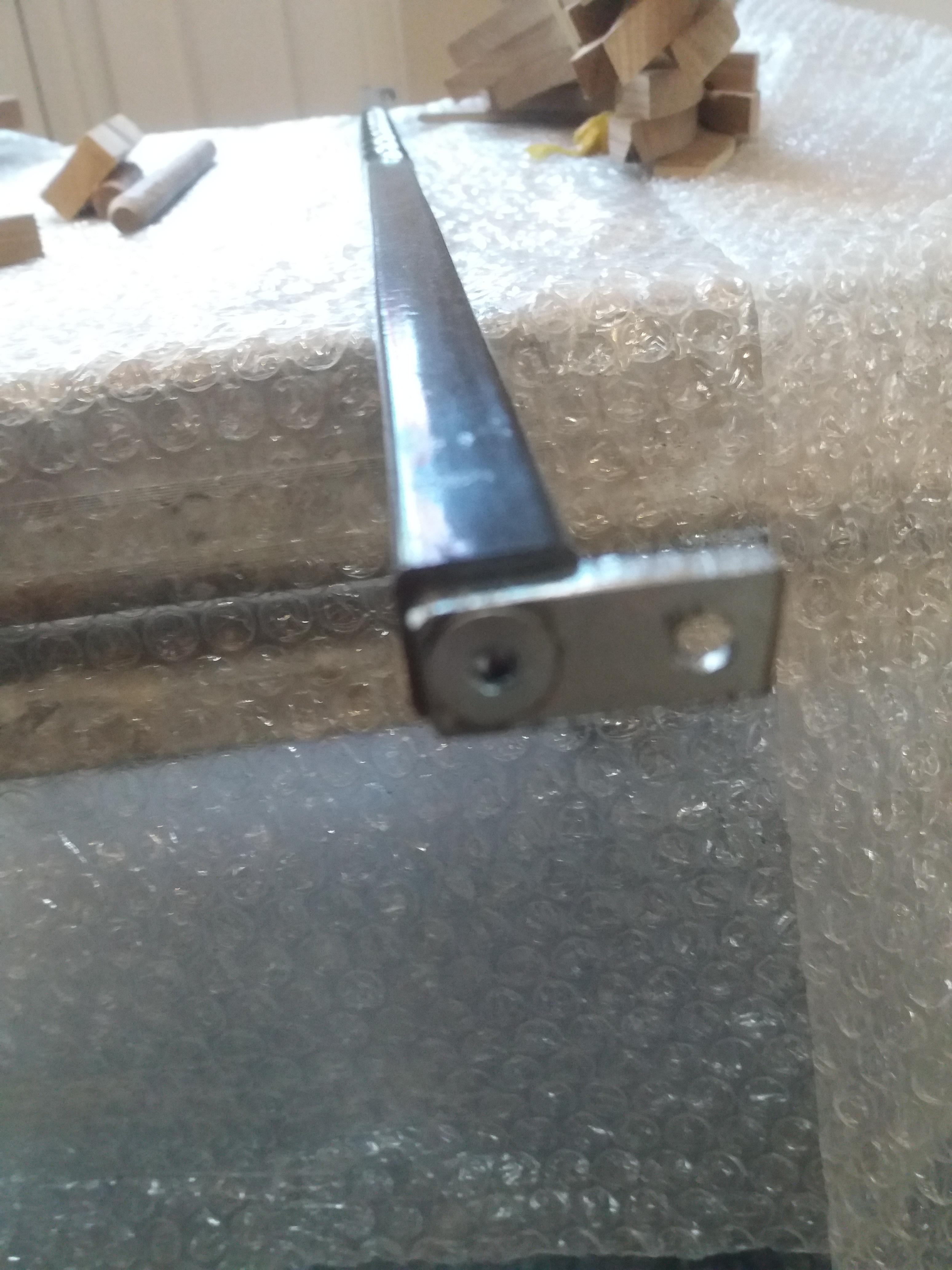
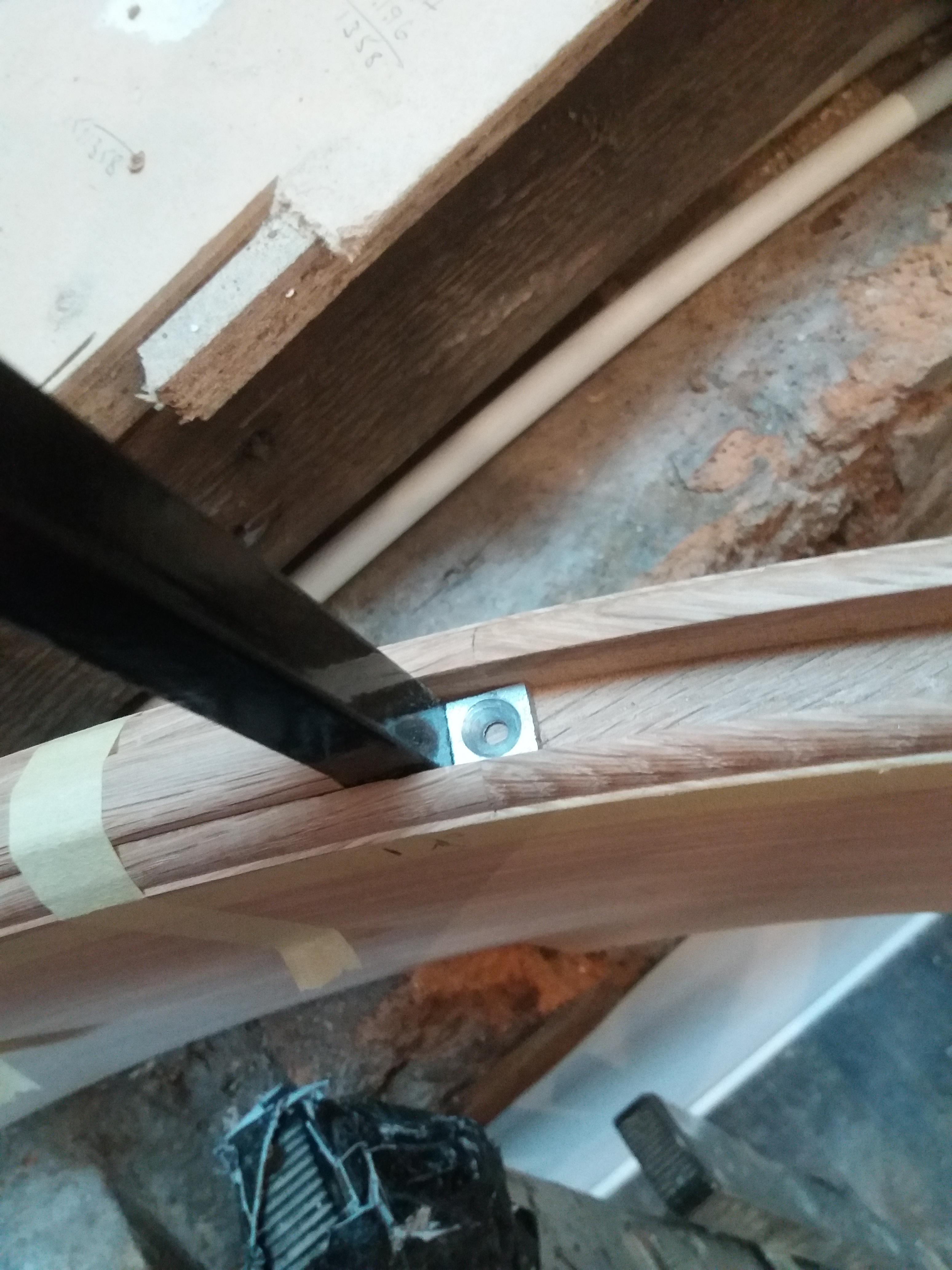
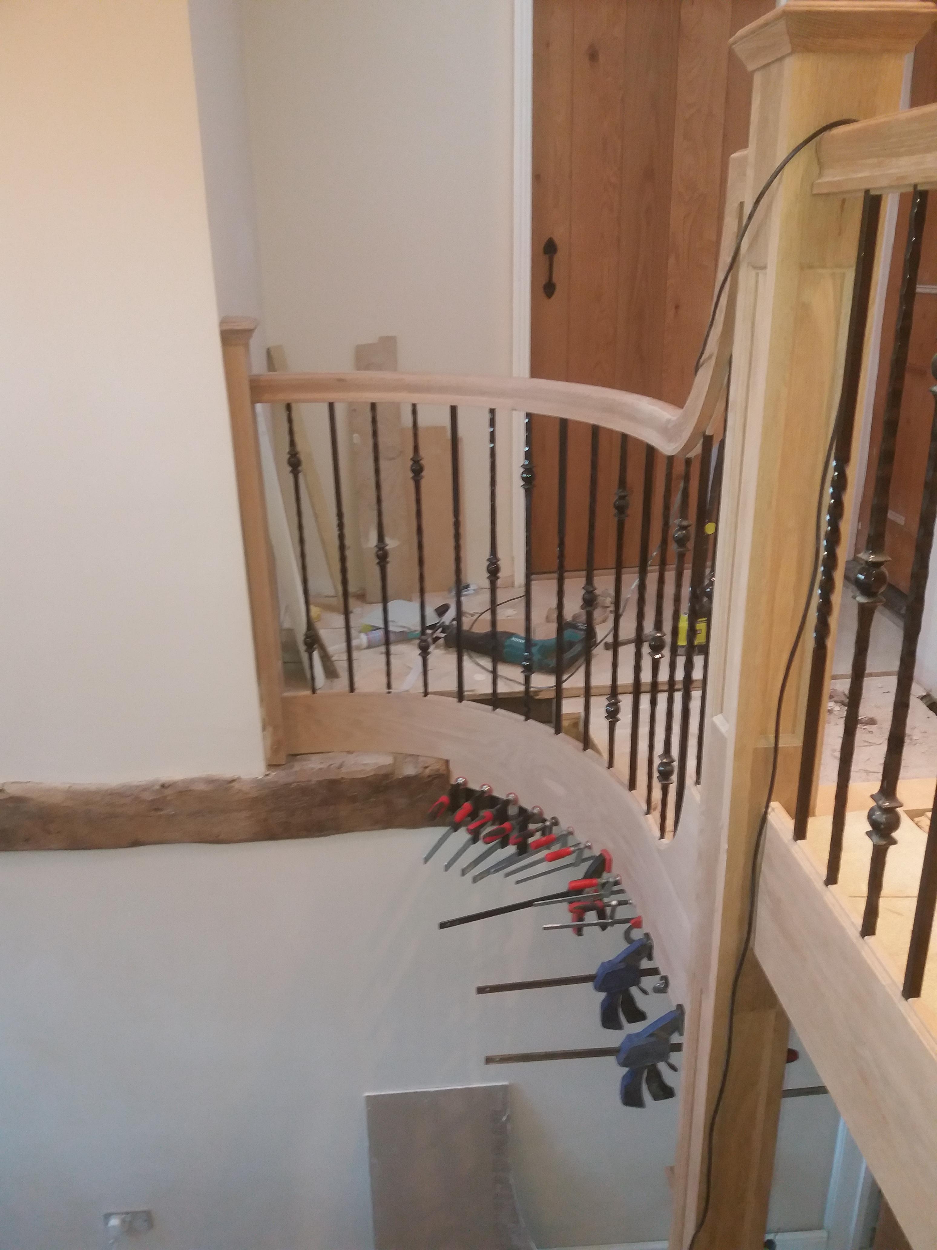
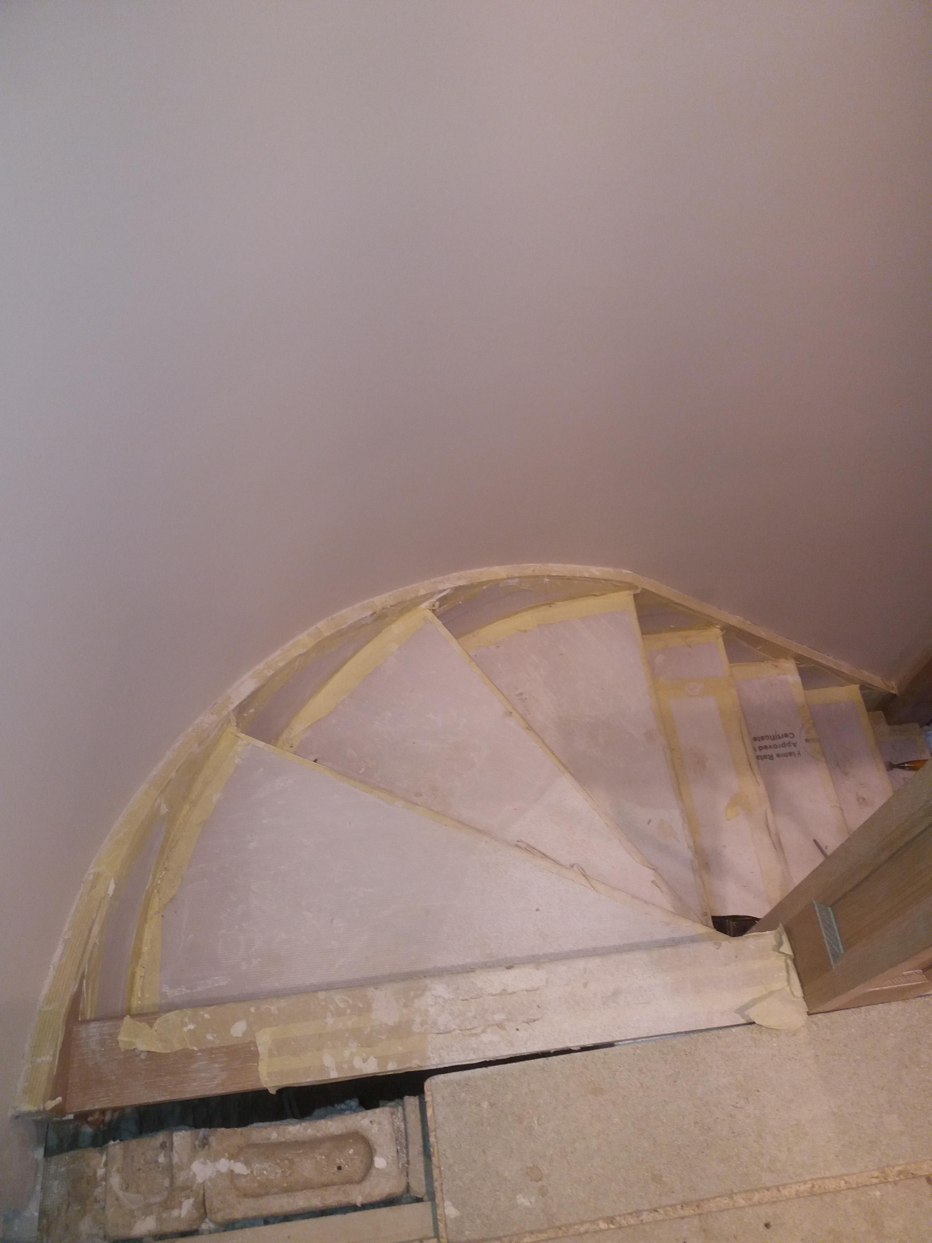
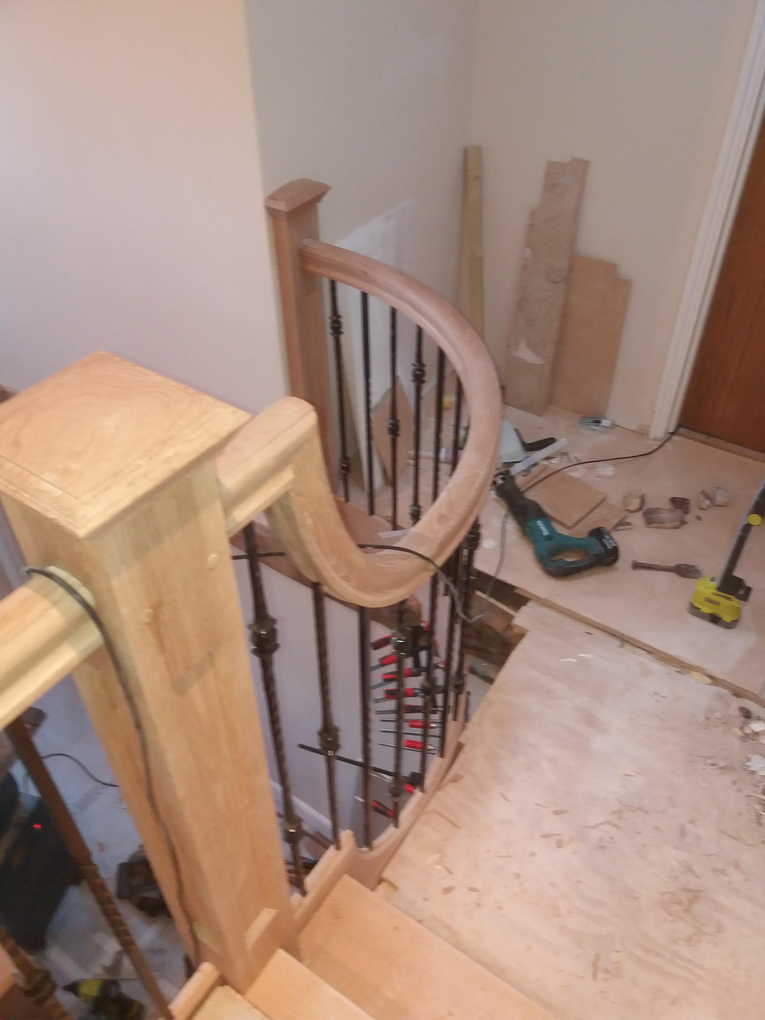
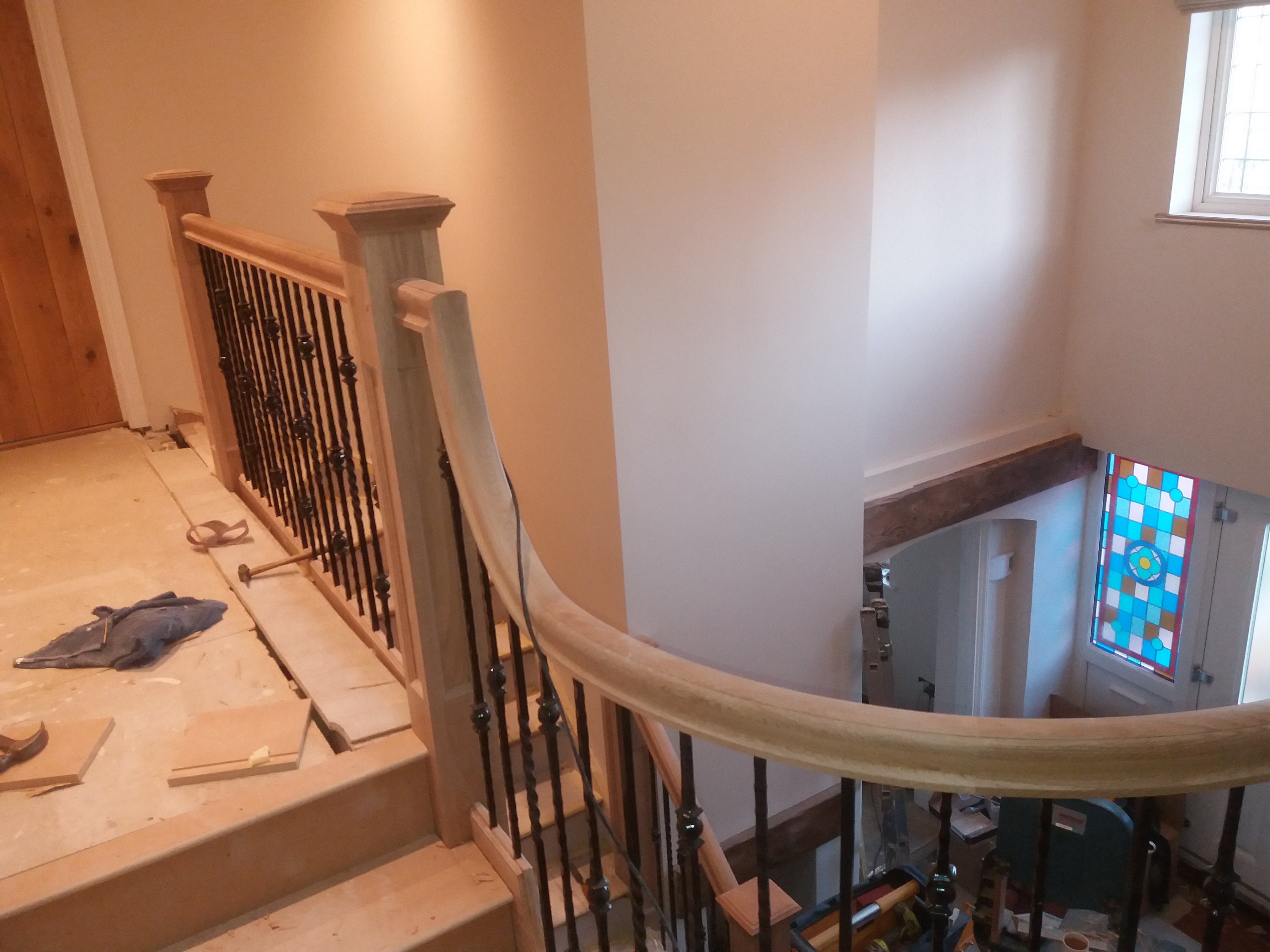
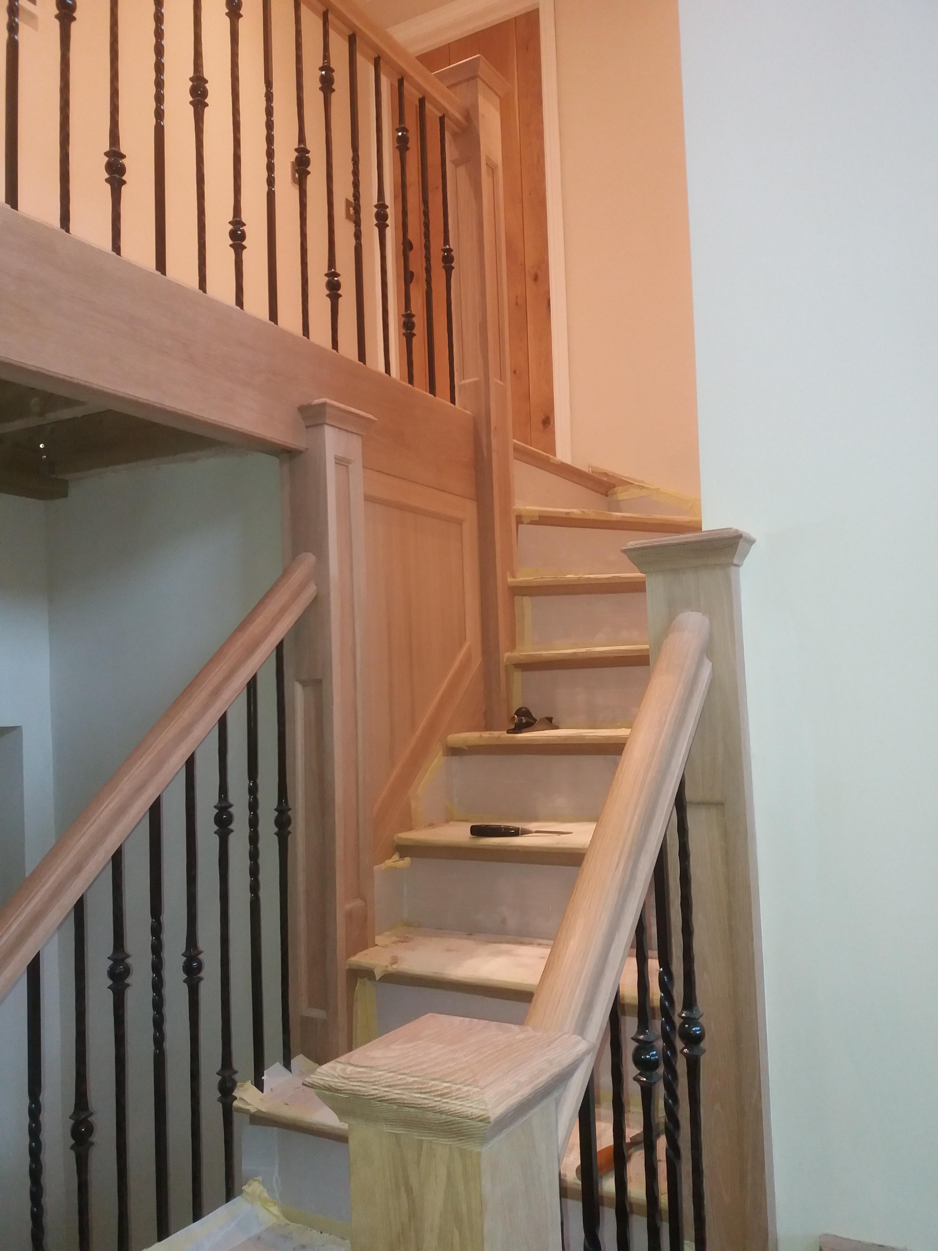
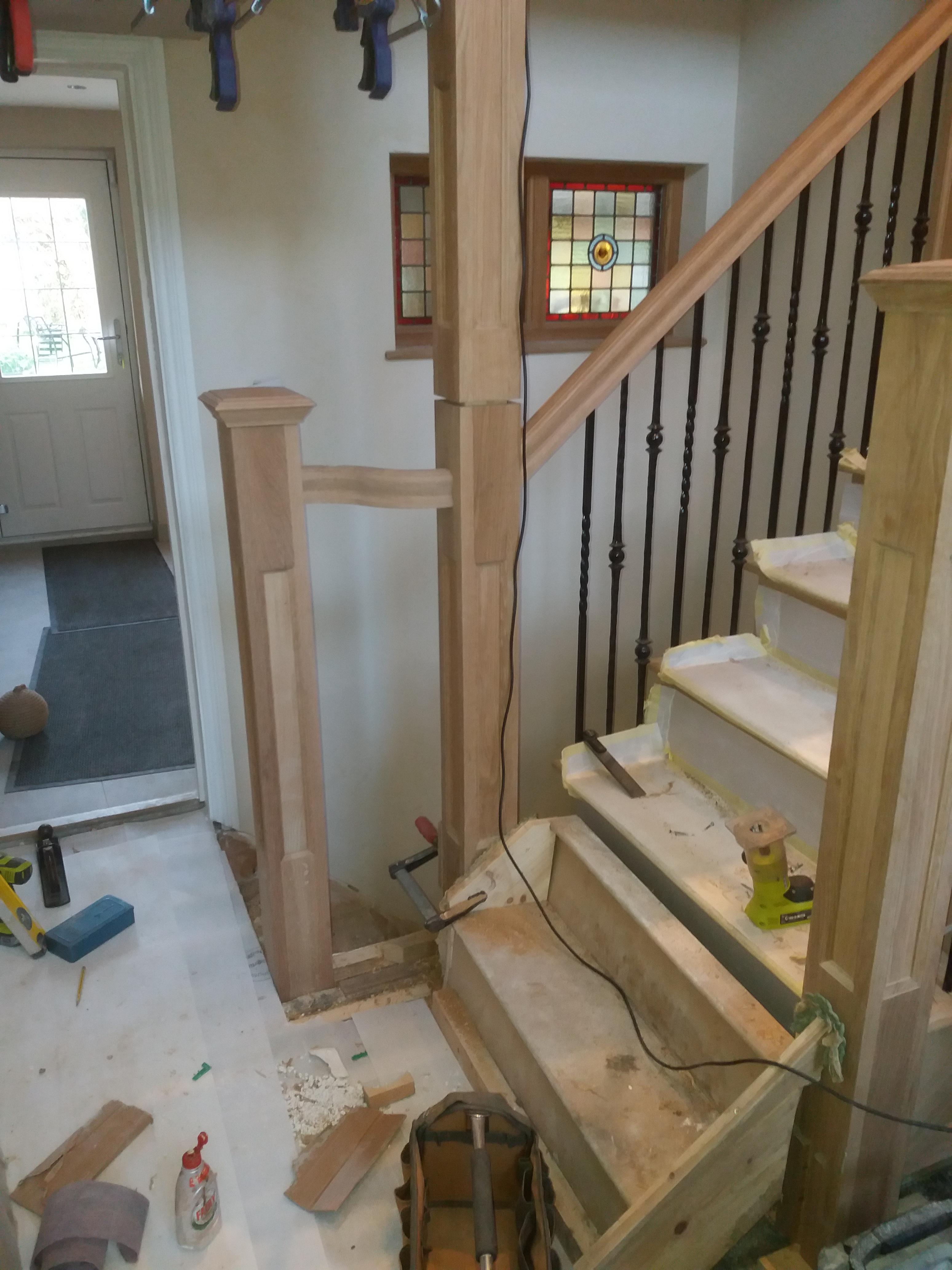
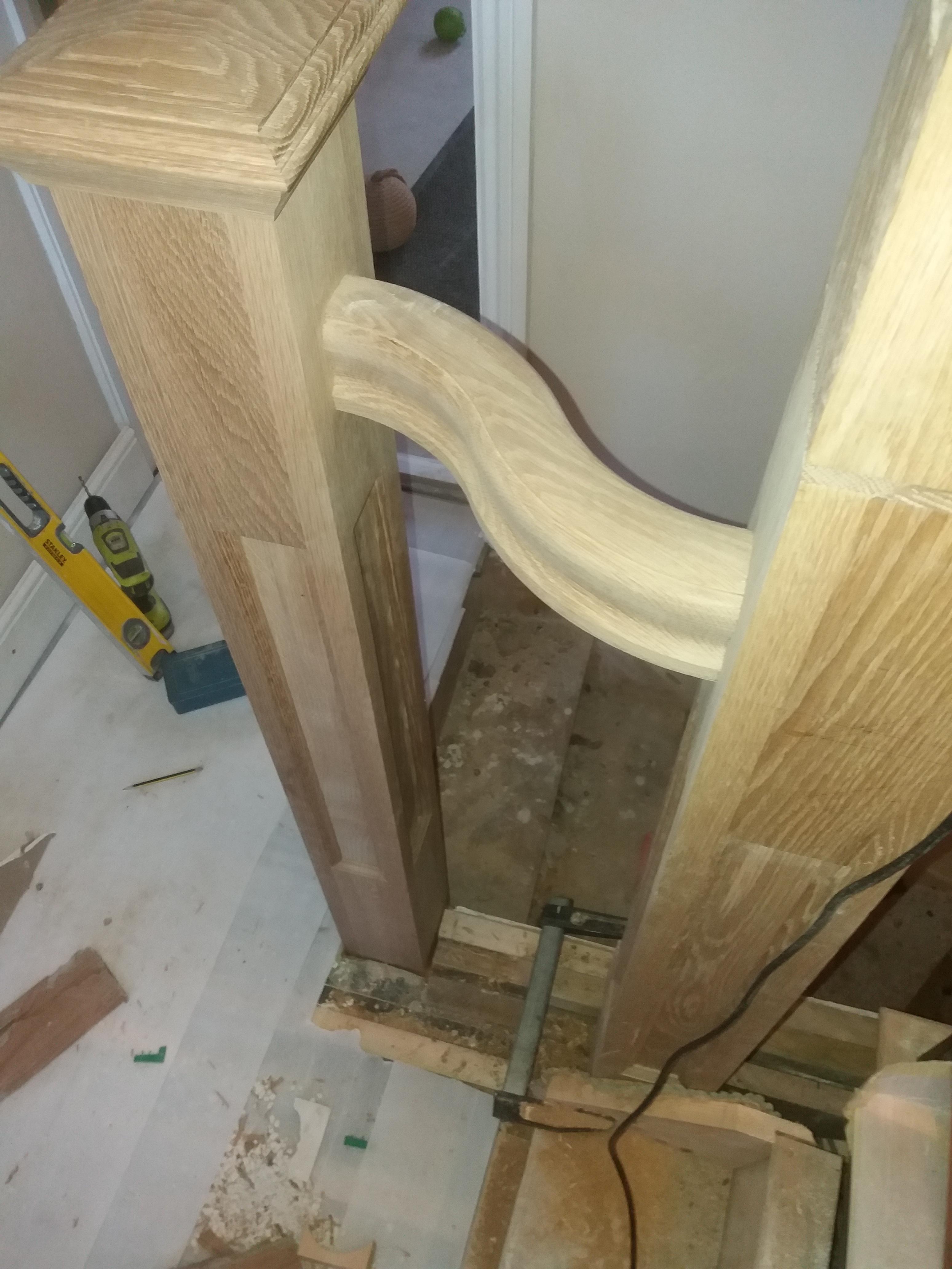
Currently stalled from the final finish as waiting for some slightly longer wrought ironwork being powder coated, when fully finished with snagging, final sanding and oiling I will post more photo’s
Please any questions, comments constructive criticism please don’t hesitate
Thanks
Chris
stair-advice-please-t118948-15.html
I would now like to go through the build of this flight of stairs
Firstly I would like to congratulate MikeG on his excellent build of his staircase and apologise in advance re the lack of pictures taken during the build.
This staircase and balustrade also acts as the support for the upper landing with the client wishing to maintain a view to some original leaded windows found in the property (which dates from the 18th century and was originally a pub/Inn) and which I have previously restored and framed in oak.
In addition beneath the main stairs is another flight which accesses the cellar and was extremely difficult to design owing to the limitations of the floor space area available
All the newels are constructed from 90mm square u/s softwood (made up of two pieces of 50mm glued back to back to prevent and movement. These were then clad in 20mm panelled oak creating 130mm square newels
Hope the pictures help in understanding this


A full size rod in plan was created on an 8 x 4 sheet of mdf to locate all wall and wall corner locations and the radius in plan.
From the rod a jig was set out and built out of ply, 2x2’s and 3 layers 6mm mdf glued together and clamped with ratchet straps to facilitate making the curved string (sorry no photo’s of this however I still have the jig if anyone any pictures).
Upon making the jig it was then placed on the rod and riser lines of the cured section projected onto the jig followed by tread lines, in essence I turned the jig into a curved rod which included the top and bottom lines of the string.
As this setup was too big for my airbag and also the reason for three layers of 6mm mdf I covered to area of the string on the jig with clear packing tape then laminated 4mm birch ply to a thickness of 28mm. This was done in two stages with the first stage being glued on top of the second stage in an attempt to eliminate springback.
Lengths of materials/offcuts kicking around the workshop were utilised to clamp the ply to the jig, I also glued strips of hardboard with CA to these offcuts on the outer edges to spread the clamping effect.


Once the ply had dried I resawed a piece of oak to 5mm on the bandsaw and ran it through the drum sander down to 4mm. This again was placed on the jig and all clamped up again

When everything was fully cured the jig was used as a setting out rod for the curved string and a reverse curved base was made for the router, the base had a straight edge at a right angle to the curve to allow it to run alongside of another straight edge


The riser housings were created in a similar way with underside wedge room also being routed (again a lack of pictures here). The housings in the upper newel were also routered and a dry fit was attempted. This is where working alone can be a right pain trying to balance/support everything to check all the joints.


This whole upper curved section was glued and wedged, in addition I screwed the treads through the back of the curved string to keep everything tight. (both treads and risers are made from solid oak as opposed veneered mdf for the risers)
I then made a short section of two treads with closed strings which went against walls, this was attached to the curved string with a series of dominoes


To further make this joint more secure I routered a couple of 30mm x 6mm deep grooves into the back of the curved and straight string and glued some appropriate strips into the groove to improve strength.
This assembled upper section was to be jointed into two newel posts half way up the full stair where it came into contact with walls (all will become evident as I proceed).
The next stage was the lower section which was to be cut or open string. I would have liked to have included brackets to the design as I think they enhance a stair plus they can hide a multitude of fixings however, on this job it was not to be however, I did incorporate mitred breadboard ends to all the lower treads. Again I did not photograph the construction of the cut string but have a sketchup of how the construction went


All joints were fitted and as much of this section was glued in the workshop to as larger sections as were practicable to facilitate transport and access. Scotia moulding was machined added to the underside of the treads.
NB, on a cut string to secure the riser a screw can be used behind the scotia and behind the tread prior to it being fitted


Re the assembly, I will show what photo’s I have taken, any questions please ask.


A bullnose step was made however the fitting of this awaits until a new floor is fitted and I can scribe the riser to the floor (its not level)


To follow is a the few photo’s I took re balustrading I know I should have taken more but I just get engrossed in the workshop and in essence I forget


Currently stalled from the final finish as waiting for some slightly longer wrought ironwork being powder coated, when fully finished with snagging, final sanding and oiling I will post more photo’s
Please any questions, comments constructive criticism please don’t hesitate
Thanks
Chris


