


9fingers
Established Member
I have a Woodpecker Router Lift http://www.woodpeck.com/unilift.html bought back in the good old days of more than 2 US$ to the pound and fitted with a Flex router. (Flex is the EU branding for the Porter Cable make that is popular in the USA). A bit like this one http://www.portercable.com/Products/Pro ... ctID=11102
The lift is very good but being American it is calibrated in 0.001" divisions and 1/16" per turn. The fine graduations can be difficult to see especially with a some sawdust on the table and it is easy to loose count when turning the handle. So I decided to treat myself to a Digital Readout (DRO) Scale from http://intelligentworkshoptools.co.uk/i ... &cPath=430 whilst at Cressing Temple over the weekend.
Fitting was fairly straightforward and so I thought I would take a few photos and do a WIP whilst I was at it. Turned out to be rather a lot of photos in the end!
This is what you get in the box as well as a packet of screws & washers and 4 batteries - it uses two at a time.
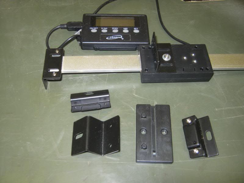
There is quite a choice of brackets to hold both the scale and the reading head.
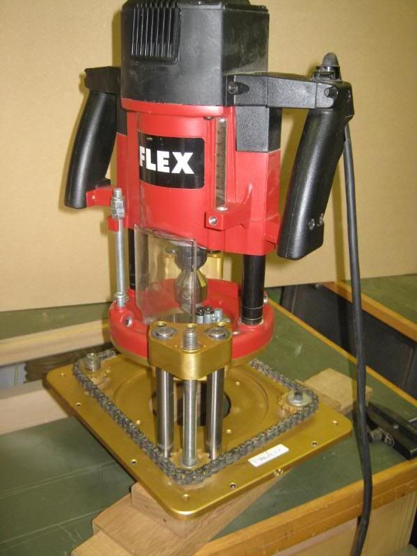
Here is the router and lift inverter ready for the fitting
Most combinations of router and lift are going to be similar and it just a case of looking around for a location where there are not obstacles and ideally a mounting point on the router body for the sliding head.
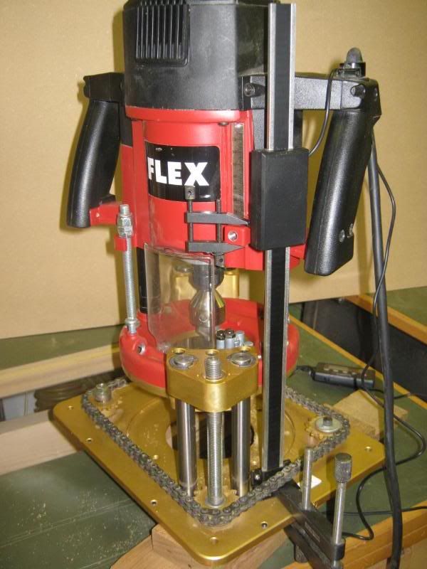
I used some clamps to try out the various positions and then to check that nothing got in the way over the full extend of the travel of both the lift and the routers own plunge mechanism.
Trial fit fully up
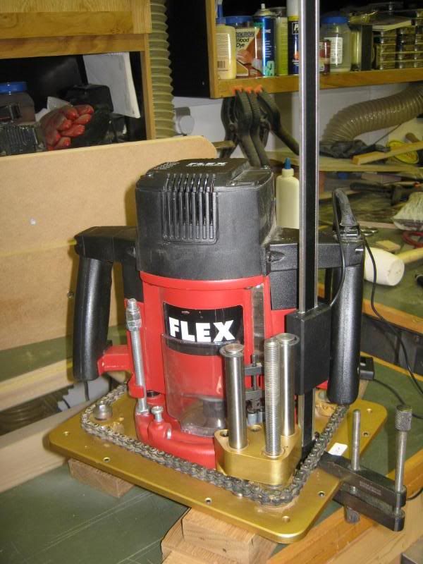
Trial fit fully down
Close up of base
Close up of the router body.
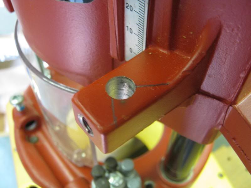
I chose to make use of the lug on the router body that is used for the depth stop when in upright routing mode. It has a convenient hole for a bolt which meant no drilling into the router or using a plastic part that could flex.
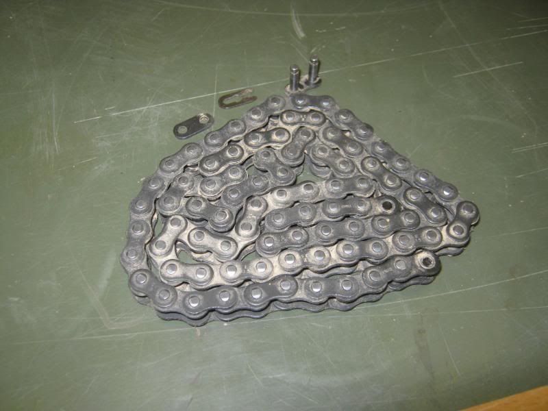
The chain has a spring link fitted just like on older bicycles so that came off with ease to give better access.
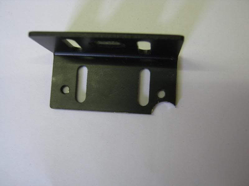
The mounting brackets have slots in to achieve final positioning so marking up with some pencil lines was adequate to start with.
Lift base location.
Router lug location.
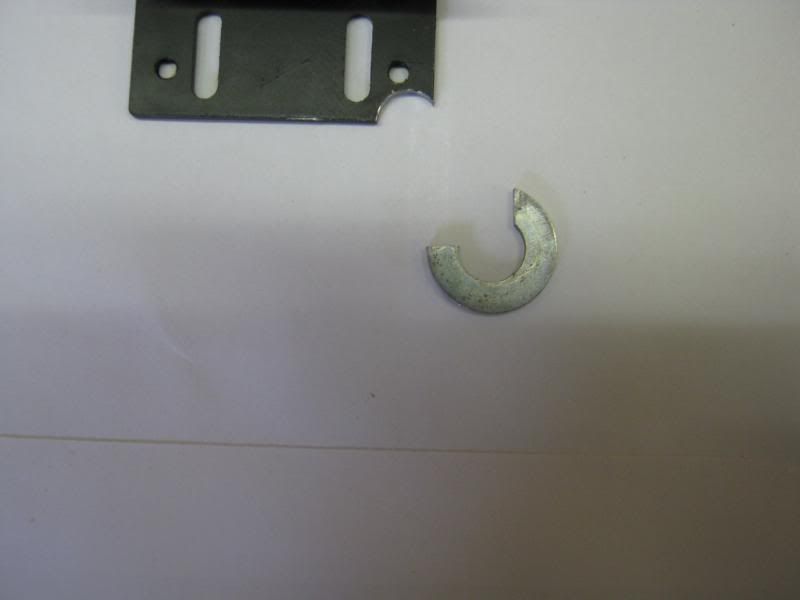
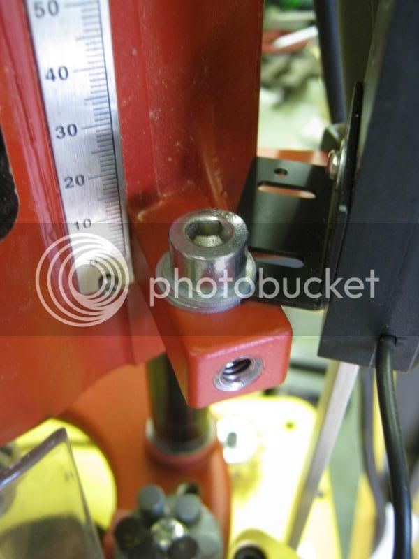
The mounting on the lug seemed a bit awkward until the eureka moment struck.
I nibbled some of the bracket away to accept an M8 bolt
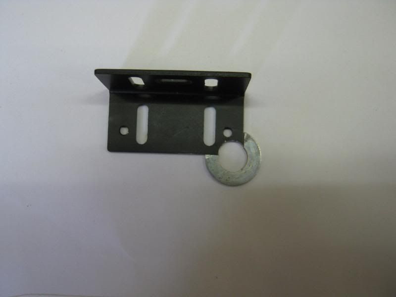
and then found a washer slightly thinner than the bracket and nibbled away at that too
With the two parts aligned and a full washer under the bolt head, and adequately rigid mounting was made
Bolted to the router for another trial fit.
Having confirmed the mounting position on the underside of the base, I drilled and tapped two m3 blind holes.
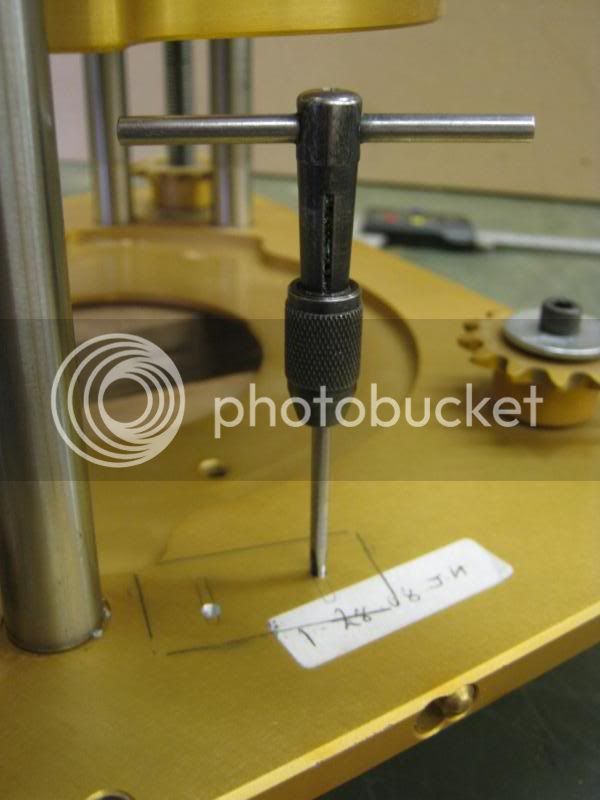
Don't worry if you don't have taps for thread cutting. You can drill right through and fit counter sunk screws from the other side instead. Just make sure the heads are fully recessed ans there are no burrs sticking up to mark the workpieces in use.
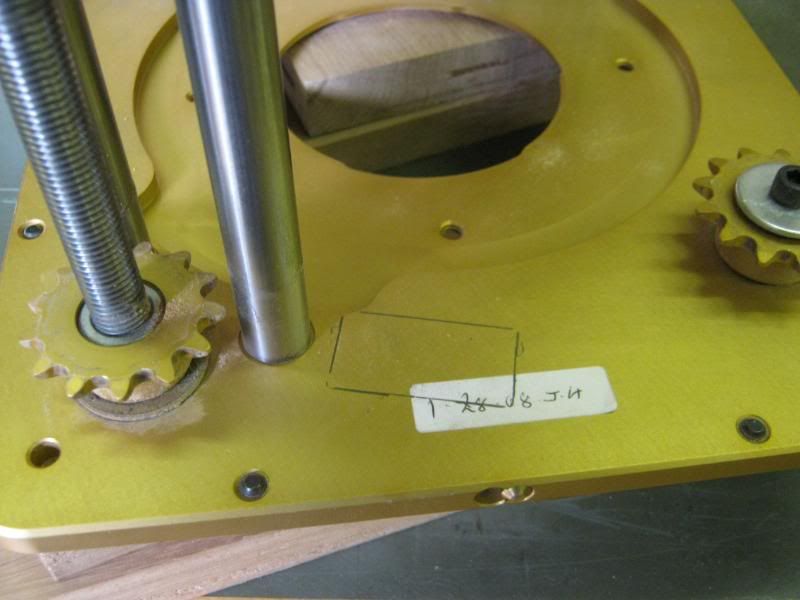
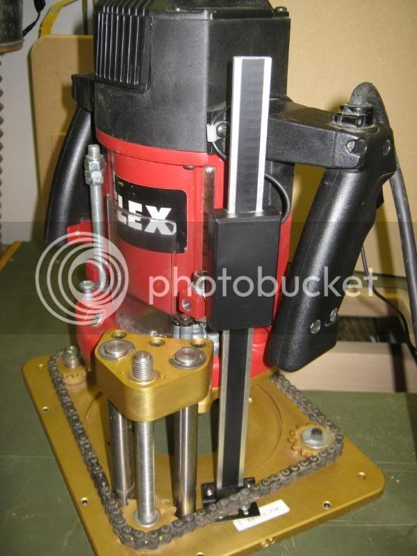
On the home straight now. All the mechanics completed, chain refitted (making sure I had not moved the sprockets out of line!), the excess length of the scale sawn off with a fine hacksaw and a final tidying up with a file.
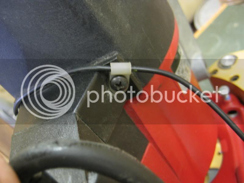
A couple of P clips fitted to tidy the cable and act as a strain relief.
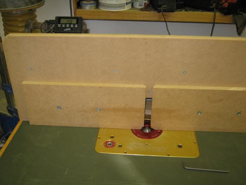
And all refitted to the table with the only evidence on view being the display attached to a fence clamp using the built in magnets. Top left.
I'll think of a better mounting another day.......
I have another longer scale to fit to my tablesaw fence. When the time comes I'll do another WIP
Thanks for reading this far without falling asleep!
Bob
Apologies for the rotated photos. They are all rotated correctly in my photobucket album but the img tags refuse to play ball.
Does anyone know how to sort this out please??
The lift is very good but being American it is calibrated in 0.001" divisions and 1/16" per turn. The fine graduations can be difficult to see especially with a some sawdust on the table and it is easy to loose count when turning the handle. So I decided to treat myself to a Digital Readout (DRO) Scale from http://intelligentworkshoptools.co.uk/i ... &cPath=430 whilst at Cressing Temple over the weekend.
Fitting was fairly straightforward and so I thought I would take a few photos and do a WIP whilst I was at it. Turned out to be rather a lot of photos in the end!
This is what you get in the box as well as a packet of screws & washers and 4 batteries - it uses two at a time.
There is quite a choice of brackets to hold both the scale and the reading head.
Here is the router and lift inverter ready for the fitting
Most combinations of router and lift are going to be similar and it just a case of looking around for a location where there are not obstacles and ideally a mounting point on the router body for the sliding head.
I used some clamps to try out the various positions and then to check that nothing got in the way over the full extend of the travel of both the lift and the routers own plunge mechanism.
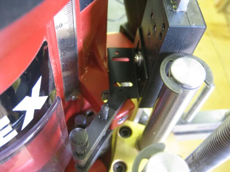
Trial fit fully up
Trial fit fully down
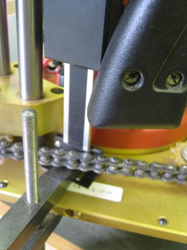
Close up of base
Close up of the router body.
I chose to make use of the lug on the router body that is used for the depth stop when in upright routing mode. It has a convenient hole for a bolt which meant no drilling into the router or using a plastic part that could flex.
The chain has a spring link fitted just like on older bicycles so that came off with ease to give better access.
The mounting brackets have slots in to achieve final positioning so marking up with some pencil lines was adequate to start with.
Lift base location.
Router lug location.
The mounting on the lug seemed a bit awkward until the eureka moment struck.
I nibbled some of the bracket away to accept an M8 bolt
and then found a washer slightly thinner than the bracket and nibbled away at that too
With the two parts aligned and a full washer under the bolt head, and adequately rigid mounting was made
Bolted to the router for another trial fit.
Having confirmed the mounting position on the underside of the base, I drilled and tapped two m3 blind holes.
Don't worry if you don't have taps for thread cutting. You can drill right through and fit counter sunk screws from the other side instead. Just make sure the heads are fully recessed ans there are no burrs sticking up to mark the workpieces in use.
On the home straight now. All the mechanics completed, chain refitted (making sure I had not moved the sprockets out of line!), the excess length of the scale sawn off with a fine hacksaw and a final tidying up with a file.
A couple of P clips fitted to tidy the cable and act as a strain relief.
And all refitted to the table with the only evidence on view being the display attached to a fence clamp using the built in magnets. Top left.
I'll think of a better mounting another day.......
I have another longer scale to fit to my tablesaw fence. When the time comes I'll do another WIP
Thanks for reading this far without falling asleep!
Bob
Apologies for the rotated photos. They are all rotated correctly in my photobucket album but the img tags refuse to play ball.
Does anyone know how to sort this out please??