A skewed infill panel plane

UKworkshop.co.uk

Help Support UKworkshop.co.uk:

This site may earn a commission from merchant affiliate links, including eBay, Amazon, and others.

IWW

Established Member
Joined
15 Oct 2017
Messages
400
Reaction score
330
Location
Brisbane
This was a drawn-out build, so I’ll go through it in a series of posts.

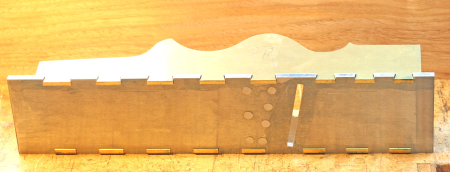
It’s my second panel plane project, the first was an all-steel version made from a kit which had the sides & sole roughed out. Rough is the operative word, and I had some bother getting the sockets cleaned out so the shoulders met neatly without filing away too much metal & making the fit really sloppy. I ended up with visible lines on a couple of the dovetails, as you can see.
1 pp.jpg


However, the body is rock-solid & it turned out a superb user, one of the best-functioning infills I’ve made to date, which begs the obvious question “why on earth make another one?!” I can’t provide a very convincing answer to that, but I did have one valid reason. I’ve been searching for a source of brass that is better for peening than the C385 “machineable” grade which is the only one I can easily obtain locally in plate/bar form. As part of this quest I bought some “H62” brass advertised on ebay The piece is 4mm thick, 300 x 100 mm, which I calculated would be just enough for the two sides for this plane.

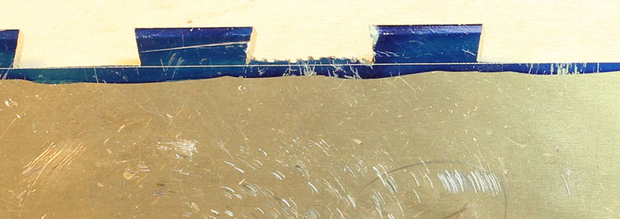
The different nomenclatures for brass used around the world is confusing to us lay folk, but H62 seems to be (roughly) the Chinese equivalent of C108, which British readers may recognise as a good cold-working grade. As soon as I got the piece, I cut a sliver from a waste area and gave it a beating:
2 C385  vs H62 b.jpg


The piece on the left is C385, and as you can see, it is in pretty poor shape by the time I spread the end to approximately twice its width. The H62, on the other hand, has been hammered to more than twice its original width with no sign whatever of failure. This looks very promising!

I had originally intended to make a “badger” plane, but decided against badgering it for a few irrelevant reasons. However, I still wanted a skewed blade, & there were a few issues to deal with as a result of that decision. The first issue was getting the side profiles sorted, so I made a couple of wood & cardboard mock-ups from my initial sketches. The first mock-up showed me instantly that I’d badly miscalculated the side-humps & there was nothing for the lever-cap axle to sit in on the left side!
3 Mockup PP a.jpg


The lever-cap geometry had caused me the most concern when I was at the “inside my head” stage of planning this plane. As a sort of trial run, I’d made a small “pseudo-badger” infill a little while ago. I call it ‘pseudo’ because I skewed the blade 10 degrees, but instead of canting it to bring just the tip through the side, I made it as a “half” rebate plane, i.e., with the blade parallel to the sides & extending out on the right side only.
4a.jpg
4b.jpg


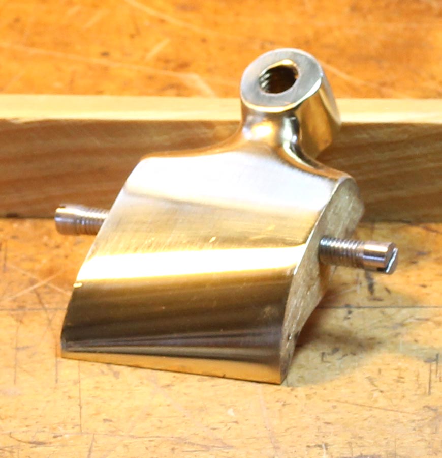
For this plane, I chose to mount the lever-cap square to the body axis. To have the toe contact the cap-iron evenly, the toe had to be both skewed & rotated to the left. It required some careful setting-out, but making the LC wasn’t all that difficult for this narrow plane. I got it close enough that it required only a little adjustment after mounting in the plane to get a good snug fit across the cap-iron.
5square LC.jpg


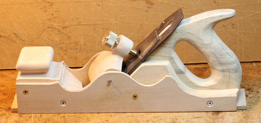
But I could see that it was going to be much more challenging to do this on a larger LC. It would need a very thick block of brass to begin with, and a lot of material would need to be removed on the underside to form the necessary rotation of the toe. On all of the old skewed infills I’ve seen, the LC was mounted parallel with the blade-bed rather than square to the long axis of the plane. This simplifies making the LC itself, the toe still needs to be skewed, but doesn’t need to be rotated. The sides of the LC are angled so they are snug with the plane sides when the LC is sitting on the blade bed. Making the LC is thus more straightforward, BUT, it needs to be mounted so that the toe remains parallel with the bed when the LC is rotated. This requires a skewed axle. It’s hard to explain & difficult to see the relationships precisely in the mind’s eye, but I needed to get my head around it thoroughly, so I made a full-scale wooden mock-up to try & sort it out:
6 PP full scale model.jpg


After one failed attempt, I managed to get the correct angles for the LC axle and get a clear picture of how it should be on the real thing. I went to more trouble making the model than needed to just fit the LC, but I also wanted to test the lines & proportion at full scale. It’s no paradigm of model-making, but it gave me the information I was after.

With a little juggling of bumps & dips on my side profiles, I managed to get both sides fitting very cosily within the 300 x 100mm rectangle:
7 Side patterns.jpg


Looks like I’ve got the green light to proceed….
 

Attachments

  • 1 pp.jpg
    1 pp.jpg
    105.1 KB · Views: 529
  • 2 C385  vs H62 b.jpg
    2 C385 vs H62 b.jpg
    127.5 KB · Views: 528
  • 3 Mockup PP a.jpg
    3 Mockup PP a.jpg
    116.3 KB · Views: 526
  • 4a.jpg
    4a.jpg
    172.3 KB · Views: 548
  • 4b.jpg
    4b.jpg
    160.2 KB · Views: 548
  • 5square LC.jpg
    5square LC.jpg
    110.3 KB · Views: 527
  • 6 PP full scale model.jpg
    6 PP full scale model.jpg
    83.8 KB · Views: 546
  • 7 Side patterns.jpg
    7 Side patterns.jpg
    70 KB · Views: 527
The necessary bits & pieces of metal were finally mustered & ready for action:
8 All bits.jpg


I’m basing this plane around a 2 3/8” Bailey type (#5.5 to #7) blade. The 75 x 5mm gauge-plate for the sole is exactly the width I calculated I need, minimising waste. The cap-iron was made up from some 3mm stainless steel left over from another project (see later on forming it); the LC is still a lifeless lump of ¾” brass; and the piece of 10mm mild steel on the right is the partially prepared blade block.

I traced my side templates on the chunk of 4mm brass, took a few deep breaths & started sawing. My saw frame is only 125mm deep, but I reckoned I could reach the centre by first sawing out the large wedges of waste at the front & back (as shown in the pic of the templates snuggled together) to let the frame in far enough. It went sort-of according to plan, but not as easily as I imagined. I had run out of #8 blades, & all I had left were #4s, which are really too fine for cutting 4mm thick material. Besides being painfully slow, they are less robust & I broke several blades trying to get at that last little bit in the centre because I couldn’t twist the saw enough in the gaps to go round the last curve. I was putting far too much side-pressure on the blade trying to force it to follow the lines and broke several several before I eventually got the sides apart:
9 Sides cut out.jpg


At this point I paused & scoured the local suppliers for some coarser blades, but there seems to be a country-wide shortage of the bigger sizes at present, & I had to settle for #6, of an unknown brand, that certainly aren’t up to the quality of the Glardons I normally buy. However, they worked ok in the brass, and so the dovetails were laid out & sawn without drama. I use a trick I got from someone on this forum (can’t remember who it was) to level the sockets, which is to clamp the side behind a straight, square piece of hard wood, carefully aligning the scribe line at the bottoms of the sockets with the surface of the wood. This makes it a doddle to file the bottoms of the sockets square and in line. You file away, keeping the file parallel with the wood until it just grazes the wood evenly (note faint file marks on the wood in front of each socket). The bottoms of the sockets should then be both square & straight:
10 sockets levelled.jpg


The completed tails were scribed on the sole, and the waste removed, but with a lot more hassle. My method for removing waste between pins is to make the “vertical” cuts with a hacksaw, then slip the jewellers saw in & cut along the scribe lines. I’ve found this (usually!) much quicker & neater than hacksawing a series of fillets & breaking them out, it leaves a much neater surface & far less filing is required. However, with these not-so-premium blades, the set quickly wore off the teeth in steel. By about 10-12mm of cutting they started to bind, and soon jammed tightly in the kerf if I persisted. I broke a blade on almost every socket.
But with persistence, a dozen or more blades, & a few involuntary expletives, I slowly gnawed them out & eventually I had them all cut, dressed, & matching neatly with their corresponding tails:
11 good fit.jpg


The last step is to form small bevels on each side of the tails. I used a bevel about .5mm wide & .8mm deep. That’s plenty enough to form a very solid lock, I’ve found. Making the bevels larger or deeper might make each joint a bit stronger, but will give you a lot more work filling them in! On old Spiers planes, instead of a bevel, the makers filed notches in the corners of the pins & tails, These form the main “lock” and the technique reduces the total amount of peening required compared with a full-width bevel. This is a useful trick for an all-steel plane, but would produce wonky-looking edges on your dovetails on a mixed-metal plane like this. Bevelling the whole side of the tail means a little more work peening, perhaps, but gives a neater result when filed off after the peening is completed.

With tails & pins fitting, the next task was to form the mouth & fit a blade block. This would be much more difficult to do once the sides are attached. My not-too-flash drill press has a bit more runout than desirable, which abetted by a slightly worn drill makes drilling 5 or 6 holes through 10mm of blade block & 5mm of sole with the required degree of accuracy a challenge. My method is to first bevel the blade block to “very close”, then rough-form the mouth and attach the blade block, aligning it with the scribe-line for the back of the mouth bevel on the sole as closely as I can. I then file the bevel in the sole to it, using the bevel of the blade block as a guide. That all went according to plan but took a lot of filing for the large mouth & deep block.
13 Mouth forming.jpg


Normally, I would use the jeweller’s saw to cut away a section of the waste for the bevel on the sole, then get a hacksaw in & cut the rest. This saves a LOT of filing. But the blades I had were hopeless & just couldn’t cope with the deeper, angled cuts in the steel. I managed to get enough out to get the hacksaw blade in but it was not straight & I almost over-cut the bevel & had to re-start the cut. The result was very messy & although I’d gotten rid of more than half the waste, there was still a lot of metal to be filed away.

The old infills usually had very thick blades (~5mm) which needed a large mouth slot & that gave the makers plenty of room for a file when forming the sole bevel. But modern blades that are slotted & suitable for use with a cap-iron are only about 3mm thick, which is roughly the thickness of a 6 inch flat file. You can get it through the starting slot, but you can’t tilt the file down enough to file the back of the bevel without hitting the front of the mouth, which would cause a too-wide mouth gap. Fortunately, there is a class of file called “warding” files. A 6 inch warding file is about 2.25mm thick & these will fit through a 3mm slot with enough play that you can angle it down sufficiently to start forming the bevel without hitting the front of the mouth (compare the warding file on left, with a 6 inch flat file on the right):
12 Files cf.jpg


Even with the coarsest cut of warding file, it takes a lot of filing to form a large bevel. Also, because the file is so thin, it bends slightly under hand-pressure and you can too easily form a rounded bevel. To prevent this, I switch to a regular 6 inch flat file as soon as there’s enough room for it, and use a combination of straight filing & draw-filing to keep the bevel flat & straight. About the time my arms were ready to drop off, the job was done, & the body is ready to go together:
14 ready to peen.jpg


Note the rivets that secure the blade block have only been roughly levelled on the sole side, they’ll be properly dealt-with when the dovetails are filed flush after peening.

***
 

Attachments

  • 8 All bits.jpg
    8 All bits.jpg
    101.6 KB · Views: 525
  • 9 Sides cut out.jpg
    9 Sides cut out.jpg
    84.6 KB · Views: 524
  • 10 sockets levelled.jpg
    10 sockets levelled.jpg
    87 KB · Views: 539
  • 11 good fit.jpg
    11 good fit.jpg
    120 KB · Views: 524
  • 12 Files cf.jpg
    12 Files cf.jpg
    94.7 KB · Views: 521
  • 13 Mouth forming.jpg
    13 Mouth forming.jpg
    100 KB · Views: 520
  • 14 ready to peen.jpg
    14 ready to peen.jpg
    86 KB · Views: 521
Nice - nice file work on the bevels, good handle proportions and an excellent handle angle.

Should be a nice user, and the reward in making is just that - making something nice enough that you'll prefer to use it.

Now that you've mastered skews, you owe yourself a rectangular shooting plane bedded at 40 degrees or so with a stout single bevel down iron. Purpose built only for that. The result will be better than anything you can buy.
 
I have a tip for those gaps as you're filing the sides of the plane to remove the dovetail waste (or however you do it).

You may not ever need the tip,and it may make more sense to solder or fill them, but I've not done that.

As the plane body is getting close to sized and most of the waste is gone, you can see those gaps appearing and tell which ones aren't going to close(as in, the ones below the level of the surface). You can lightly pein (very lightly, so you can do it accurately) just the tiny gaps and then file off the sides of the body further until the very light peining marks are gone. If you aren't chasing a myriad of gaps at different depths on other dovetails, they will remain clean (and if another one or two shows up, you can do the same trick with them until they're all gone).

Thanks for sharing your work, by the way. As we've seen in some threads that I've started, threads of actual work often garner less attention (especially if you do a good job) than posts about something like the latest blog guru's grocery store purchase. This forum is actually better than most, though.
 
Fantastic work! thanks for sharing it.
Getting the skew on the lever cap right looks like a total head scratcher, the wooden mock up looks like it was invaluable for this stage.

Thanks for the tip of filing the dovetail sockets too, I shall give this a try next time.

You talk of using a jeweller’s saw to cut away the waste. I had always though jeweller's saws where for cutting very thin parts in softer metals.
Is there a jeweller's saw and blade that would cut say 6mm mild/tool steel, as you say this would cut a lot of work sawing vertical lines and knocking out the waste with a punch.

Great work.
Looking forward to your next update.
 
MikeG.":17iqyutn said:
IWW":17iqyutn said:
....... I made it as a “half” rebate plane, i.e., with the blade parallel to the sides & extending out on the right side only.….

Why?

Obvious question I guess, Mike. :)
Like many of my projects, it started as a different plan. It was just going to be a small smoother to use up some scraps of brass & steel left over from another project, but then I decided to make it a dress rehearsal for the badger plane that was still a fuzzy image in my head. Because the blade I had was a rebate blade, I used it that way, but why only bring it out on one side? My reasoning was a) I never (well, almost never) use the left side of any rebate plane I have, and b) I reckoned only opening one side would keep the body stiffer. If I find I desperately need a left-sided rebate, well, I'll just have to make a mirror image..... :wink:

D_W - a dedicated shooting plane has been in the planning stage for at least 20 years! I have got as far as obtaining the "stout blade", but there the project has languished for many a year. Part of the problem is that I can't decide on which way to go. The favoured plan is a skewed, bevel-up configuration, but a bevel-down design something like you describe is also under consideration.

The other, & probably principal reason nothing is happening is that I so rarely use a shooting board nowadays. I do prefer using hand tools whenever & wherever they do an efficient job, but a top-tier cutoff blade and a good sliding table produce square ends as good as any I can shoot.

But making the plane is, as you suggest, an end in itself, so if I live long enough, it may eventually happen........
Cheers,
 
Hattori-Hanzo":ycv5a6ag said:
.......Getting the skew on the lever cap right looks like a total head scratcher, the wooden mock up looks like it was invaluable for this stage.......

Dead right on both counts, Hattori. :)
But the geometry is much easier when you work with a 3D object!

Hattori-Hanzo":ycv5a6ag said:
.......You talk of using a jeweller’s saw to cut away the waste. I had always though jeweller's saws where for cutting very thin parts in softer metals.
Is there a jeweller's saw and blade that would cut say 6mm mild/tool steel, as you say this would cut a lot of work sawing vertical lines and knocking out the waste with a punch.....

Well, a decent-quality #8 blade (Glardon Vallorbe or Pikes for e.g.) will cut 6mm steel with relative ease, and indeed it is both easier & neater than sawing a bunch of fillets & twisting them out. I did have to resort to that method for the centre sockets because my saw frame is only 125mm deep.
centre waste a.jpg


But as you can see, it leaves a rather ugly socket, which requires much more remedial work than the sawn sockets beside it:
centre waste b.jpg


I haven't used one myself, but I imagine those (very expensive) ladder-backed fretsaws would be the bees' knees for plane making and much nicer to use than my very inexpensive and clumsy frame. ...
Cheers,
Ian
 

Attachments

  • centre waste a.jpg
    centre waste a.jpg
    79.7 KB · Views: 401
  • centre waste b.jpg
    centre waste b.jpg
    92.6 KB · Views: 418
Right then, on to the next bit:
I made a “peening block” from scrap hardwood to hold everything in place & keep the sides square to the sole while I bash away at those pins & tails. For my first few planes I made elaborate peening blocks with cut-outs for the sides to support them when hammering down on the tails. It takes a lot of extra work to make these because the cut-outs need to be made very accurately or they won’t serve their purpose.

It’s far easier to make a simple block matching the internal shape & dimensions. The sides rest on bolts which clamp them firmly to the block & this seems to work just as well or better. I used 5 bolts to hold this plane, but 3 or 4 bolts can hold small to medium-sized planes securely enough. The scrap bits are shims to level the washers:
15 Peening clamped up.jpg


When bashing away at the pins, I rest the opposite side on a heavy chunk of steel sitting on the bench top. I don’t have a proper anvil, unfortunately, but that would be the ideal backstop.
I apply a couple of clamps to pull the sole against the sides and begin peening the pins of the sole at their inner corners, in the belief this helps to pull sides & sole together. (Some people peen the tails first, to drive the pieces together but I worry this may push the tails out of the sockets if I do that first). The clamps may need to be moved a few times until all of the pins have been peened enough to lock the joints firmly, then you can dispense with them & have a clear go for the rest of the job.

On a big plane like this, a lot of hammering is required. The real work is in peening the (steel) pins over the tails. The soft brass I used made peening the tops of the tails a breeze. After a while, my arm starts to tire, & I begin losing accuracy, so if I start mis-hitting I take a break for a while. I’ve seen various recommendations like sticking gaffer tape around the joints, or placing steel shims beside them, but neither is foolproof. You need to be able to clearly see what you are doing, so you can watch the gaps closing and keep moving the metal appropriately, so you can’t have anything too close to the edges. The best solution, I think, is to practice hammering ‘til you can strike accurately & consistently. Because you need to strike at a slight angle in the direction you want to move the metal, an occasional slip is inevitable, but that should only leave a small mark, which will file or sand out during clean-up. A full-on miss striking the brass is another matter, it may leave a dish that is too deep to get out, so do try to avoid that. When it looks like the peening is done, I like to put it aside for a while & take a long break. As it happened, it was time to pack up for the night anyway.

On close inspection next morning, I found I a couple of pins that looked a bit suspect, so I gave those & anything else that looked a bit light a good going-over. I forgot to take a picture of the completed peening, but this is what it looked like after the ends of the tails were filed flush to the sole:
16 bottom smoothed.jpg


I’ve had a bit of peening practice over the last few years, and the steel pins look a lot neater after peening than they did on my first few attempts! But peening doesn’t have to be neat, just thorough, it all cleans up amazingly well at the end, so don’t despair if your first attempts at peening look a lot more rugged than this.

Levelling the brass is easy, but the steel pins offer a more serious work-out. After making quite a few planes I've got a fair idea of the minimum amount of steel to have protruding in order to comfortably fill the gaps and minimise filing at clean-up time, but I'm still left with a goodly amount of excess metal. Even with a 10 inch turnip-cut file, you file & file, watching the lumps of protruding steel diminish at the rate laundry dries on a drizzly day. And you need to pay attention to what you’re doing to avoid grazing the brass; a coarse file will leave very deep score marks in brass. When I get the pins close to level, I switch to a 10 inch smooth-cut, and finish with careful draw-filing I try to keep the file contacting steel at all times, if it meets the brass too soon, it may create depressions between the pins. Eventually, the pins are all level:
17 Peened &  cleaned.jpg


As you can see in the pic., rolled brass plate is not dead-flat, but those dips are very shallow and will sand out easily enough at the final clean-up. There is no need to take it further yet, because riveting in the woodwork usually adds more minute depressions so it is best to do the final cleaning-up after that step.

This is the moment of truth, when you see just how well you’ve closed those dovetails. I’m pleased to report the H62 brass was delightful stuff to peen, and made that part of the task easy. Steel puts up a lot more resistance to being beaten about, and when I first used gauge-plate for a sole, I was afraid it might work-harden under the hammer, but it peens well and remains soft enough to file easily. It actually files a bit better than mild steel; the file tends to drag out large crumbs of metal which lodge in the teeth and can cause nasty deep scores across the work, but the gauge plate seems to be a little better behaved in that regard & while small crumbs do break away, they do so to a far less extent than with any mild steel I’ve used.

The body is ready for its stuffing....
 

Attachments

  • 15 Peening clamped up.jpg
    15 Peening clamped up.jpg
    104.6 KB · Views: 570
  • 16 bottom smoothed.jpg
    16 bottom smoothed.jpg
    68.2 KB · Views: 417
  • 17 Peened &  cleaned.jpg
    17 Peened & cleaned.jpg
    78.4 KB · Views: 398
Before starting on the woodwork, I spent some time filing & sanding the tops of the sides, making chamfers & some lamb’s tongues with files, then smoothing them with various grades of W&D wrapped round paddles and bits of dowel & several grades of W&D to tidy them up. This was followed by some buffing with green compound. The body is now ready for its stuffing:
18 Tops chamfered & polished.jpg


For the stuffing, I have a block of so-called “Queen” Ebony. This wood (Xanthostemon melanoxylon) comes from the Solomon Islands (& is also marketed as “Solomon Islands Ebony”) & is supposedly sustainably harvested. It is an extremely dense, fine grained wood (ADD ~1.2), but not super hard to work with. It reminds me a lot of Macassar ebony (which is a Diospyros & a “true” ebony). The colour of Queen Ebony varies a bit; this lot was quite dark on the surfaces that had been exposed during drying, but a deep brown with blackish streaks on the freshly-cut surface. I hope it will end up quite a bit darker as it ages, but it’s quite ok as-is. There are no evident growth rings, but narrow bands of alternating darker& paler wood give it some figure, which I expect will fade as the exposed surfaces darken.

The rear stuffing is made up from 3 pieces; the centre part that includes the handle, plus two cheek pieces. The handle was shaped and finish-sanded, as were the tops of the side cheeks because this is much easier to do while the bits are separate:
19 Stuffing ready to glue.jpg


I cut the blade bed slope on all 3 pieces as accurately as I could, but left a mm or so of extra wood above the scribe-lines for planing & refining the slope after glue-up, to align with the sole & blade-block.
I sanded all the mating surfaces to ensure they were clean & fresh, mixed a batch of Araldite, & carefully spread the glue inside the body & on the wood, and clamped it up. I have a love/hate relationship with Araldite. I like it for its strength and gap-filling properties but it has to be the messiest damn stuff ever created. Worse, it has no tack whatsoever, so the pieces slide around like greased banana skins while I’m trying to get the clamps on. To add insult to injury, I always mix far more than the job requires so with that, & the copious squeeze-out, about 50% of every pack ends up as waste, which is really annoying given the cost of the stuff!

Using hands, feet & teeth & some strong language, I got the 3 bits together, clamped firmly, and still aligned. =D> I cleaned up as much squeeze-out as I could with a spirits-soaked rag, checked it again (twice) over the next ½ hour while I did a few other little jobs & cleaned up for the day, then tippy-toed out of the shed & turned off the lights….
20 Stuffing glued.jpg


Next morning, I was relieved to see nothing had moved after I’d turned my back. I’d also allowed about a mm extra on each side to give me plenty of spare wood to plane down to a tight fit. I wish I’d cut it a bit closer, taking those couple of mm off was still a good workout! This wood isn’t glass-hard like some of our dry-country species, but dulls edges quickly. I found my couple of PM-V11 blades a godsend, but even they needed a touch-up before the job was done. The glued-up stuffing is also awkward to hold – my solution is to hook it with a bench-dog through the finger hole, & clamp the grip over a spacer. That held it still while I attacked it:
21 Stuffing-fitting.jpg


Next job was to cut out a slot in the blade-bed for the cap-iron screw – I tried drilling a shallow 19mm hole with a Forstner bit in my battery drill, but even with a pilot-hole, I was making glacial progress into the end-grain, so I jury-rigged a holder & finished it on the drill press. Then I chiselled a ramp to the hole to allow the blade assembly to be slid in & out easily.

A final tidy-up of the visible surfaces and a quick coat of shellac to help ward off glue squeeze-out, and the stuffing is ready to install:
22 Stuffing ready to fix.jpg


I installed the rear stuffing first so I can fit the lever cap without the front bun getting in the way.
I mixed up a big batch of Araldite, smeared it over the wood & inside the body, slid the stuffing in carefully, checked that the blade bed & blade block were aligned, and lightly clamped it. The squeeze-out was again removed with metho-soaked rags. I let it sit for 10 minutes, made a final check that everything was in place, and left it to cure….

After the glue was sufficiently cured, I fitted the LC. I was so keyed-up about it, & concentrating so hard on what I was doing, I forgot to take a single picture, I’m afraid. But briefly, I took the simplest route I could think of. I figured out where the axle hole had to be on one side of the plane, then drilled this through using a battery drill, lining up the drill bit by eye so it pointed at where I’d estimated the hole should be on the opposite side. With the first hole through, I put the LC in and pushed the drill bit through to the other side. Holding everything firmly in the correct position against the blade assembly, I drilled the hole on the opposite side. A somewhat crude bit of engineering, but both screws went into the LC perfectly, and it tightened squarely on the cap iron. (Insert big sigh of relief here!)
 

Attachments

  • 18 Tops chamfered & polished.jpg
    18 Tops chamfered & polished.jpg
    92.6 KB · Views: 393
  • 19 Stuffing ready to glue.jpg
    19 Stuffing ready to glue.jpg
    112.7 KB · Views: 438
  • 20 Stuffing glued.jpg
    20 Stuffing glued.jpg
    112.4 KB · Views: 415
  • 21 Stuffing-fitting.jpg
    21 Stuffing-fitting.jpg
    117.5 KB · Views: 393
  • 22 Stuffing ready to fix.jpg
    22 Stuffing ready to fix.jpg
    128.7 KB · Views: 394
I forgot to cover this part of the metal work, so fwiw, here is a quick run-down.

Judging by what I’ve read in various threads on making planes, many aspiring makers are intimidated by the idea of making lever caps, imagining it to be a very difficult task. In fact, it’s one of the easier (& fun) parts of the metalwork, particularly for an uncomplicated plane. Brass is easy to saw & file, and seeing a shapely cap slowly emerge from a plain lump of metal is very satisfying. Provided you work with a little care, using a template or two & layout lines wherever possible, it’s all pretty straightforward. The critical part is getting the axle (pivot) hole accurate so the toe makes even contact across the cap-iron, which is not especially difficult (at least for a ‘normal’ straight blade setup). Even if you get the axle slightly off, you can file the toe a little to get good contact. One advantage of using screws rather than a rivet for the axle as I like to do, makes it easy to take the LC out as many times as necessary when setting it up in the body.

This LC is not quite so straightforward due to the skewed blade. I spent a good bit of time thinking about it and how best to make & fit it. On the skewed planes I've made previously, I mounted the LC ‘square’ in the body, which necessitated skewing the toe to a compound angle. That wasn't too hard because those LCs were narrow, & the total amount of ‘twisting’ of the toe was relatively small. For this plane, I decided to go with what seems to be the conventional approach, which is to install the lever-cap so it is parallel with the skewed bed, and skewed to the axis of the plane. This simplifies making the lever cap a little, the toe end needs to be skewed, but not twisted. It does, however, complicate fitting it in the body. We’ll get to that part in due course.

First, with hacksaw & files, I cut the sides to the required angle for it to sit parallel to the blade bed Then I drilled & tapped for the thumbscrew, rough-formed the cove underneath the toe, and finally cut out the shoulders around the thumbscrew. The lump of metal starts to morph into a lever-cap:
23 LC1.jpg


While it still had substantial flats top & bottom to hold in the drill-press vise, I set out & drilled the axle hole. I didn’t trust a long bit to go through accurately in one go, so I set up very carefully, & drilled from each side with a short 4.2mm bit. Happily, the holes met nicely in the centre. I tapped a 5mm thread into each side about 15mm deep, for the axle screws. If I decide to use a rivet instead, I’ll need to enlarge the axle hole to a clean 5mm, but I’ll see how I go with plan A. The axle is skewed to the axis of the LC (it follows the pencil line, which looks close to square in the picture because of the perspective, but it’s about 10 degrees off square):
23 LC 2.jpg


From here on, it’s just a matter of refining the shape with round & flat files and sandpaper wrapped around dowels or sanding blocks until it looks as much like a lever-cap as I can make it. Here it’s been finished to 400 grit, but I will probably need to make some small adjustments to the toe after it’s mounted in the plane, so I’ll leave it there for now:
24 LC 3.jpg


The cap-iron
Making a cap-iron for a skewed blade is a bit more challenging than for a straight blade, but not that much. I stared with a scrap of 3mm thick stainless-steel.

To put the required bends in my cap-iron, I hauled out the Heath-Robinson bending jig, made for my first infill. It required lots of gaffer tape to hold the blank at the correct angle for the skew and more tape to keep the dolly in position while I got it all into the vise:
25 bending c-i.jpg


The first bend came out very well and I was feeling quite smug until I realised I’d put the darn thing in upside-down & made the curve on the wrong side! #-o Fortunately, the blank was much longer than needed, so I cut off my mistake & (more carefully) went through the motions again, this time laying it on the jig to get the curve the correct way relative to the toe.

I ran the inside of the curve over the grinder using a simple holding jig to neaten the curve & thin it down a little, then set it up on the bending jig again & made the second (reversed) bend with no further dramas.
26 bending.jpg


The outer curve was filed smooth and tapered to a clean, sharp edge to mate with the blade, then the top tidied up & chamfered. Finally, the entire outer surface was sanded to 1200 grit. It’s now beginning to look like a proper cap-iron (with a twist), it just needs a hole drilled & tapped for the screw:
27 CI sanded.jpg


All ready for the home straight....
 

Attachments

  • 23 LC1.jpg
    23 LC1.jpg
    114.8 KB · Views: 404
  • 23 LC 2.jpg
    23 LC 2.jpg
    117.1 KB · Views: 388
  • 24 LC 3.jpg
    24 LC 3.jpg
    122 KB · Views: 421
  • 25 bending c-i.jpg
    25 bending c-i.jpg
    88.6 KB · Views: 386
  • 26 bending.jpg
    26 bending.jpg
    73.9 KB · Views: 407
  • 27 CI sanded.jpg
    27 CI sanded.jpg
    76.4 KB · Views: 404
After the LC was sorted, I glued in the front bun and put brass rivets through the body to hold the stuffing. The epoxy would probably suffice, at least for a few years, but the rivets give long-term insurance. When setting the rivets, I was a bit clumsier than usual, and made a couple of over-strikes on the brass of the sides. While that soft brass was lovely to peen, it’s also easier to mark than the harder 385 brass I’ve used previously so my mis-hits left a couple of rather obvious divots. Then a bit of filing & sanding got rid of the rivet-heads. This is only rough-sanded with 120 grit, the final spit & polish will be the very last step:
28 Done.jpg


At last, I can get a sneak preview of what all that work has achieved. I put the lever-cap in, popped in the blade assembly, tightened it down (with the blade well-retracted), & lapped the sole for about 10 minutes on a 60-grit linisher belt tightly-stretched across my tablesaw top. That got the sole roughly flat, then impatience got the better of me. I took out the blade & cleaned out the swarf, then set the cap-iron about .8mm back from the edge, put it back in & set it to begin cutting. Shavings straight up!
29 First shavings.jpg


However, all wasn’t well, it started cutting erratically after a few strokes. I pulled the blade out, & as I suspected, my cap-iron wasn’t seating properly on one side, so I spent a few minutes sorting that out & tried again. This time it kept cutting & produced some decent shavings.

So as far as the build is concerned, that’ that. I still have a couple more hours work to finish it properly. The sole is far from fully lapped yet, the sides need final sanding & polishing, and I have to decide how I’m going to fix the lever cap in – obviously, I can’t leave those ugly screw heads sticking out! I’ve got a couple of ideas, so we’ll see how I go with those.

Epilogue.

I wrote the above more than a week ago, & have had some time to re-visit my new plane. I will no doubt spend more time fiddling with it to get it working to the level I expect of it, but it’s now functioning pretty well. I made a couple of “cheese-head” screws for the lever-cap & they look fine. I set them a teeny bit deeper than I would on a straight cap and you don’t really notice that the top of the head is skewed a bit relative to the side. The cap-iron needed quite a bit more work to get it to seat properly, and the lever cap also needed about 0.5 mm off one side to get full contact across the cap-iron. A bit more lapping has got the sole almost to my satisfaction, but some afternoon when I’m bored & want a mindless job I’ll have another session on it.

I’m reasonably pleased with the plane overall, it’s now performing about as well as its predecessor & I’m confident I can lick it into better shape yet, with a bit more fiddling. There are minor details I would change if doing it again, but that’s the nature of the game when every plane I’ve made was a ‘prototype’. The woodwork has come up very nicely & has a superb silky, tactile quality that invites fondling. There is a tiny crack along the side of the front bun, and another in the horn of the handle (this is a difficult wood to dry successfully in big sections!). Neither is likely to ever be a problem, but I wish they weren’t there.
30 L side.jpg


But before I leave the room, there is something I have to own up to.

When drilling one of the rivet holes, the long 4mm bit I was using wandered, and exited a good 5mm away from where it should have, right on the edge of the metal!
31 Disaster.jpg


I was aware it would be a close because of the offset sides, but I’d calculated the hole would be a comfortable distance from the edge when it came though. Instead, only about a third of the hole is in the metal. I came close to despair when it happened, but it was entirely my own fault. The drilling was very slow-going because the oily wood packed in the drill lands, choking it up & I had to withdraw the bit & clear it every few mm by the time it got to about half way though. I was getting a bit fed-up & forcing the bit further & further before clearing it, so it serves me right that it responded by going off-course.

After staring at the hole in disbelief for some minutes, I decided on a course of action to rescue the situation. I marked the point where the drill should have exited, then used a shorter, more rigid bit to try & hit the first hole. It worked, the holes met cleanly about the centre and I was able to place & set the rivet without difficulty. I then carefully scraped away at the hole in the side with an old chisel sharpened with a high bevel, until I had it tidied up. The hole in the wood was easy enough to patch semi-invisibly.
32Rt side.jpg


You can see the curve still isn’t quite right, I’ve got it smoothed, but it needs more work to fair the curve properly - another job for a rainy afternoon.

Well,a s I said in another thread, every project teaches us something. The lesson this one was trying to teach me is........ patience!
#-o
Cheers,
 

Attachments

  • 28 Done.jpg
    28 Done.jpg
    98.9 KB · Views: 353
  • 29 First shavings.jpg
    29 First shavings.jpg
    132 KB · Views: 372
  • 30 L side.jpg
    30 L side.jpg
    97.9 KB · Views: 353
  • 31 Disaster.jpg
    31 Disaster.jpg
    100.2 KB · Views: 354
  • 32Rt side.jpg
    32Rt side.jpg
    103.3 KB · Views: 354
Wonderful write up and Excellent work to boot.
Lots of helpful tips, thanks for sharing them.

Your plane looks brilliant and i bet it works a charm too.

I know to well the plight of a wandering drill bit, You've done a good job getting over the issue.
Very difficult to correct the curve now the infill is fixed in place, how are you going to approach this?

Just an idea, could you make a flat bottom drum sander the same size as the curve you want and use it in a pillar drill?
This way you can sand the brass to the right curve without touching the wooden infill.

Getting over problems is half the fun of creative working.
 
Hattori-Hanzo":2qff5que said:
.......I know to well the plight of a wandering drill bit, You've done a good job getting over the issue.
Very difficult to correct the curve now the infill is fixed in place, how are you going to approach this?

Just an idea, could you make a flat bottom drum sander the same size as the curve you want and use it in a pillar drill?
This way you can sand the brass to the right curve without touching the wooden infill.

Getting over problems is half the fun of creative working.

Thanks Hattori, yep, it's functioning pretty well now, but I think it will be a teeny bit better after I spend a bit more time lapping that huge area of sole. It's a job to tackle in small doses hen the mood strikes.

To get rid of the 1/3rd hole on the edge of the brass, I sharpened an old beater chisel I keep for such purposes with a high bevel (~40-45 deg), and used that to cut/scrape away at the brass. It needed re-sharpening every few minutes, but did a good job. By resting the back of the chisel on the high points either side of the curve, I could apply a bit of force & leverage on the edge and shave off continuous strips of metal without touching the wood. But there was a point in the centre of the curve where the chisel would chatter, no matter how carefully or lightly I shaved, and I could not get the curve to fair the way I wanted. So I decided to leave it where it is for the moment. I don't trust myself doing the job with any sort of powered tool (a small drum on a Dremel might be good, but don't have one of those). It can be done with hand tools well enough, just takes a bit longer. I decided what I need is a scraper with a bit of a 'spoon' curve so I can bring the edge to bear on the bottom at a better angle. Got too many other projects on the go atm, including some home maintenance jobs (how I detest painting!) so it will have to wait for the proverbial round tuit.

Yes, mistakes can certainly bring out the 'creative' side of us, but I'd much rather not have such stupid blunders to fix. I know the dangers of long bits wandering all too well, so I feel doubly stupid when something like that happens just because I got too impatient! #-o

Cheers,
Ian
 
Back
Top