Star point in three phase motor

UKworkshop.co.uk

Help Support UKworkshop.co.uk:

This site may earn a commission from merchant affiliate links, including eBay, Amazon, and others.

memzey

Established Member
Joined
8 Apr 2013
Messages
1,753
Reaction score
16
Location
St. Albans
Hi gang,

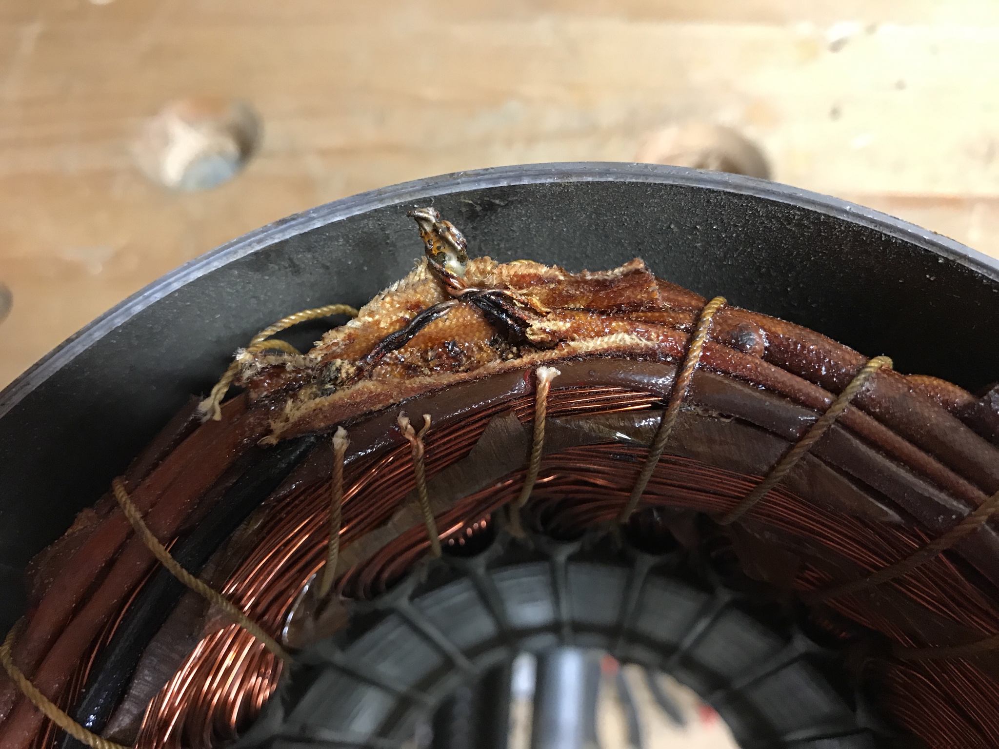
I was wondering if anyone here as any pointers on finding the internal star point on a three phase motor? I’ve opened up one that came with something I bought ages ago, hoping I could wire it delta but there is no obvious internal point where the windings come together. Is there a general place I should be looking or any other pointers on how to find it? Photos below:
Ult40oC.jpg

pa550Yr.jpg

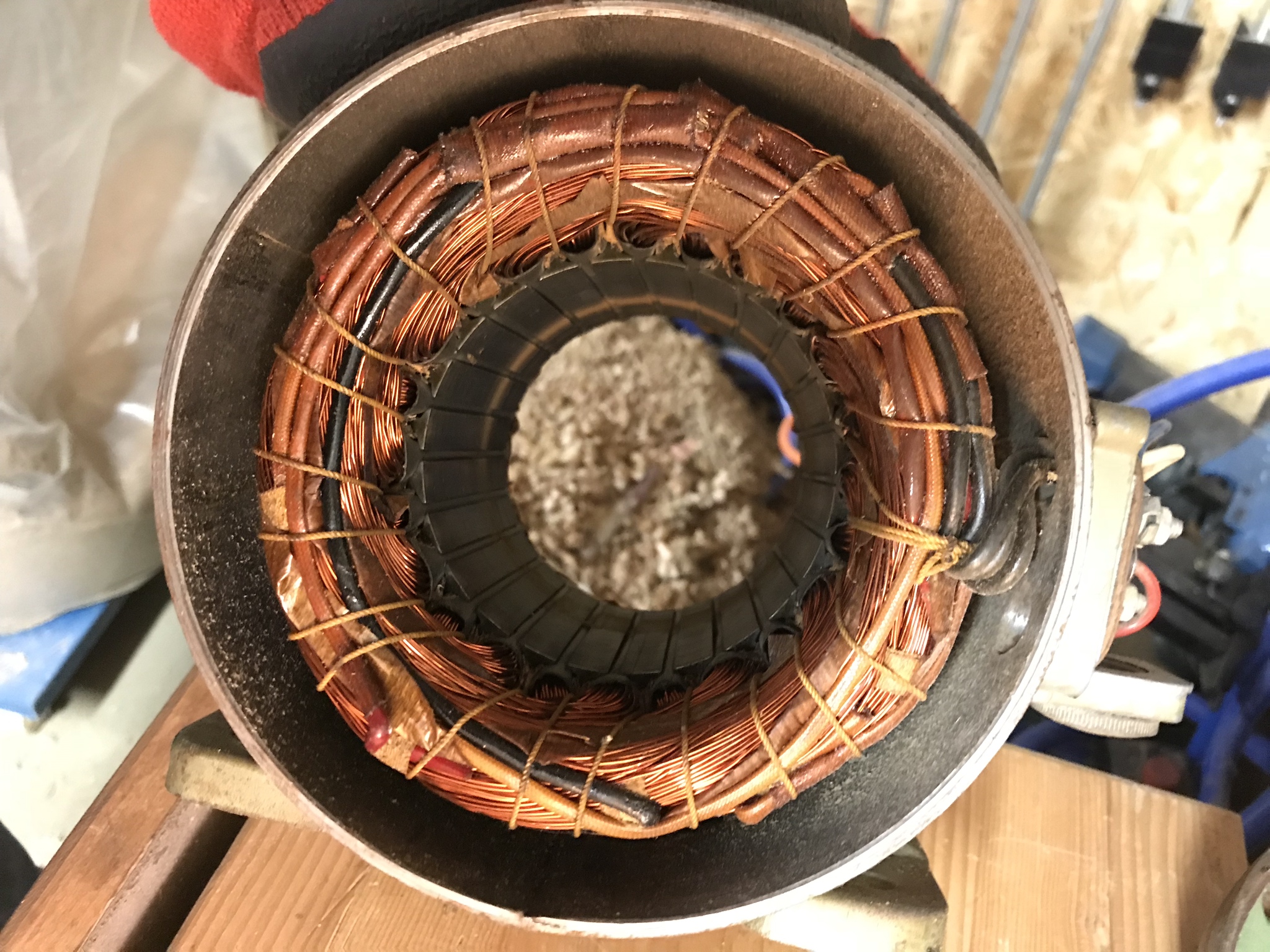
Only one end of the tails comes out into the junction box outside (415v). All help much appreciated.
 
At the end of the motor where the wires are there is a black sleeved wire under the lacing . You have to carefully cut the lacing and tease it away and then find those 3 wires joined. Solder new wires on and bring those out to the terminal box
With a meter then determine which pair are which and mark accordingly
Ian
 
The star point is shown in the last photo. There are three wires with brown sleeving on that terminate at approximately 12oclock and run adjacent to a single wire with black sleeving. The star point is almost always on the same end that the wires enter the motor.
 
I'm guessing by lacing ,you guys mean the sheath around the wires, and not the (rope/cord?)
holding the windings together...

So just a matter of gently pulling them out from under the rope/cord..
Say maybe two wraps of rope/cord, no more than three, so as not to make the wrapped windings loose..
Is there a danger of this ?


Am I right in assuming there should be only three wires ends in this location,no more wires to worry about,
and that they are usually to be found on the same end of the motor, as where the other wires go to the terminal box?

Do you keep the sheath and reuse it again to cover the solder blob, as I presume its some kind of special stuff?
Any more tips appreciated
Thanks

Keep us posted Memzey :D
Tom
 
"Lacing" is the string holding the winding in bundles.

The sheathing or sleeving often starts out as a high temperature woven tube which becomes soaked in with varnish when the windings are vacuum impregnated. It is best to use NEW high temperature sleeving NOT PVC, Silicone is OK.

The starpoint is normally brazed together to form a high temperature tolerant joint.

The older the motor the more fragile the winding insulation becomes - proceed with caution.

A good source of high temperature sleeving and wires to bring out the new connections can be obtained by stripping down immersion heater cable obtainable from the DIY sheds by the metre. The outer sleeve is not useful but the inner wires are. It would be regarded as poor practise to use the earthwire for anything other than grounding but the blue and brown are fine to use for the winding ends.

Lace back up with nylon cable ties so that no loose wires can get anywhere near the rotating parts.
 
Thanks everyone.

I had a quick poke around and opened up the area suggested. This is what I found:
6VzymIj.jpg

I’ve never seen one of these before but that would be broadly what I was expecting in as much as there are some wires connected together. Can someone with more experience confirm please?

All I need now is to learn how to use this bloody thing (too complicated by half)
tBM9yIZ.jpg
 
Cheers deema. Good to have that confirmed. Do you have any idea as to whether I can use that contraption in the second pic to test for continuity between the wires? I manage to get a reading from a battery if I touch the ends in the right way and have the connectors in the right sockets but nothing else. I suspect this probably isn’t the correct tool for testing continuity that’s all I’ve got (apart from one those little screwdrivers with the light in the handle).
 
Can a regular multimeter be used to check for continuity checks?..
or do you need to have a Megohmmeter for the job...
You might find how to use it specifically on a motor, if you google video search motor insulation tests with a megger.
I was expecting to see three thick wires...
Is it just three skinny windings bound together, it looks like it to me?

Why is a nylon cable tie OK to use, but PVC sleeving not recommended ...
Not really needing to know this, I will try and get to the point constructively instead.
I don't know if cable ties are all made out of the same material....
I suspect it would be a good laugh for the boys in the electrical shop if I were asking this :lol:

Looks like your getting there Memzey
I was looking for a clip of Dustin the turkey saying go wan ye good thing!

Thanks for posting, looking forward to more
Tom
 
And another question...
So, the starpoint is normally brazed together to form a high temperature tolerant joint.
I'm wondering if this rules out a regular soldering iron for the job?
Does one need special soldering wire?
Thanks
 
memzey":3p7ojprq said:
All I need now is to learn how to use this bloody thing (too complicated by half)
tBM9yIZ.jpg

To check for continuity, reconfigure your meter this way:

1. Plug the red lead into the "VΩA" socket.
2. Plug the black lead into "COM" socket (where the red lead is in the image).
3. Turn the black knob to the top so the white index is at the "X10" setting (about the 11 o'clock position on the dial).
4. Touch the other end of the black and red leads together and the needle should swing to the right.
5. Adjust the small wheel on the bottom of the meter, at the "0Ω ADJUST", so the needle is at zero on the top scale of the dial.

If the needle doesn't move, or you can zero it, the meter battery is likely flat and must be replaced.

Now you can check the motor windings for continuity. I don't know what the resistance should be for each of the windings.

If you want to use this meter for checking mains voltage, leave the red and black leads connected to the meter as described above, and turn the knob so the white index is at the red "600" or "300" in the "ACV" section.

When you're finished with the meter, set the knob to "600" in the "ACV" section and unplug the leads. Since this meter doesn't have an "OFF" position, the 600 Volt setting is a safe position.
 
what Mike said, but i think you would get a more accurate reading with it on X1. measuring a single copper wire should give very low numbers (almost zero) timesing by ten would distort your reading.

If you have disconnected the connection wires from each other, while its in that mode, move one probe to each of the other wires in turn. You should not get a reading across the circuits. If you do the insulation on the copper wire windings is cracked which is basically a kiss of death to the motor.

Continuity is just being able to pass a big current from one probe to the other and is like a sledgehammer being used to adjust a watch.
Resistance is the measurement of the resistance through that one circuit, which you need to measure accurately to determine if the circuit is fit for purpose.
 
That looks like a union graduate lathe motor......I could be wrong! The problem with soldering it that in a stall situation where the motor is switched in and isn’t moving is that the windings become an effective short circuit across the mains. This turns the motor into a heater, the current dramatically increases and the temperature inside increases rapidly. If nothing stops this situation the motor can catch fire. If your running the motor with a decent electronic Inverter over current protection should be built in to detect a stall. If this is the case twisting the wires together and soldering will be fine.

Don’t forget to put the thrust washer back in, it goes on the opposite to the spindle.
 
Thanks everyone - I really appreciate the help.

Bob - I made up a batch of hard wax polish for you on Sunday night. We fly on Thursday - yay! Before we go I’ll try the multimeter configured as suggested and see if I can test for continuity that way.

deema - good guess but it’s actually from a 1963 Wadkin dimension saw. It is a Brooks motor though so they probably put something similar on Graduate lathes as well no doubt. There is no thrust washer I can see at the other end - just a fan.

The reason I’m doing this by the way is to explore possibilities for running a three phase lathe (which I haven’t bought yet but hope to bring home towards the end of August) in my single phase shed. Life would be easier if the motor were dual voltage but as it is also from the 1960’s I doubt that will be the case, hence my wanting to be clear on these matters before buying. Being able to wire the motor in delta means I can avoid the need for an expensive phase converter and opens up other possibilities. I could go down the VFD route for the lathe as it’s only 1hp so cheap ones (with potentiometers for variable speed) are an option but I’m also thinking about use of a capacitor to generate the third leg and might try that with this motor to see how it would work. The biggest question I have on that front is how to calculate the uf rating requirement for the capacitor. All the literature I’ve seen on this topic either involves people with loads of capacitors laying around, swapping them out until they get the right reading or a formula that looks like Ancient Greek and makes my brain want to melt (homer).
 
Darn, no prize for me!
If your going to run it from a VFD then soldering shouldn’t be an issue. The VFD will detect the over current and shut down saving your motor and soldering. There will I’m sure be a thrust washer sitting at the back of the motor, it’s pribably stuck to the casing covered in grease.

I personally avoid unbranded Chinese VFD’s despite the very attractive price. They may or may not be good. That’s not to say they don’t appear to work. They may we’ll be unbranded product off the same production lines as a branded product, but equally could also be not designed properly. I used to run 3 factories in China a number of years ago, it made me very sceptical about most things from that part of the world without rigorous checks and balances. CE marking is often interpreted as Chinese Export which I know is a joke over here, but a reality over there!

Well made and designed VFD’s are a joy to use and install.
 
Memzey. First up good job on having a go, I Iike folks who get stuck in. I did precisely the same on the motor on my Wadkin planer. My approach, not saying it’s correct but it’s worked fine for the past three years.
- I dug out the star point then simply twisted and soldered the additional leads to take out the motor body. Used wire from an old 2.5mm flex, wrapped the joints in simple insulation tape :oops:
- cable ties were used to secure everything inside the motor, right pain to get the threaded where required
- used the multimeter to measure the resistance of each winding, and resistance winding to motor body. Showed the resistance of each winding was almost identical and saw no continuity to the motor body.
- the whole capacitor thing for a false third phase was as you said a pain to understand, so for £85 I bought a ‘CE’ VFD, mounted it inside a Tupperware for dust protection and it’s bob on.

Regards.

Fitz.
 
Ttrees":2zihqgj0 said:
Why is a nylon cable tie OK to use, but PVC sleeving not recommended ...
Not really needing to know this, I will try and get to the point constructively instead.
I don't know if cable ties are all made out of the same material....

Tom

Yes they are different materials - poly vinyl chloride and nylon
PVC wire insulation not only has a lower melting point than nylon but it also goes soft well below its melting point and the insulation is compromised.
 
sunnybob":3t7utstp said:
what Mike said, but i think you would get a more accurate reading with it on X1.

The only ranges I see for resistance are X10 and X1K (X1000). It was common for older analog meters to not have a X1 range because of the battery drain.
 
I tried what you suggested Mike and managed to identify and mark the tails from the star point.
sPojv9v.jpg

I also checked for continuity between the windings and between each winding and the motor case - there was none. All good now until I get back from holiday. I’ll see if I can read up some more on how to calculate the uf required for a capacitor while I’m away but if anyone has any hints in the meantime please do share!
 
Back
Top