Entry hall table for a niece

UKworkshop.co.uk

Help Support UKworkshop.co.uk:

This site may earn a commission from merchant affiliate links, including eBay, Amazon, and others.
Brilliant!

Some people spend a fortune to go on woodworking courses that wouldn't match Derek's WIP's.

Much appreciated as ever.
 
The legs are on. I must admit to mixed feelings at this stage. This is not my style of leg, but it is what my niece wants. Perhaps I will feel differently with a finish on the wood.

10a.jpg


2a.jpg


The tenons were kerfed for a wedge ...

3a.jpg


Installed in the bases ...

4a.jpg


5a.jpg


And glued into the socket. Note that only the first third is glued. The rear is free to move ...

6a.jpg


The bases have been shaped to reduce their impact ...

7a.jpg


11a.jpg


The legs were evened up ..

8a.jpg


Side view from underneath (one does not see the base otherwise) ...

9a.jpg


Regards from Perth

Derek
 
thetyreman":2xzrr1f9 said:
is that titebond liquid hide glue? ..

Yes .. Titebond Liquid Hide Glue. I use it on anything which may need to be taken apart, now or later, or for the open time, such as the case dovetails. For parts where there is no stress or need to adhere quickly, then I use Titebond II or III.

Regards from Perth

Derek
 
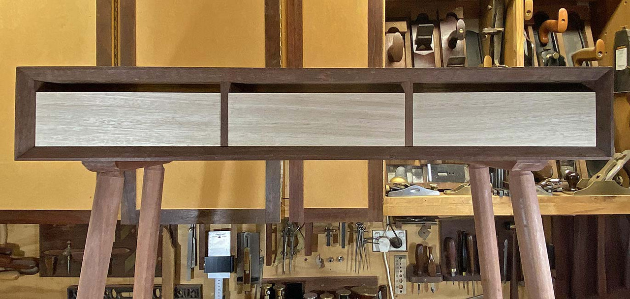
It's time for the drawers. Once again there is a challenge. The design calls for drawer fronts that stretch across the front without being broken by drawer dividers. In other words, "lipped drawers".

There are two ways to do this. The easy way is to used "planted fronts", that is, attached fronts to the front of a box ...

lipped-drawer_5F00_lead1.jpg


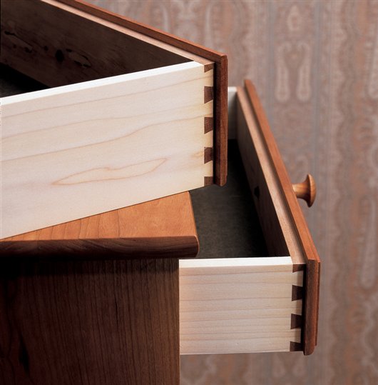
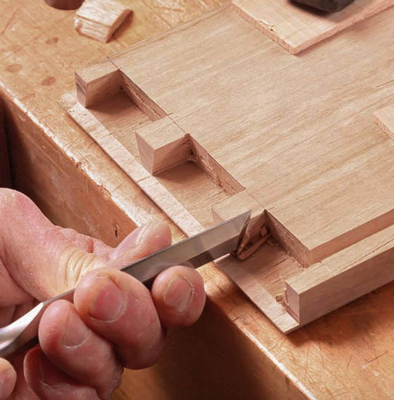
The hard way is to make the drawer front a single piece. This requires rebating the drawer front and forming a half blind dovetail in the side of the rebate. Courtesy of Christian Becksvoort ...

Lipped-dovetail2.jpg


I've chosen the high road (sigh).

Today I spent my time preparing for three drawers. Why three and not two, as in the original design? Simply because I can build them narrower, and this will make them less likely to rack. They'll end up somewhere around 280mm wide and 290mm deep. I anticipated that 375mm wide and 290mm deep would be a disaster waiting to happen. The only way drawers that dimension could work is on runners, which I do not do.

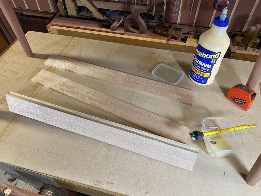
The wood for the drawer front is more Fiddleback Jarrah (by request), while the remainder of the drawer is quarter sawn Tasmanian Oak (which is actually a Eucalyptus, and is quite unstable unless quarter sawn. I keep a stock for drawers). It is a lot like US White Oak in appearance and hardness.

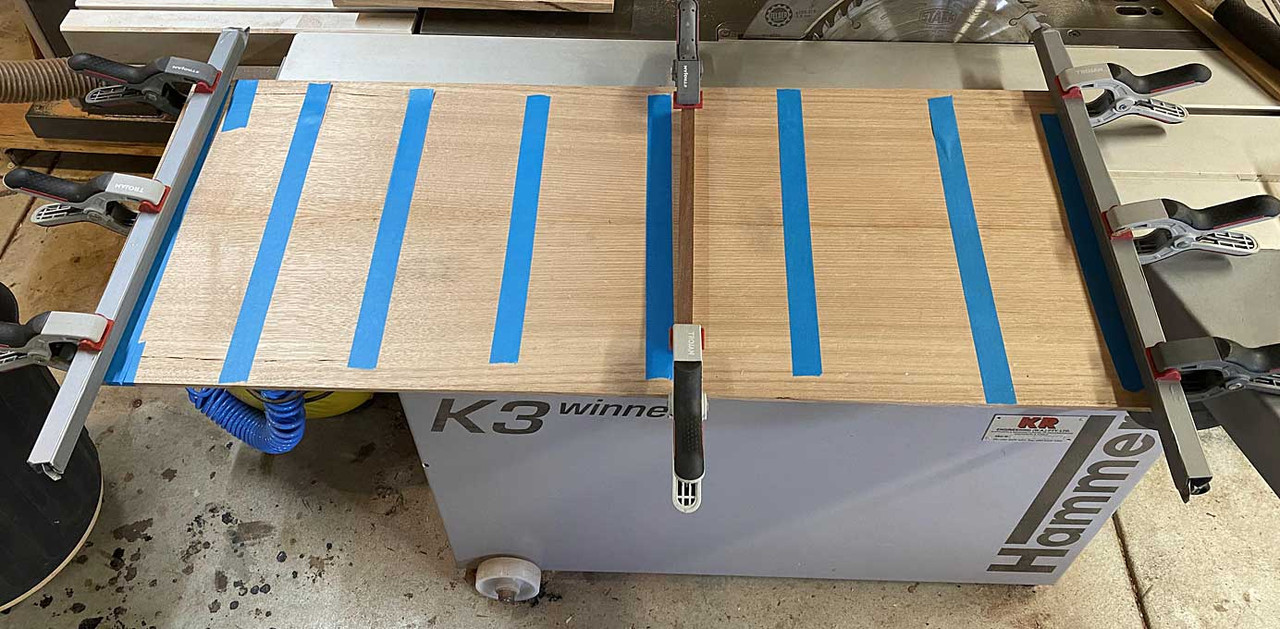
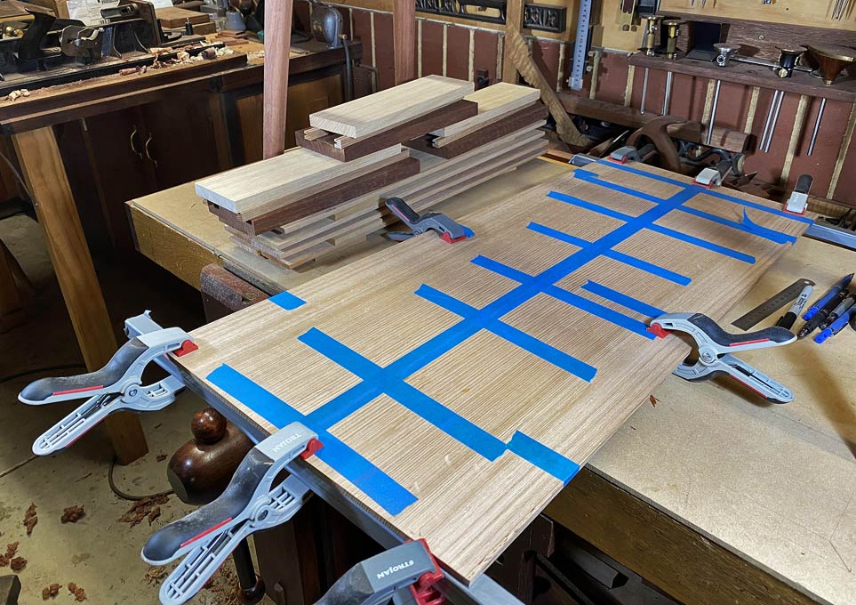
I have a bunch of narrower boards, which I re-sawed to make 7mm thick drawer sides, and glued together two to get the height needed ...

2a.jpg


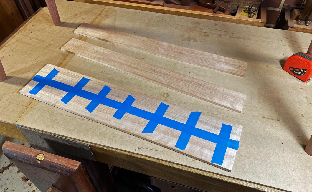
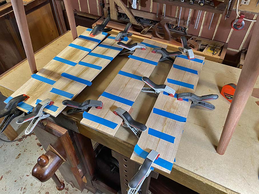
No clamps, just blue painter's tape, which is stretched across. It pulls the edges together.

1a.jpg


This is enough for 4 drawer sides (one spare) ...

3a.jpg


The drawer bottoms will be 1/4" (6.35mm) thick ..... I cannot go metric here as my plough blade is imperial :) 
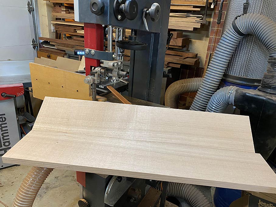
.... this is re-sawn from a wide board, which saves some effort as only two boards are needed for the bottoms (the grain runs across the drawer) ...

13a.jpg


Same trick with the blue tape, and cauls are also added to keep it flat. This will be sawn up at the time it is needed, and the panel will remain in the cauls until thn.

14a.jpg


The narrow drawer sides necessitate using drawer slips, which is a strip added to the sides with a groove for the drawer bottom. This also adds extra width as a runner.

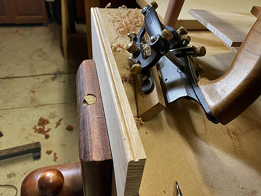
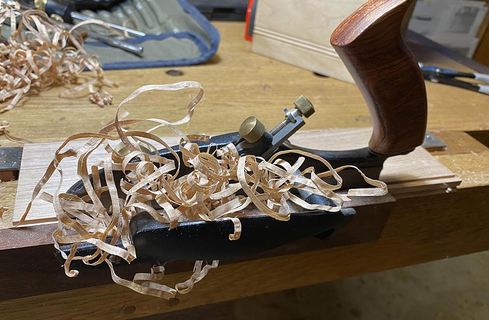
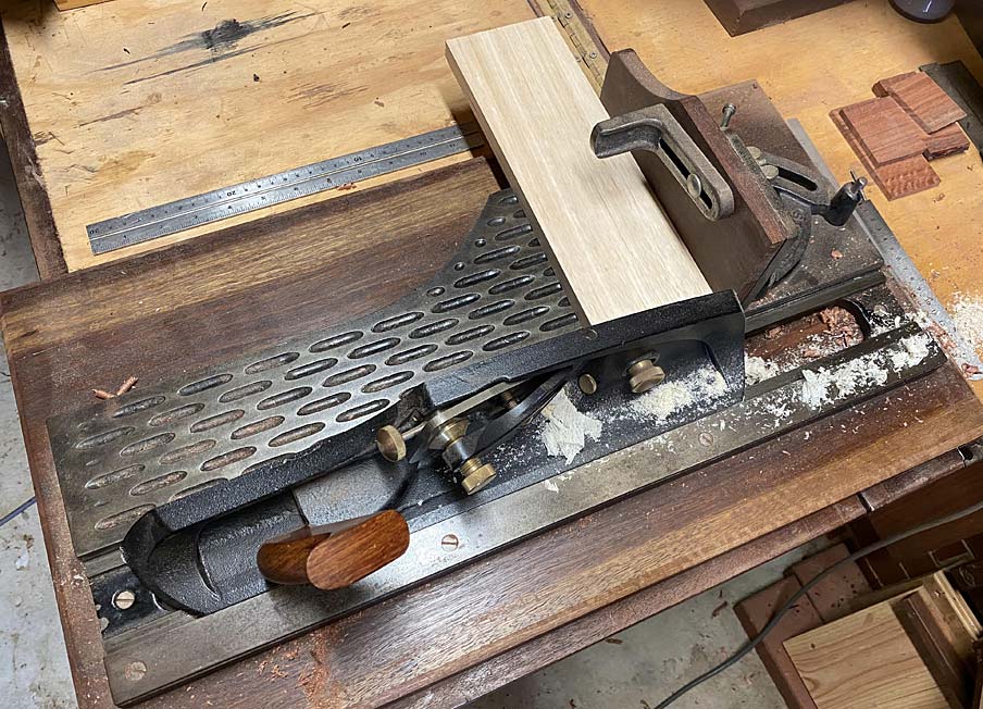
The slips are made with a plough plane. In this case, I used both a Veritas Small Plow (to plough the groove) and the Veritas Combination Plow (to plough a bead - the bead lies at the join of the slip and drawer bottom). Setting up both save time switching set ups back and forth, and once begun, making these slips was a quick process ...

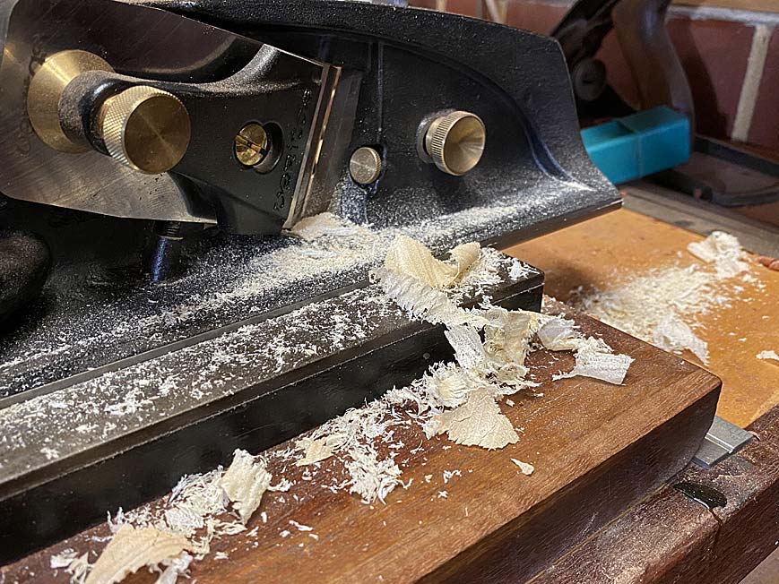
First plough the bead ...

15a.jpg


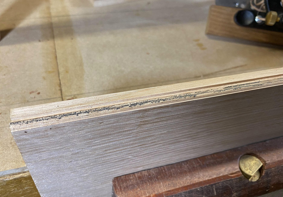
A tip on how to avoid over-planing the bead. This comes from David Charlesworth. Scribble pencil along the top of the bead, and when it is gone, the bead is complete ...

16a.jpg


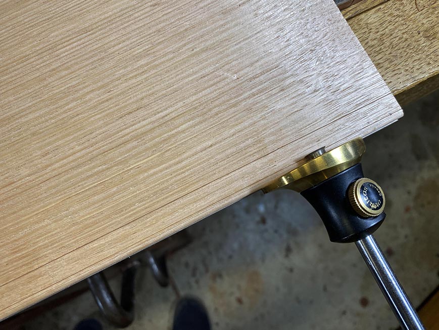
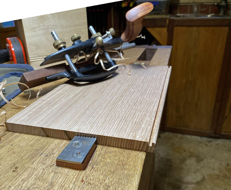
Now flip the board around to plane the groove ...

The first line is where the groove begins, which is 3mm below the bead. There will follow a 1/4" groove, and there will be 4mm below this to support the groove/drawer bottom. This makes the slip a smidgeon over 12mm high. It is 10mm deep, which allows for a 5mm deep groove.

17a.jpg


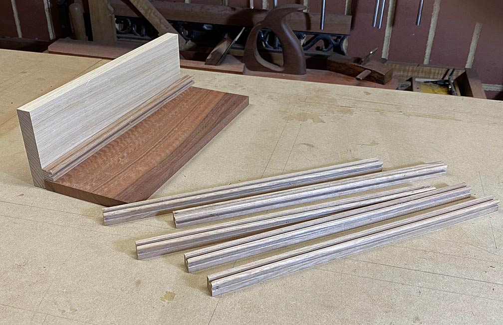
As mentioned, once set up, no further marking is necessary. Just plane ...

18a.jpg


19a.jpg


... and then rip off the slip on the table saw.

20a.jpg


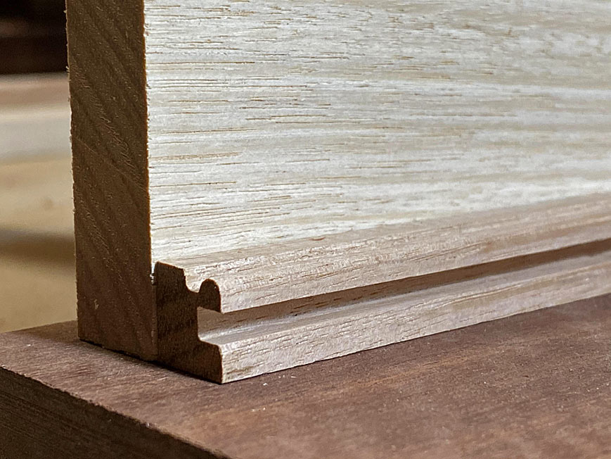
This is a mock up: the bead at the top and the groove on the side ...

23a.jpg


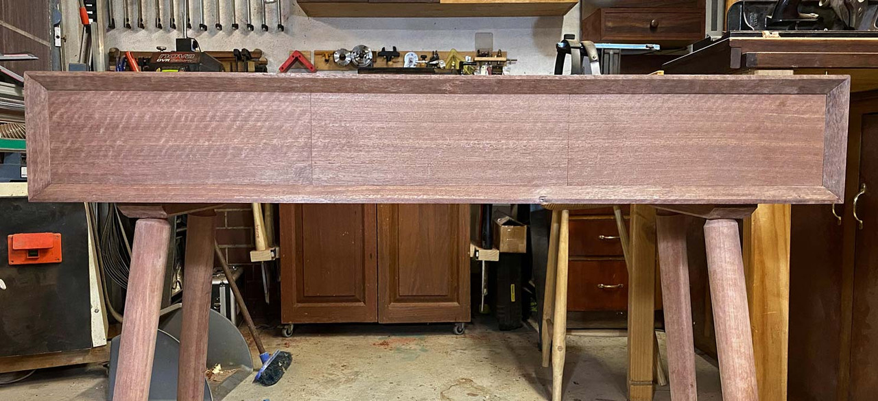
I have a strategy to fit the drawer fronts, so that the edges align with each other. It is all about accurate marking out. This will hinge on getting the opening exact, and transferring the respective measurements to their drawer fronts.

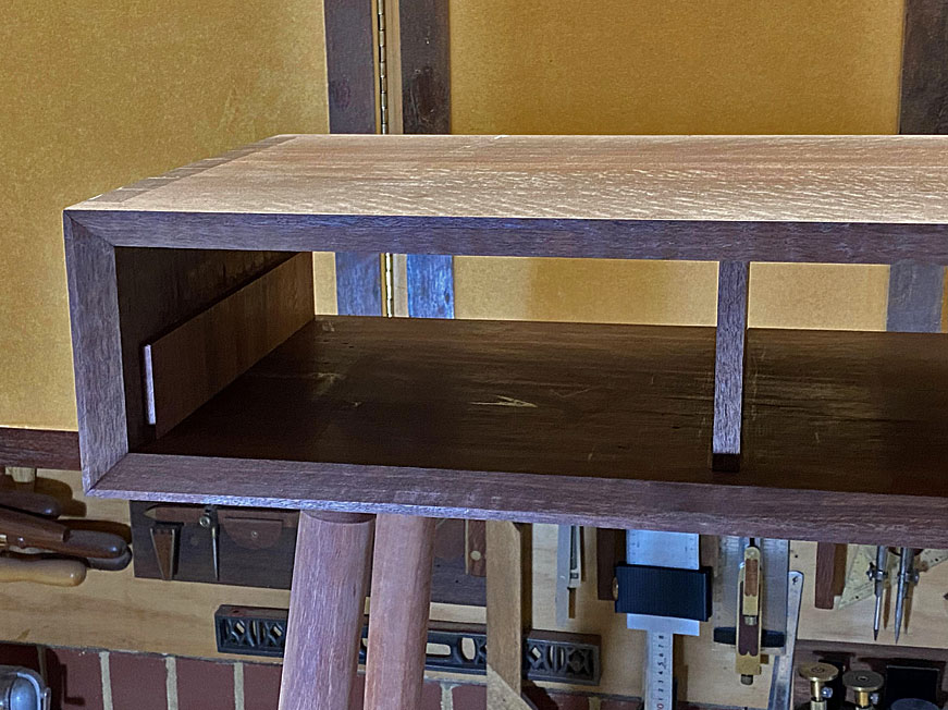
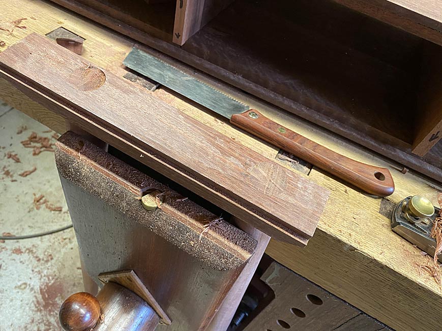
First order of the day was to fit (what will become) drawer backs to the front between the drawer dividers. This is what the result looked like ...

4a.jpg


The table saw can cross cut really close, but only a shooting board will get the final dimension ...

5a.jpg


6a.jpg


On to the all-important drawer fronts!

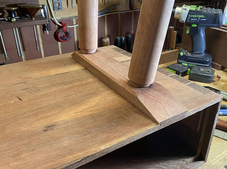
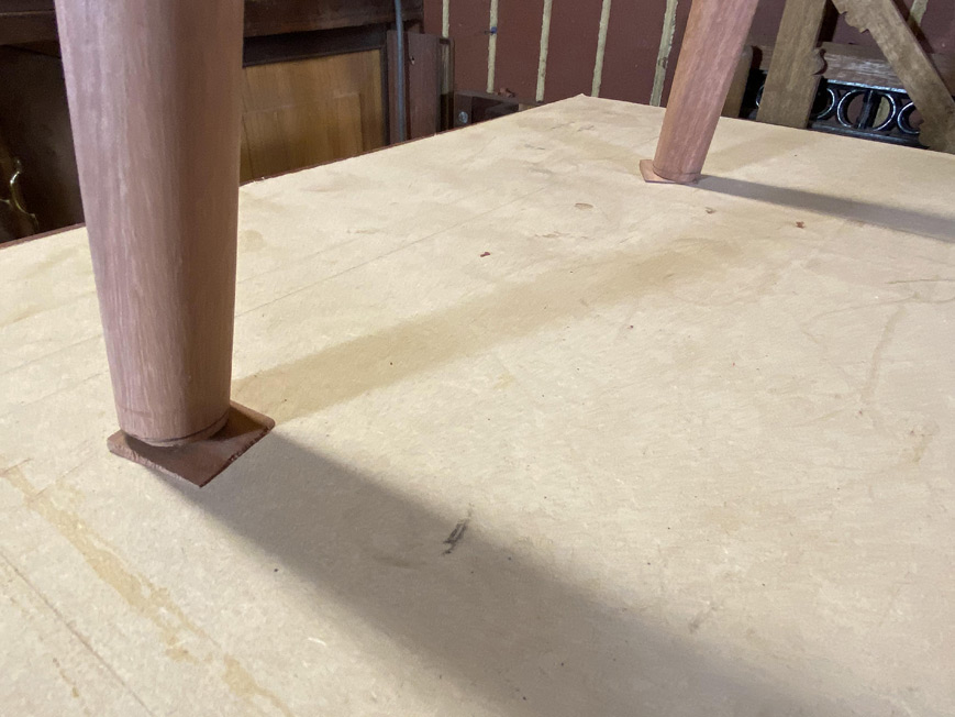
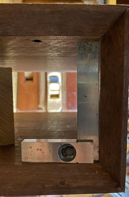
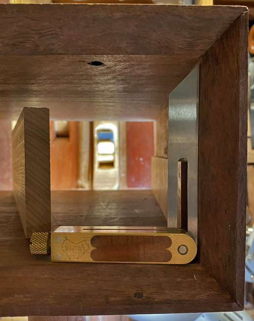
I was heartened that all the verticals were indeed vertical still ... well, except for one (if you look carefully, you will see light in the top half) ...

7a.jpg


This meant a slight adjustment of that side .. again a job for the shooting board.

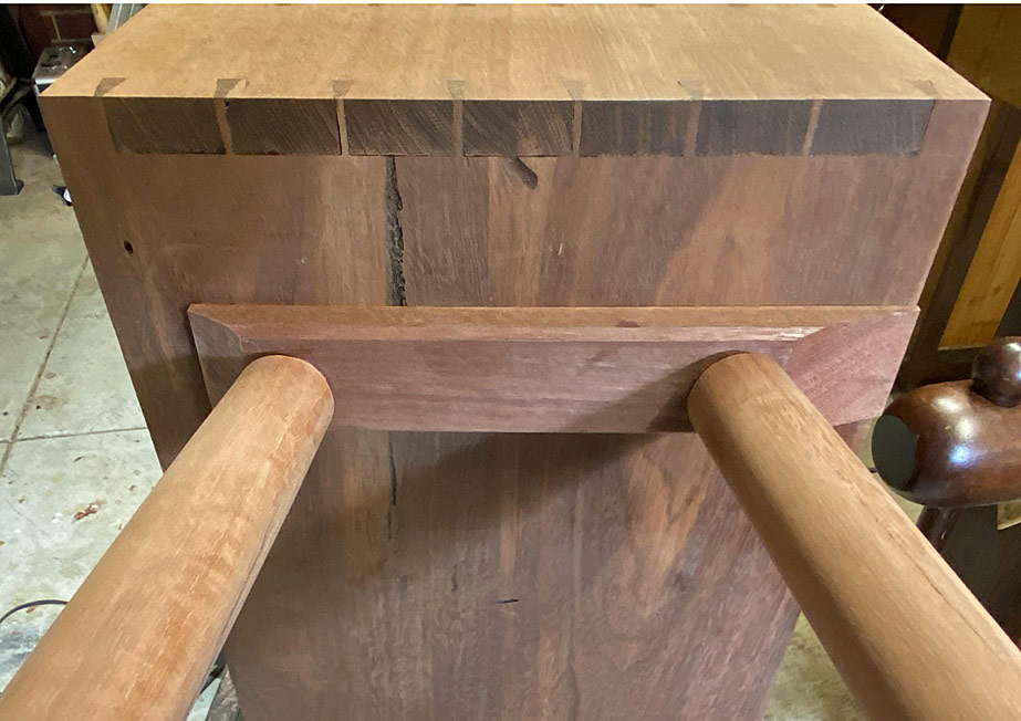
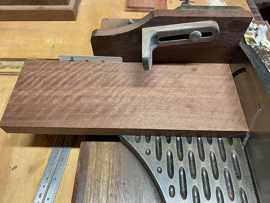
Set one, mark the angle with a small sliding bevel ...

8a.jpg


... transfer this to the side of the board, and head for the shooting board. As the side is no longer square, a shim is used to create the needed angle ...
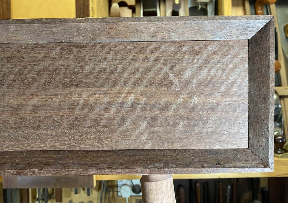
9a.jpg


A good result ...

10a.jpg


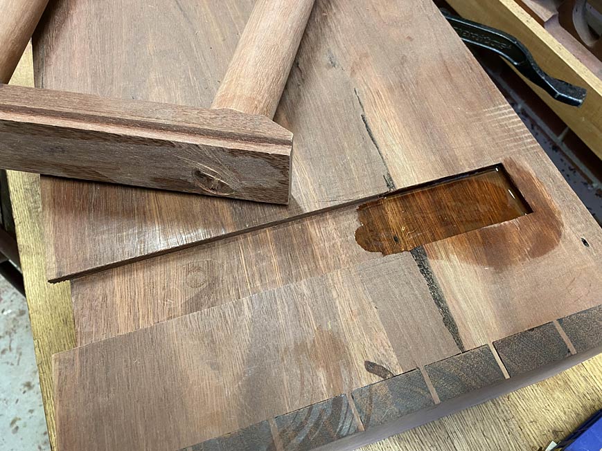
This is the join I need to manage ...

11a.jpg


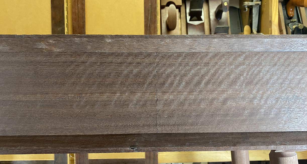
These are the fronts fitted in sequence ...

12a.jpg


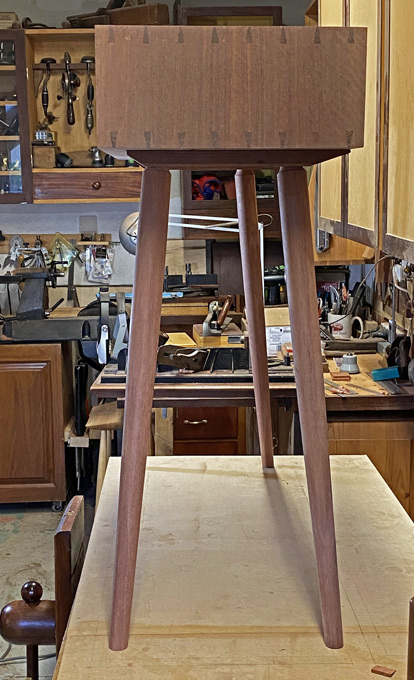
And here were are now, waiting for the next build day ...

21a.jpg


Regards from Perth

Derek
 
Beautiful.
Have you decided on the handles for these drawers? Never an easy decision.
 
The process of attaching of the legs was completed by the addition of two screws in the sliding dovetail base.

Why add screws? The screws are not to prevent the base sliding back (an elongated hole actually encourages this). It is just to prevent the base twisting in, and breaking out of, the socket since there is no glue there to prevent any lateral movement.

The force comes from the splayed and angled legs. They will want to cant outward, and this becomes more so when the three drawers are filled and a vase of flowers is placed on the top of the table.

I thought that it is worth mentioning the screws used and how they were inserted.

The screws are 1" long brass tapered wood screws. The drill bits are also tapered to match. These ones include a countersink and depth stop.

1a.jpg


The plan is to drill the hole for the screw through the base and into the case, and then widen the hole in the base. This will permit the base to move with expansion and contraction. In this case 2mm each way.

A wider drill bit (and depth stop) ..

3a.jpg


Before inserting a screw, especially brass screws, they are dipped in a little wax. This is wax for lubricating bandsaw blades ...

4a.jpg


Here is the widened hole ...

5a.jpg


The gap around the screw ...

6a.jpg


7a.jpg


The second screw is on the other side of the leg. This is positioned about half way between the end screw and the glued toe.

8a.jpg


Regards from Perth

Derek
 
I'm not sure that this arrangement will allow any movement, Derek. It's the countersink which is the issue. No matter the size of the hole, what you've effectively got is a snug fit cone-in-a-cone. In circumstances where I'm allowing for lateral movement.....yes to the oversized or slotted hole, but I use a dome-headed screw with a flat underside, and I put a washer on. If you need to bury this because it is unsightly, then you need a flat-bottomed slot. Here's how I did it with a boarded door:

PjDkvWH.jpg


FfkG6pl.jpg


I followed up with a plug (pellet).
 
Mike, I have been pondering on this. I must admit that I chose the screw first as a wood screw and that it could be recessed out of sight. My thoughts were on a wider hole for movement, and did not consider whether the conical countersink would limit movement.

To be safe, I plan to swap out the screws for round heads, and shape the countersink into a flat (using a wider forstner bit).

Regards from Perth

Derek
 
You'll need to clamp a piece of scrap over the hole because otherwise the Forstner bit will not have a centrepoint to follow and will thrash about making a mess. You know that, though........grandma/ egg sucking.........sorry!
 
Okay, so I decided that the wood screws were a mistake. They would prevent movement rather than permit it. So they had to go.

This is the exchange screw: a 12 gauge stainless steel wood/metal screw with an all-important flat/domed head.

1a.jpg


The plan was to use a 3/4" forstner bit. This would leave a wide, flat area for the screw head to move along. The range of movement would be the same as before, about 2mm each side of the screw.

A MDF template was made to guide the forstner bit, as it had no support in view of the existing hole ...

2a.jpg


Drilled to depth ...

3a.jpg


A steel washer added ...

4a.jpg


Done ...

5a.jpg


I had only 15 minutes after work today, but on the weekend, when I get back to this build, I plan to add a third screw behind the front leg.

Regards from Perth

Derek
 
I hardly like to say this and it may just be that the photos mislead. But it looks like your steel washer is a snug fit to the screw and to the recess. One or other or both needs some slack!
 
I put the last screws in after work. That will free up this weekend to concentrate on building the drawers.

There are three screws. The one at the toe is fixed and there is no play for any movement. The two at the rear can slide 2mm each way.

1a.jpg


2a.jpg


Regards from Perth

Derek
 
You know, I'm not really clear why there's a need for screws at all. This sliding tapered dovetail is held fast at one end. It can't come out of the slot. I just don't see the need for fastners at all, given that these things were originally designed to obviate the necessity for fixings.
 
Mike, the point is that this part of the build is not about drilling for screws. It is about mechanical design, that is, how to strengthen the base.

There is the leverage placed on the base by the legs, because they angle away from the base. Since the legs are very firmly attached to the base, if the legs twist (which is the threat imposed by weight on the table top) they lever the base along with them. While the base is attached with a sliding dovetail, if enough force is applied to it, it could break out sideways (laterally).

The screws are to prevent the base twisting over. The base is still free to move along the sliding dovetail (longitudinally), just not free to move laterally.

Regards from Perth

Derek
 

Latest posts

Back
Top