Where would I go to get this job done...

UKworkshop.co.uk

Help Support UKworkshop.co.uk:

This site may earn a commission from merchant affiliate links, including eBay, Amazon, and others.

NickN

Established Member
Joined
15 Aug 2016
Messages
370
Reaction score
2
Location
Stourport, Worcestershire
Rather a strange question but I'm needing a bit of advice.

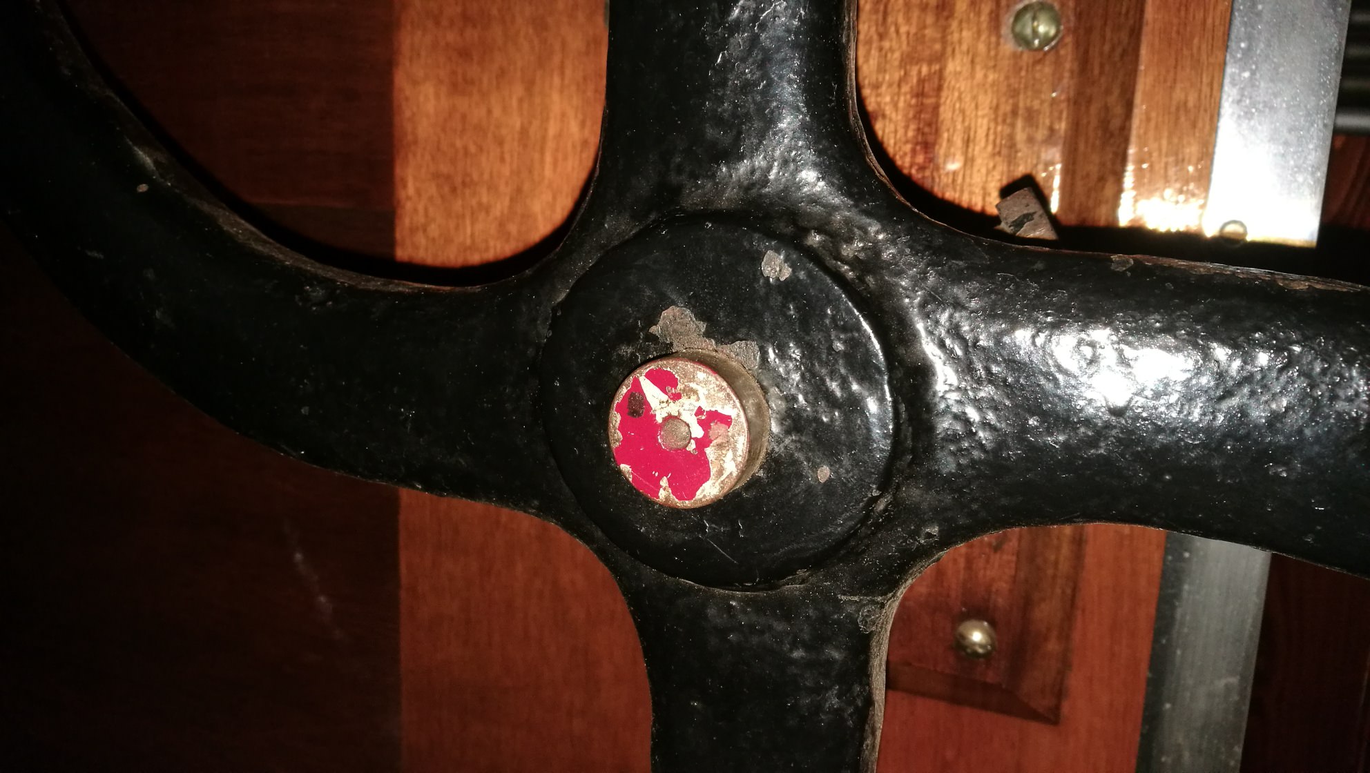
I have a large cast iron wheel of around 800mm diameter (yes, 80cm) in which I need putting a plain central hole of 23.5 or perhaps 24mm diameter for an axle (and it needs to be exactly central), plus two tapped M10 10mm holes at 12.00 and 3.00 in the collar for securing bolts, and finally another plain 10mm hole in a section of one of the spokes that is made to accommodate this. I am not entirely sure what I need to be asking for, firstly for the central hole, is it drilling or milling, and would a lathe ideally be needed to skim the rim for any discrepancy in circular shape, and finally what exactly do I need to ask for in regards to the tapped holes, is 'tapped hole' the correct terminology?

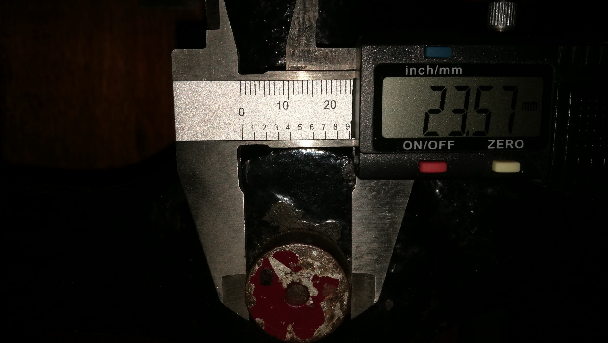
If my digital caliper shows 23.57mm on the axle, should the hole be made 23.5 or 24mm, in your opinions?

Any recommendations as to who or what type of company I might approach to do this small job in the West Midlands / Worcestershire area, too?

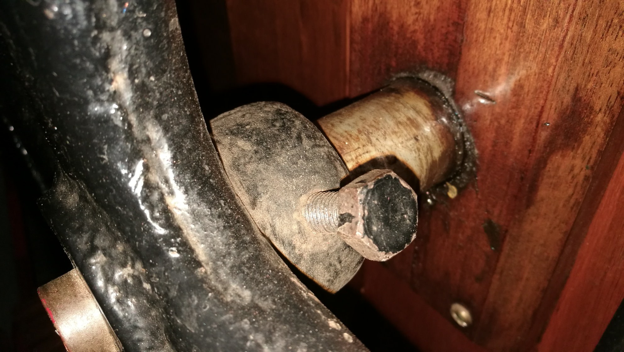
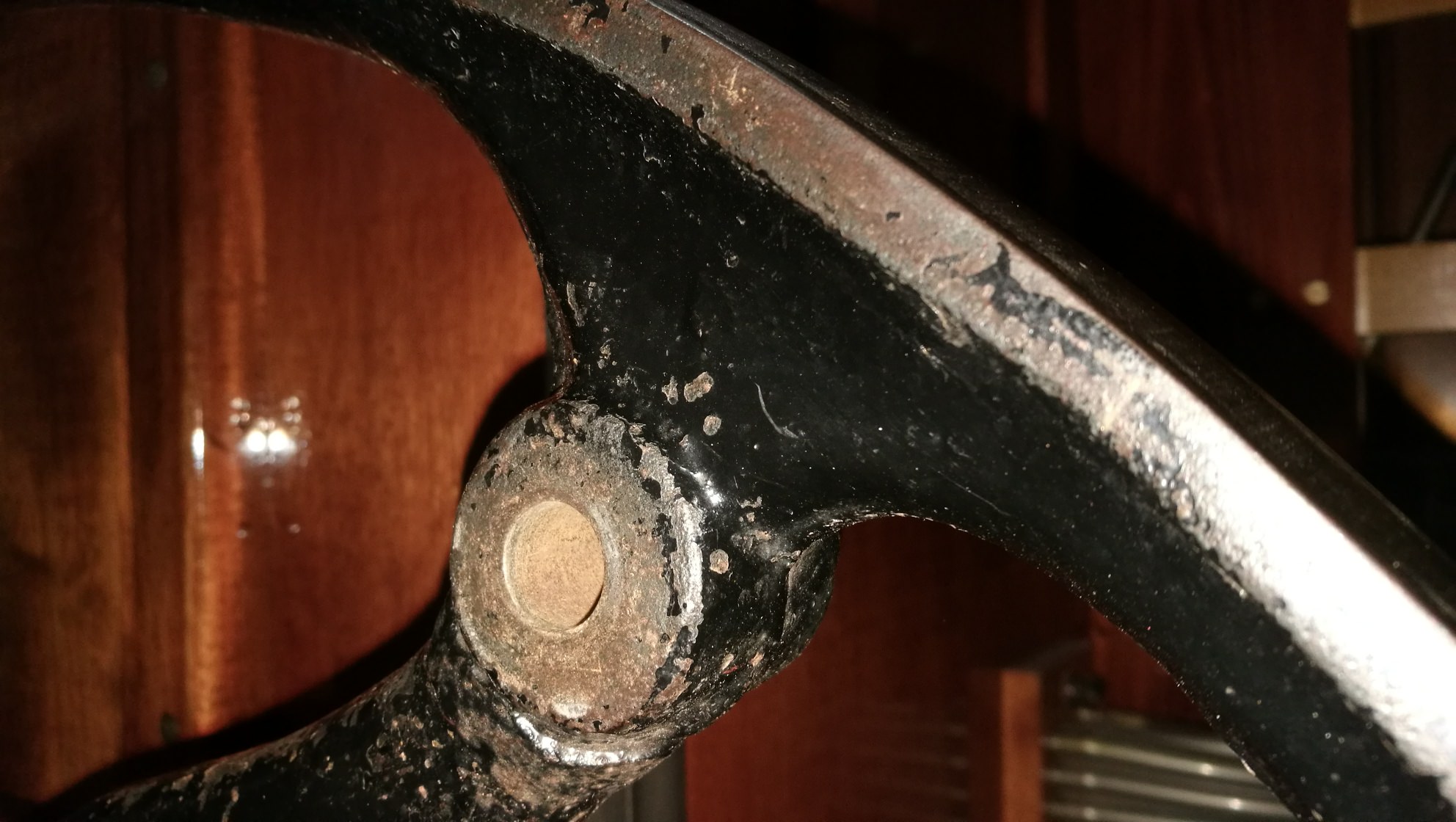
I attach photos of an existing wheel and the axle in question to give you an idea what I'm jabbering on about!

Thanks in anticipation!

1wuDUBw.jpg

GCfupNu.jpg


JFD8fwu.jpg


PUl994f.jpg
 
You don't say what the eventual application is. And we can't advise on the hole diameter since we don't know what sort of fit you want, on what diameter axle, and with what tolerance. Is it to be pressed on, or removable? If you want smooth running you should indeed skim the wheel also - if it isn't round to begin with, the centre is not defined anyway!

It's a relatively small job but needs a dirty great machine. I would recommend the following:

Jim Harris
Director

Birmingham Machine Tool Services Ltd
312-314 Bradford Street
Digbeth
Birmingham
B5 6ET

Tel: 0121 622 6339
Fax: 0121 666 6406
e-mail:[email protected]
www.birminghammachinetool.com

They reground a lathe for me last year, did a fine job and were very helpful. They will also be able to advise you in the light of your project. And they have some massive machines, and will know which is best for you.

Good luck!

Keith
 
MusicMan":kodya87r said:
You don't say what the eventual application is. And we can't advise on the hole diameter since we don't know what sort of fit you want, on what diameter axle, and with what tolerance. Is it to be pressed on, or removable? If you want smooth running you should indeed skim the wheel also - if it isn't round to begin with, the centre is not defined anyway!

The wheel will be flat belt driven from a small motor, so absolutely perfect round is not strictly necessary, just 'as close as possible'.

The axle measures 23.57 - 23.60 mm on a digital caliper and the wheel would need to be removable, so I'm guessing that 24mm would be a decent fit.

I shall contact the firm you mentioned next week, thanks very much for the recommendation!
 
This job is quite well suited to a vertical lathe. Chuck axis is vertical, gravity is helping to keep the workpiece sat on the chuck. The weight of this is trivial for that type of machine, 800mm dia is not so bad. A "VTL" would be able to bore the centre hole accurately and skim the outer edge if required.
For the hole in the spoke, a drill or a mill could do the job as the hole is near the edge and this doesn't need a tool with a big throat. A larger ("radial") drill or a mill could probably do the axle hole too.
Lastly, putting your holes at 12 and 3 o'clock looks like a tricky task as these are quite close to the corresponding spokes. It would help to be open to other options from your machine shop. Moving the holes 45 degrees (midway between two spokes) would make more room to get a hand power drill in.
Exactly as musicman says, you have a small job but the diameter of the wheel means you need a physically big machine. Be aware that the people who own those need to make them earn their keep.
 
Is that bolt head(best seen in pic 3) the way the wheel is retained on the shaft? Does the shaft have a mating flat on it where the bottom of the bolt comes through the hub and "lands on" the shaft? If the answer to both those is YES, then a hole diameter of 23.60 mm should be fine.

What is the purpose of the 2 x 10mm holes at 10 and 3 o'clock?

As the other posters have already said, the job is not difficult really, but the work piece dimensions dictate a pretty BIG machine! BTW, a lathe isn't the only machine that will do, a jig borer or milling machine would do it as well.

As to firms who can do that in your area, I have no idea, sorry. Sounds like MusicMan's suggestion is based on his own experience, and that's always a good starting point.

AES

P.S. Just for my own "nosiness", what on earth are you doing please?
 
It looks like it could be for a treadle powered machine. A lathe perhaps. I would make the bore 0.1mm over the shaft diameter. When you take the wheel to the machine shop you should also take the shaft. The machinist doing the work can then measure it with tools that are calibrated or ones that they are familiar with. Even though callipers can display two decimal or more places they rely too much on operator feel and no two of us have the same feel. Micrometers are better suited.

If the shop is well equipped it could all be done on a 5 axis CNC mill in a single setup once clamped with the clocked holes side up. Once the centre is established it could be drilled and bored or a milling bit used to interpolate the hole to size and then the same bit can true the outer rim by interpolation. Spoke hole made and if there is room in between the spokes for the head it it could do the clocked holes in the hub. If the milling machines head is too big to fit between a 90 degree boring head put in the machine to do the holes.

While it looks straight forward and can be done in a number of ways, it will be costly. The Aerospace machining factory I worked in would bill work of that size for at least hundred and fifty bucks an hour plus the programming. I don't see a shop with older manual equipment being much cheaper unless they are intrigued with it and fit it in between jobs.

Pete
 
+1 for Inspector's points about using a micrometer rather than a vernier (even if digital). There's feel involved in using a mic correctly & repeatably, but more so with a vernier. +1 also for taking both the shaft and the wheel with you.

And another +1 for "likely to be expensive", but I GUESS your best hope will be to find a small old-fashioned shop that's not rushed off their feet and where an experienced machinist might be induced to doing some Saturday morning overtime more or less "just for the fun of it".

How you find such a place though I don't know. To me it sounds like a mates network type of thing, so good luck with that.

AES
 
Thanks for the helpful information - I took the existing wheel off today and checked the retaining bolt - it's a simple cone tipped bolt into a shallow depression in the shaft, so no friction is required for the fit as such.

The current wheel would be the template in all respects, the reason it's being replaced is that at some point in its past, it got broken and badly re-welded / brazed back together, so that it doesn't run anywhere near true in any plane, whereas my new replacement wheel is a copy of a known good one.

And to satisfy the curiosity, it is a wheel off a mechanical organ - so the shaft is actually a crank shaft driving bellows - hence I won't be able to take the shaft to a machine shop, but I can take the old wheel which should be good enough hopefully.
 
metal table, a couple of wedge clamps and a mag drill. :)
it won't be quick, it won't be easy and it wont be perfect, but it'll be damn close, cheap and done by your own fair hand. :) it's for a flat belt, it doesn't need to be perfect.
you could also do it on a pillar drill, if you take the top off and put the wheel over the pillar.

also, you could easily reduce the pulley to half that size if it's driven by a motor, you can get the torque from the motor instead of from the hand now. just saying. :)
 
Ahhhh, a mechanical organ. Now it's a bit clearer.

Yup, I understand now why you "won't" take the shaft with you! :oops:

Not sure if novocaine is right or not (I know nothing about organs) but IF you can satisfactorily reduce the diameter, the job becomes easier - much easier the smaller it becomes. It was only the big diameter that got several of us worried, purely on account of machine capacity. IF you can get it small enough then I think novocaine's dead right, you ought to be able to do it yourself on a pillar drill. BTW (don't want to teach grannie to suck eggs) but a lot of people think cast iron's a pig to work. Actually it isn't, normally it machines very nicely, it's quite soft and about the only thing you MAY have to worry about is any sand inclusions stuck in the casting, and/or air bubbles. Neither of which should apply if the foundry did a decent job originally.

HTH, and let us know how you get on, it sounds interesting. Do you play the organ yourself?

AES
 
Back
Top