


katellwood
Established Member
I’ve just completed a pair of driveway gates. These are for myself and are part of a long ongoing project whereby I have created a new driveway. This has included digging out a few tons of earth, laying brick retaining walls which included elements of curved brickwork, laying approx 15m2 of granite setts and setting green oak posts to carry the gates.
For those interested I’m going to go through the procedures I carried out in making them and identify the problem solving techniques I utilised when using large and heavy materials without assistance.
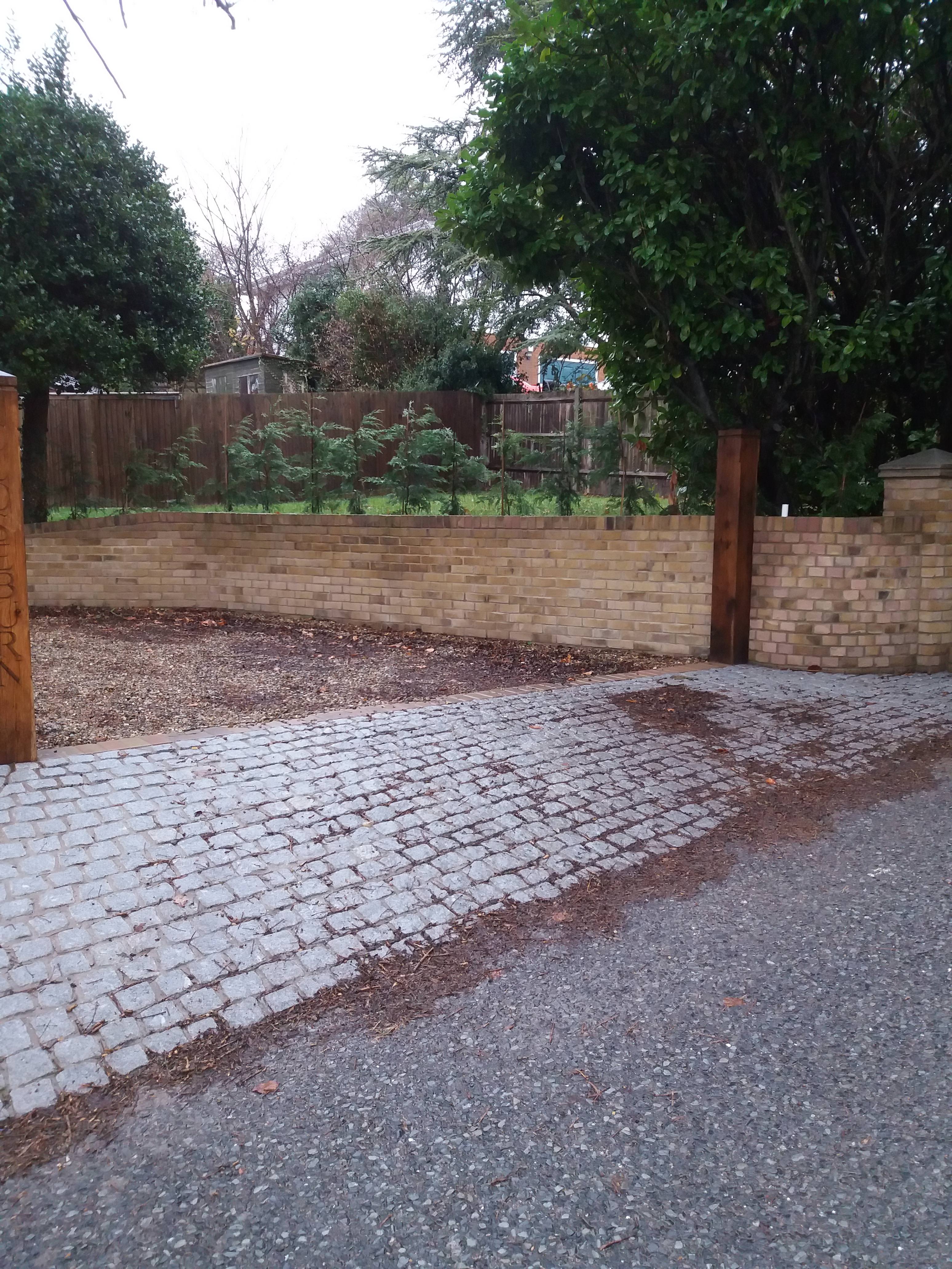
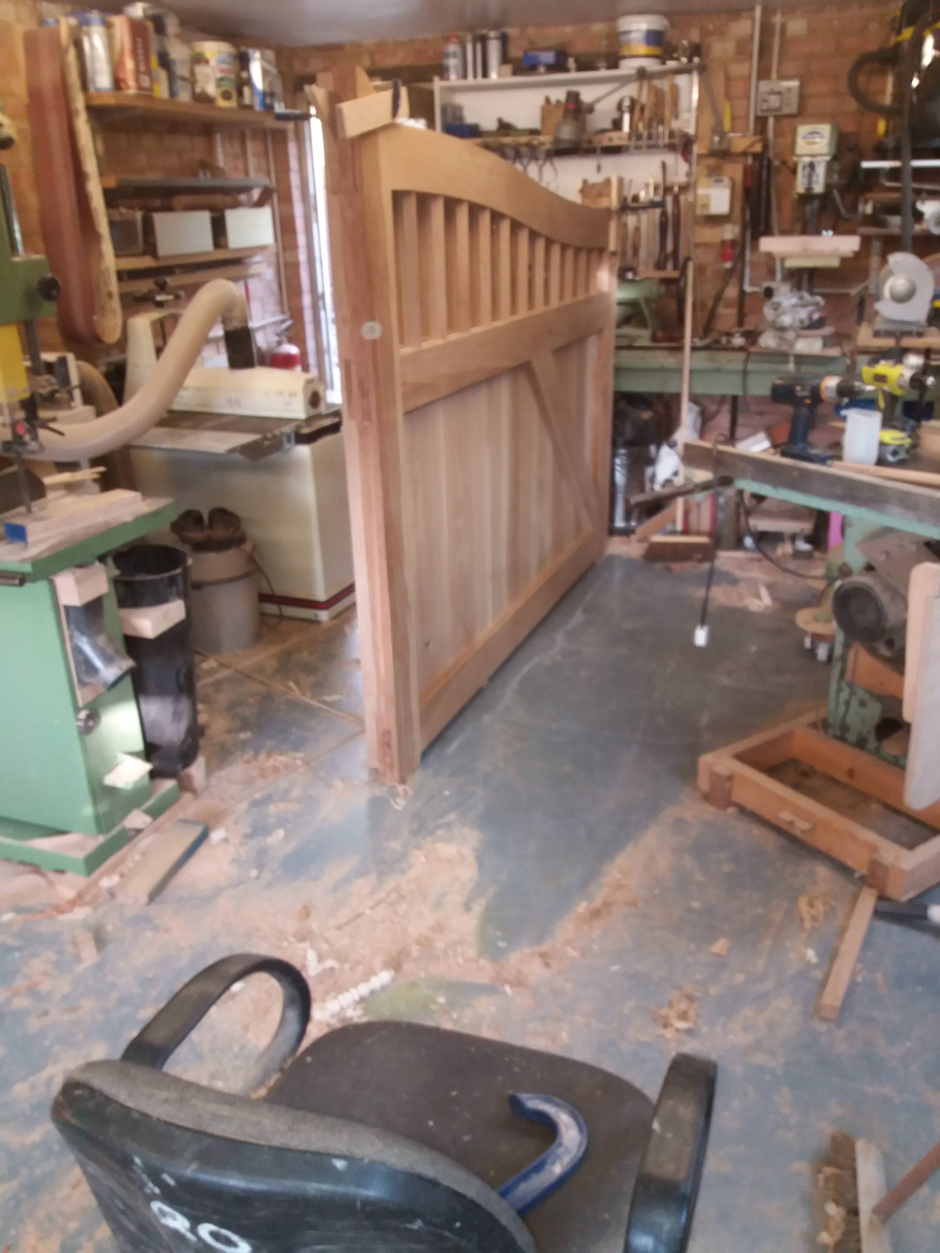
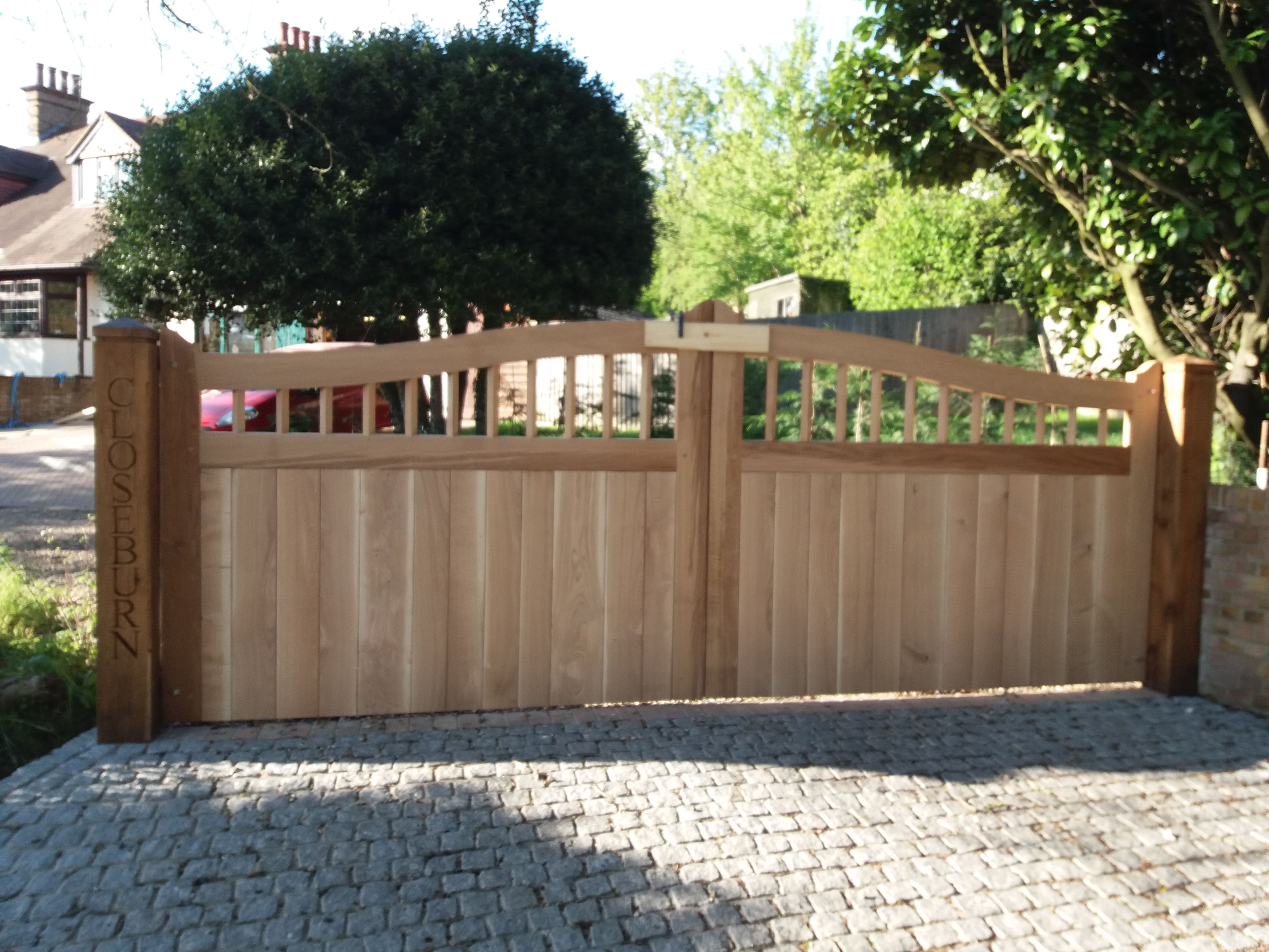
This is the opening where the gates are destined to go:-
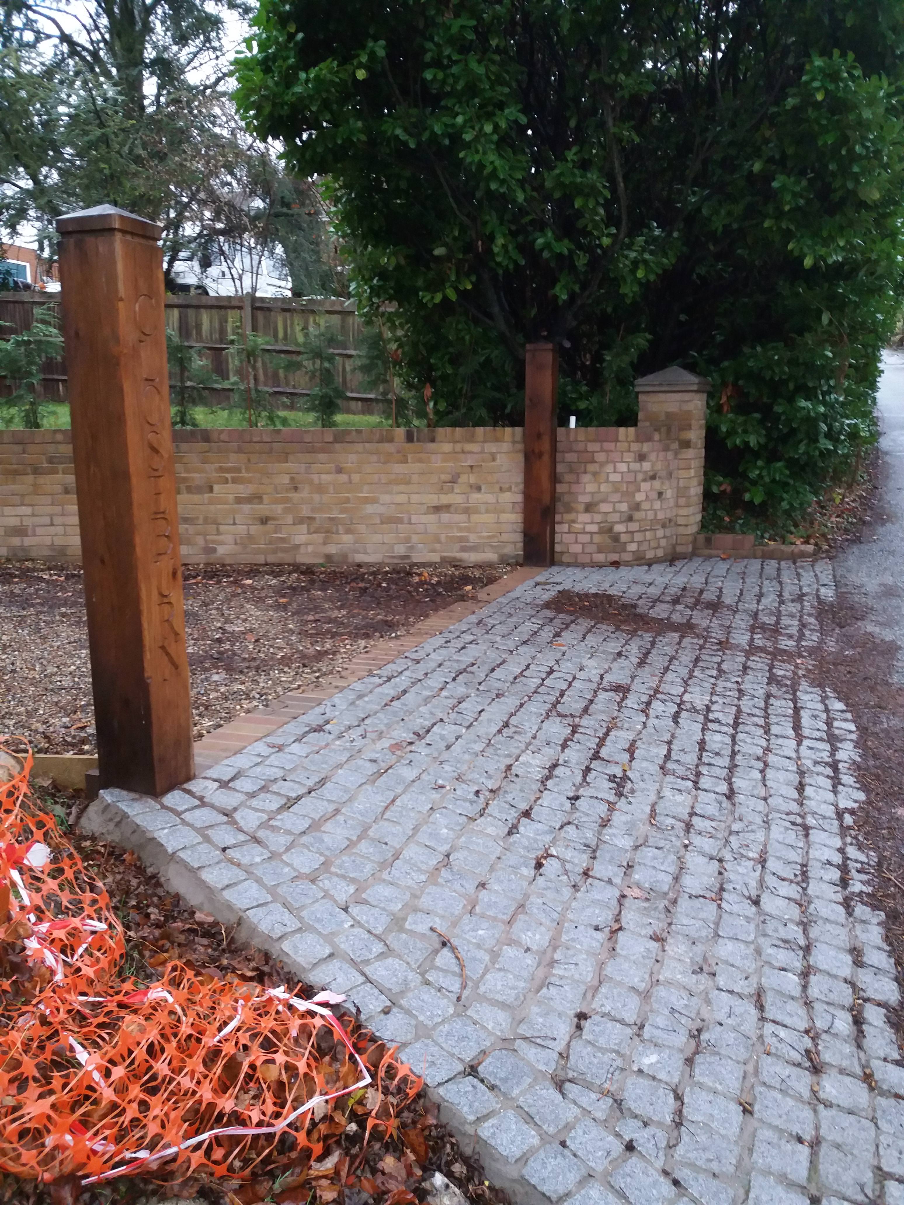
The width of the opening is 4630mm (needed to be this wide so as to facilitate access for my Landrover with the angle of the driveway to the road and the awful steering lock my landrover has).
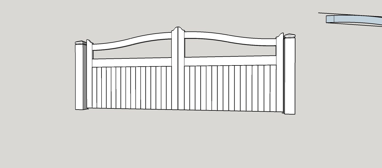
A sketchup of the intended design is shown here.
Sourcing appropriate material out of air dried oak for this project was proving difficult, eventually I decided on kiln dried French oak and purchased a pack of 80mm (they did 55mm and 80mm, I considered 55mm to be slightly too thin).
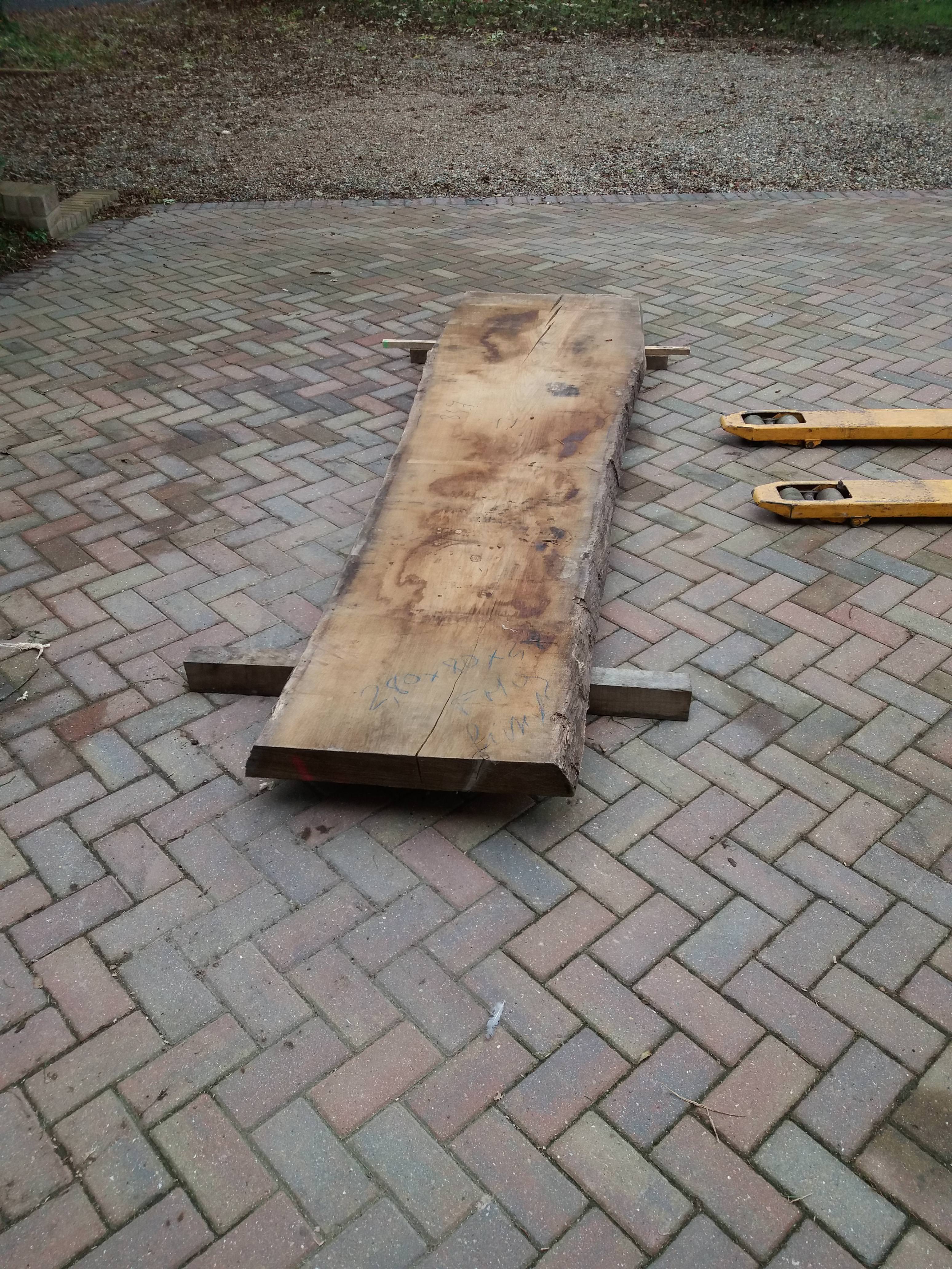
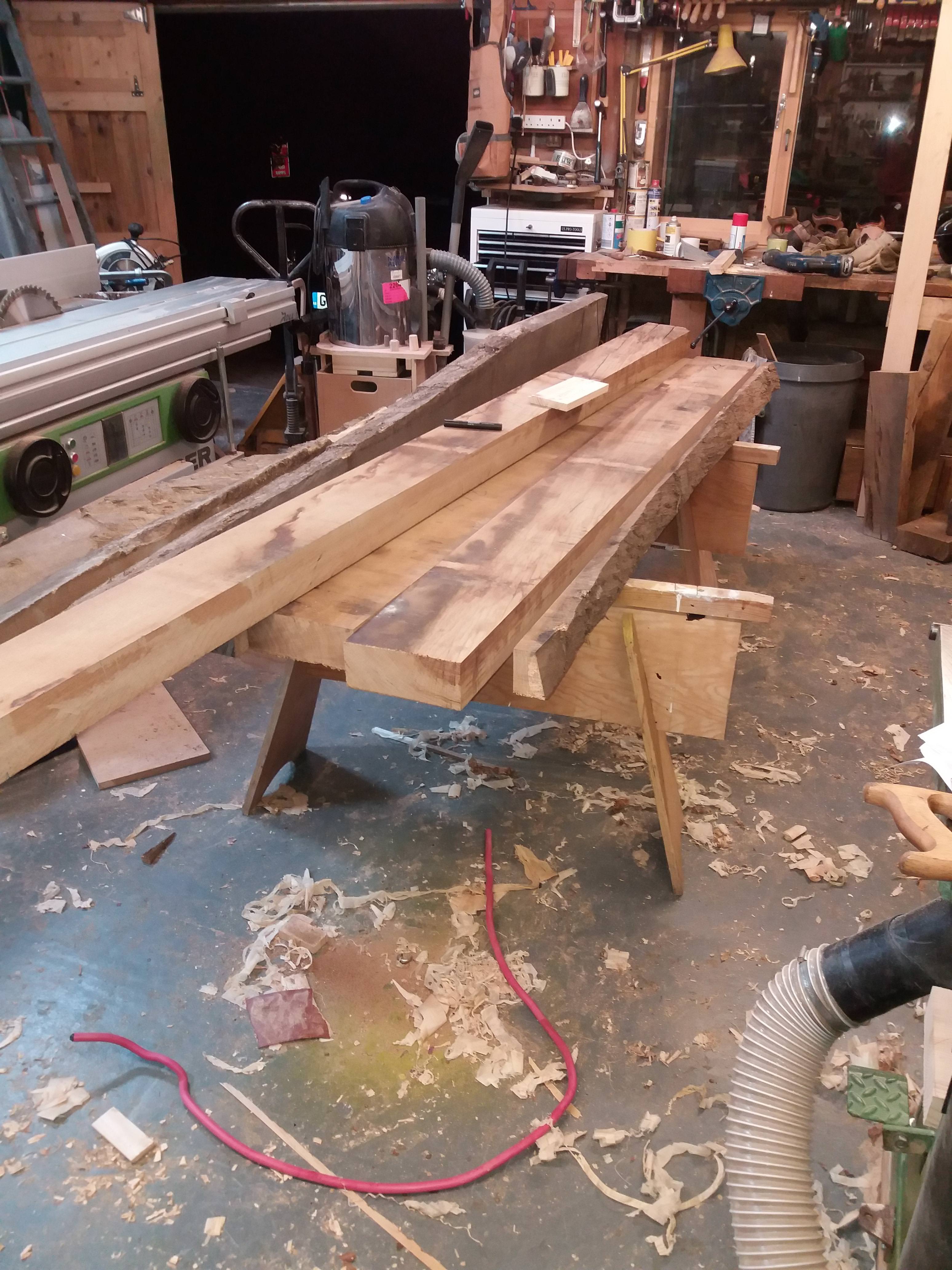
The timber as collected:-
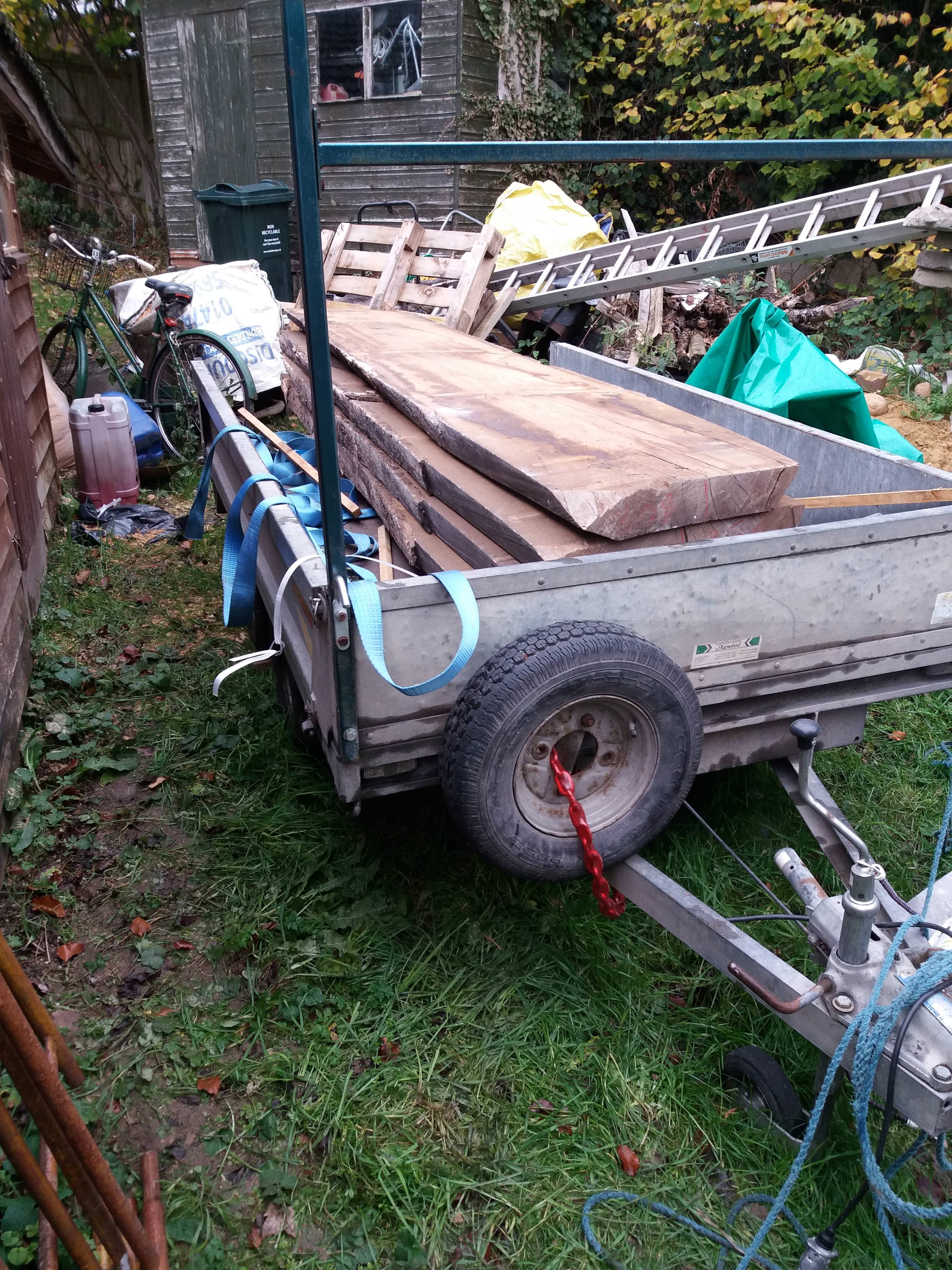
It took some effort to get it off the trailer on my own but I eventually managed it
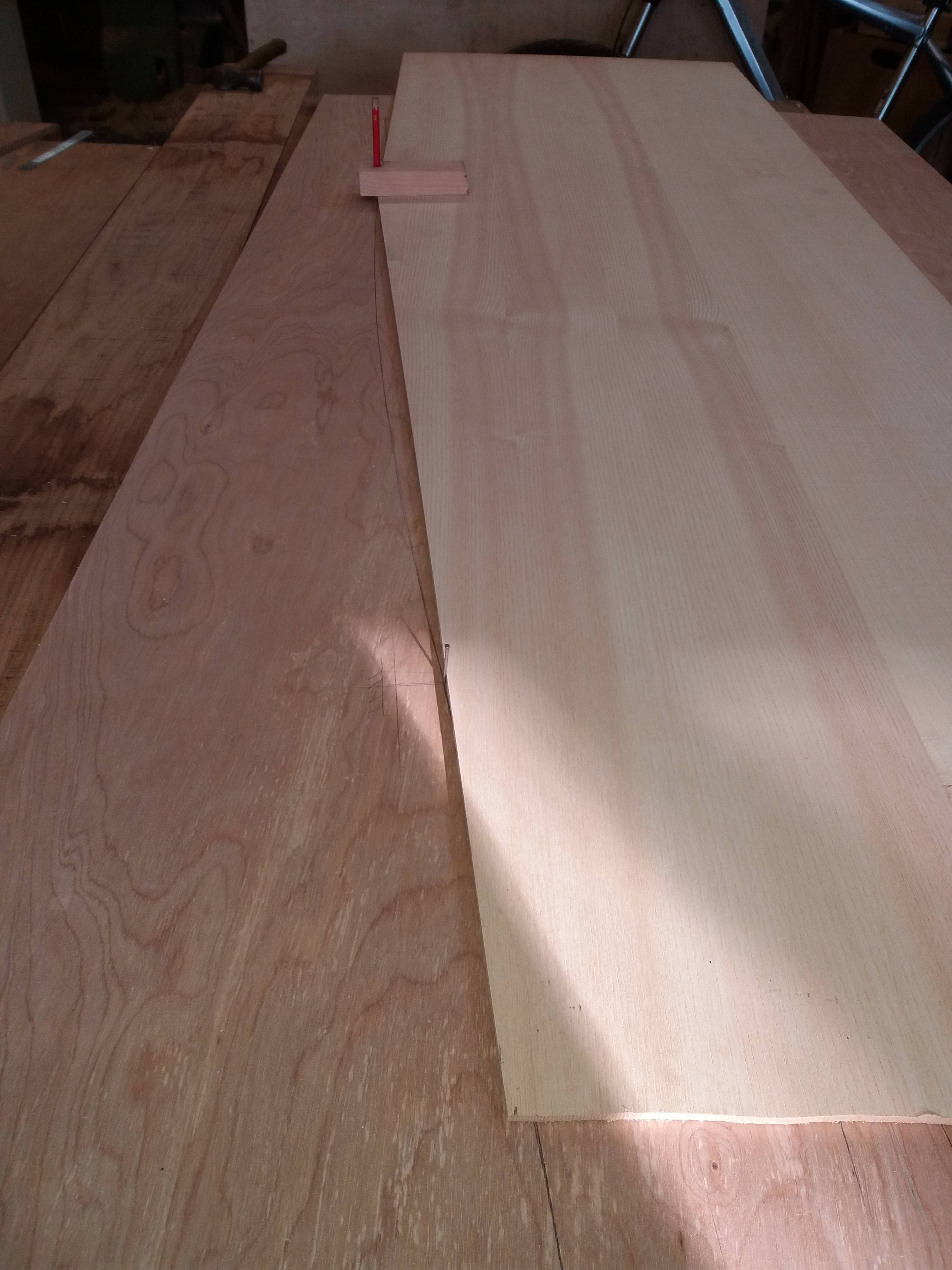
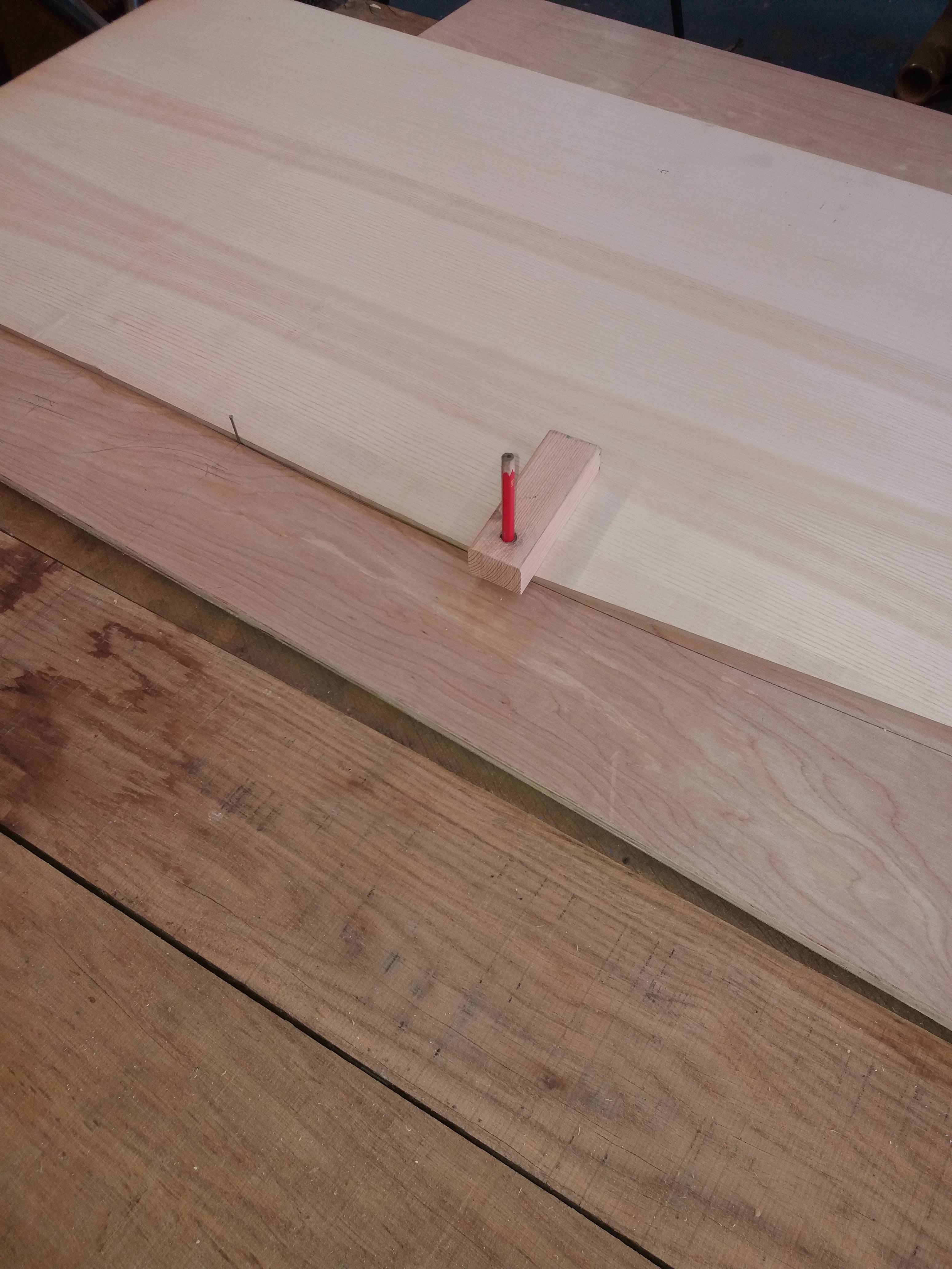
But getting it on machinery alone would prove beyond my reach, therefore with the aid of a chalk line, a straight edge and a 75mm circular saw I managed to get it down to manageable pieces.
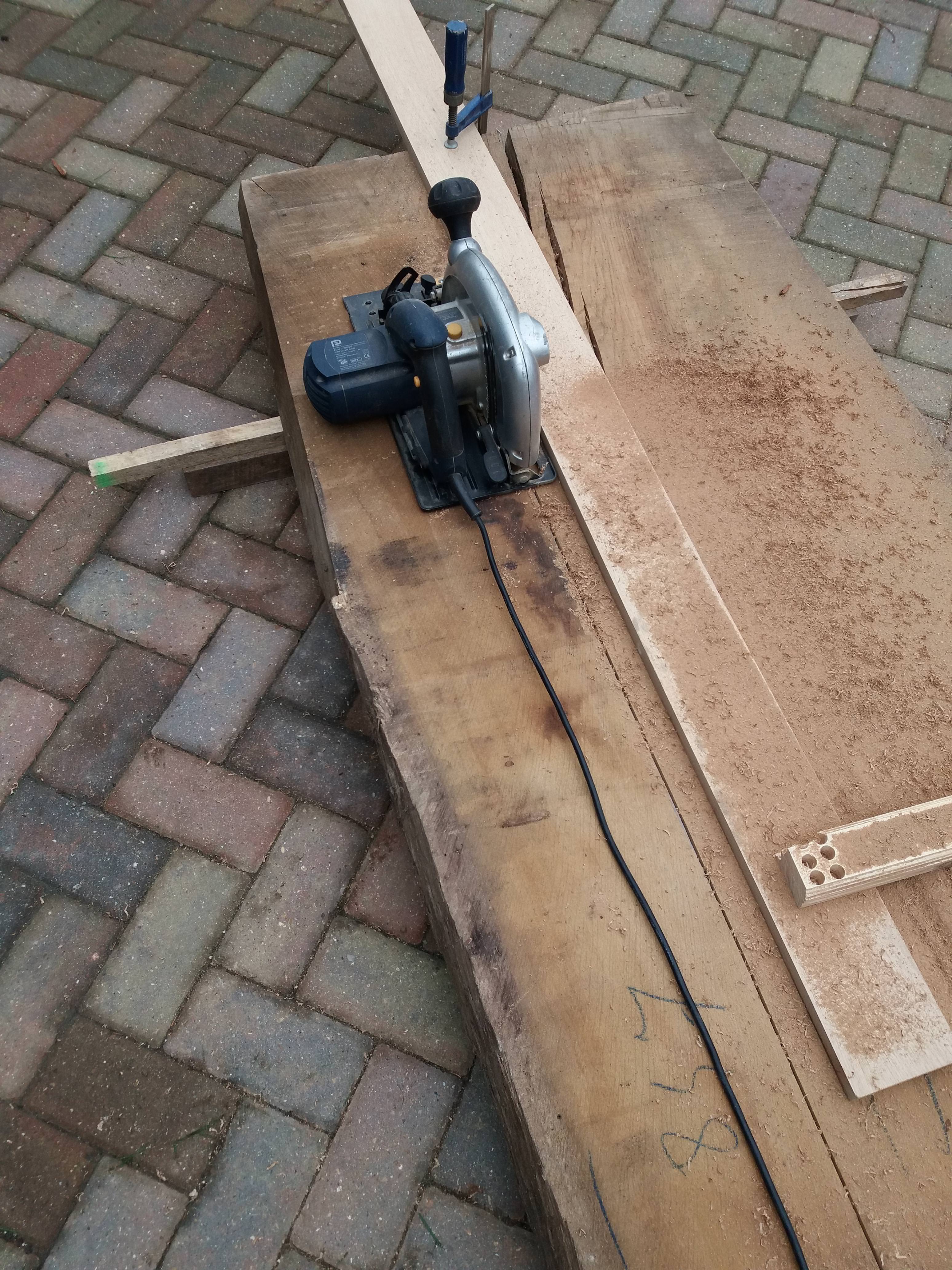
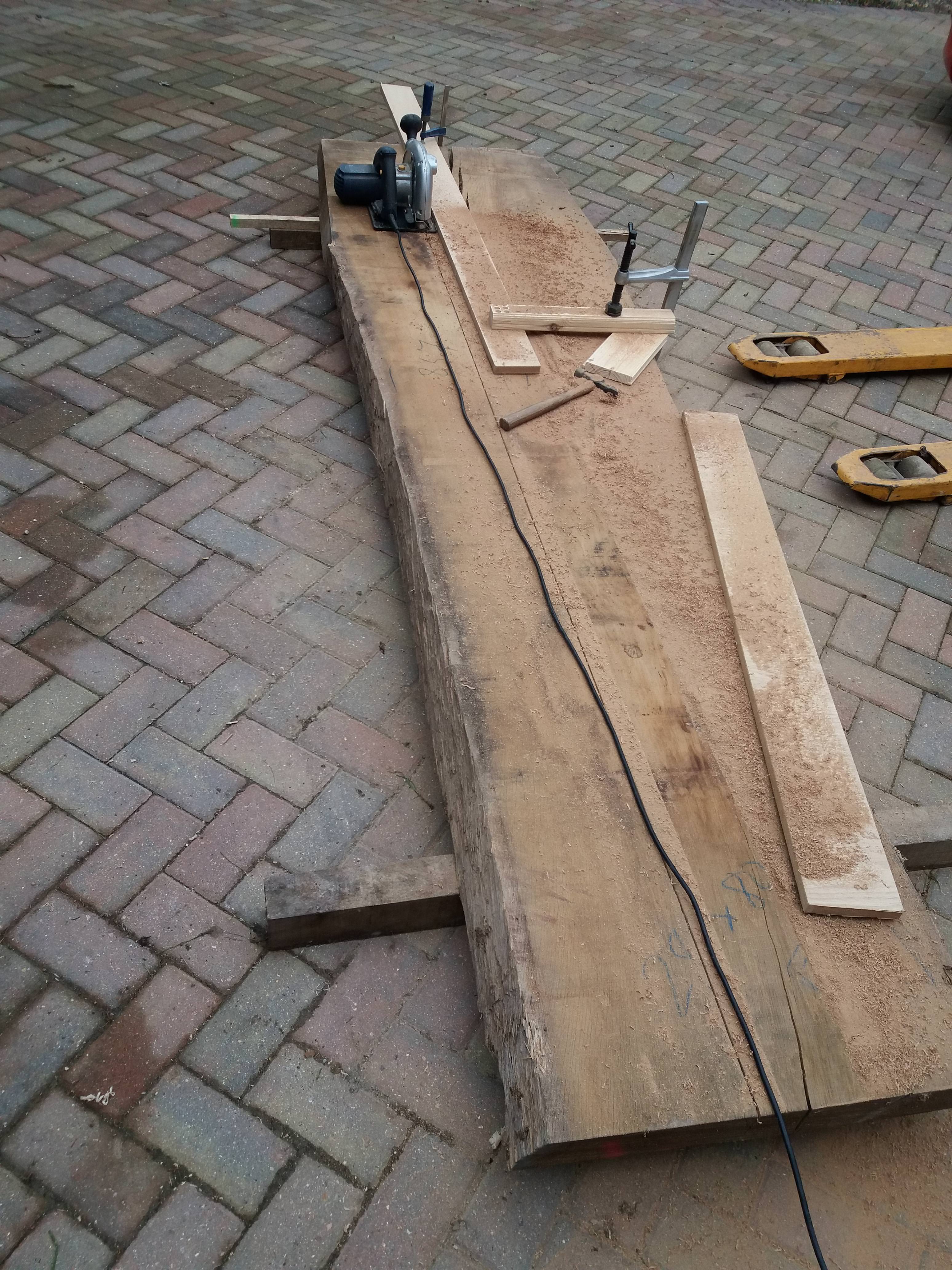
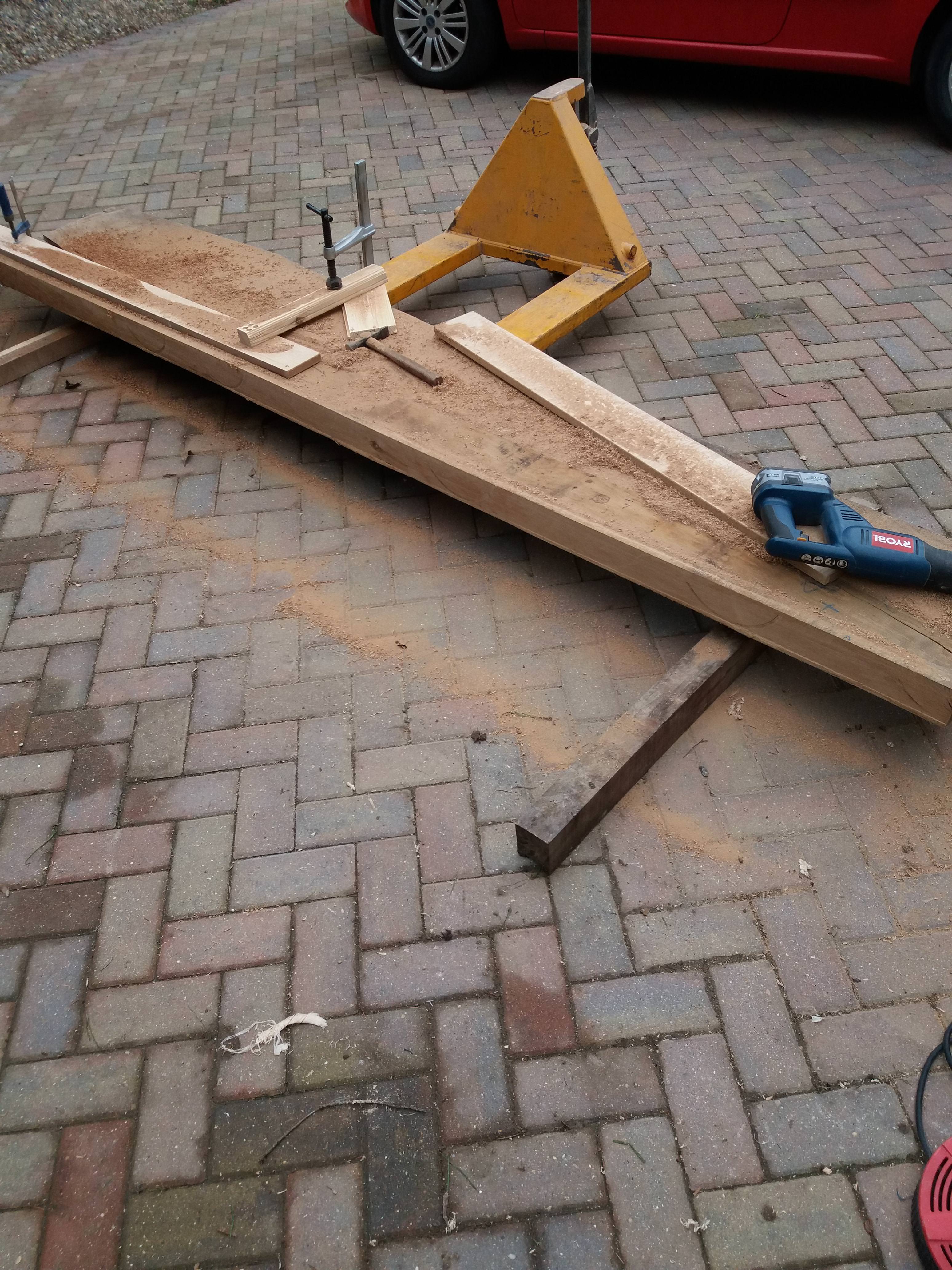
The saw wasn’t quite deep enough to cut right through so a recip saw was used for the last 5-10mm
Once down to manageable pieces I was able to cut off the wane on the table saw and get it ready for preparing. The widths of the stiles, middle and bottom rail being 150mm finish and the top curved rail approx 200mm
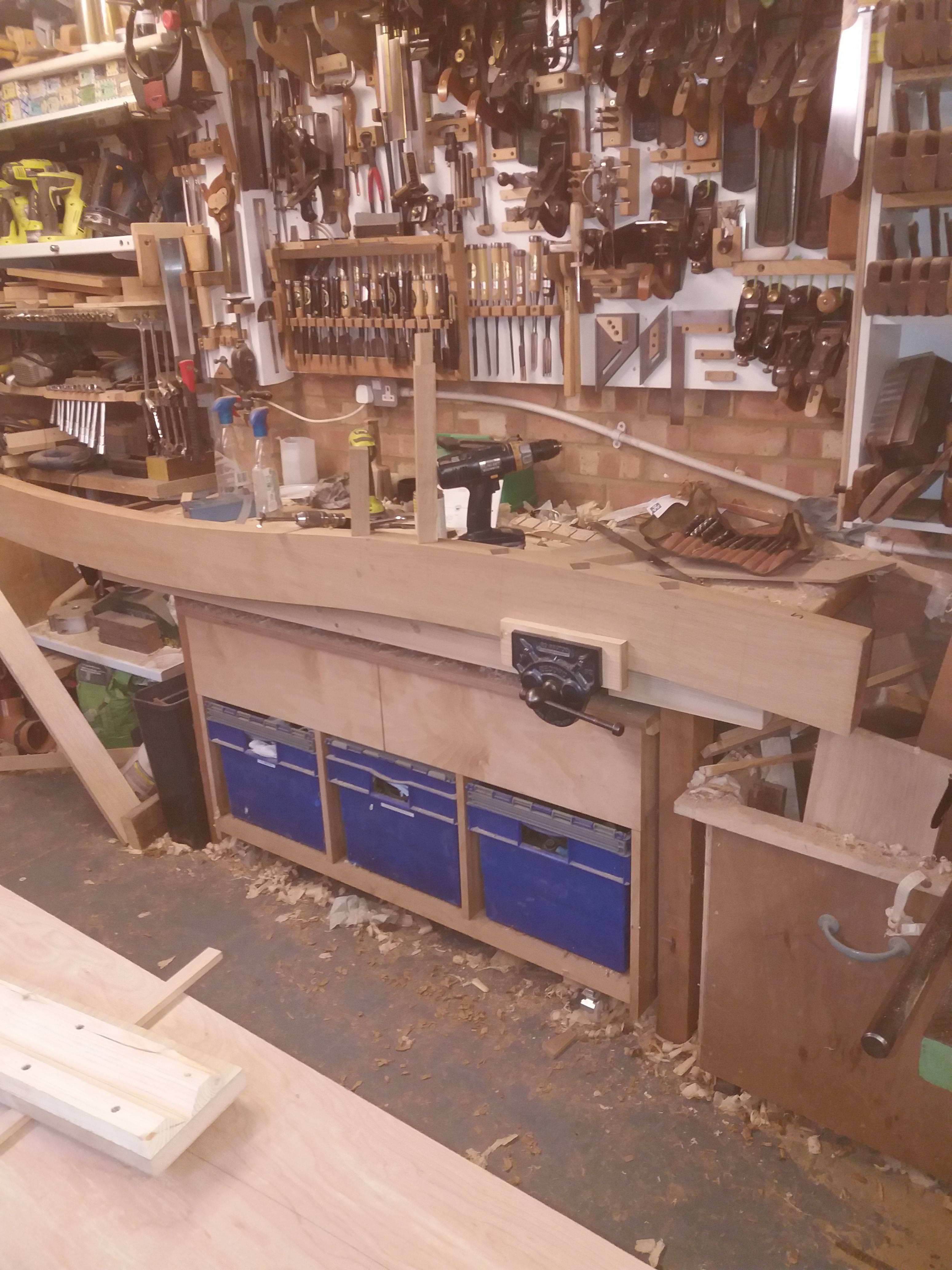
Each gate was going to be approx 2300mm wide and 1850mm at its highest point plus being 80mm+ thick I wasn’t going to be able to surface them flat on my own, so I made this
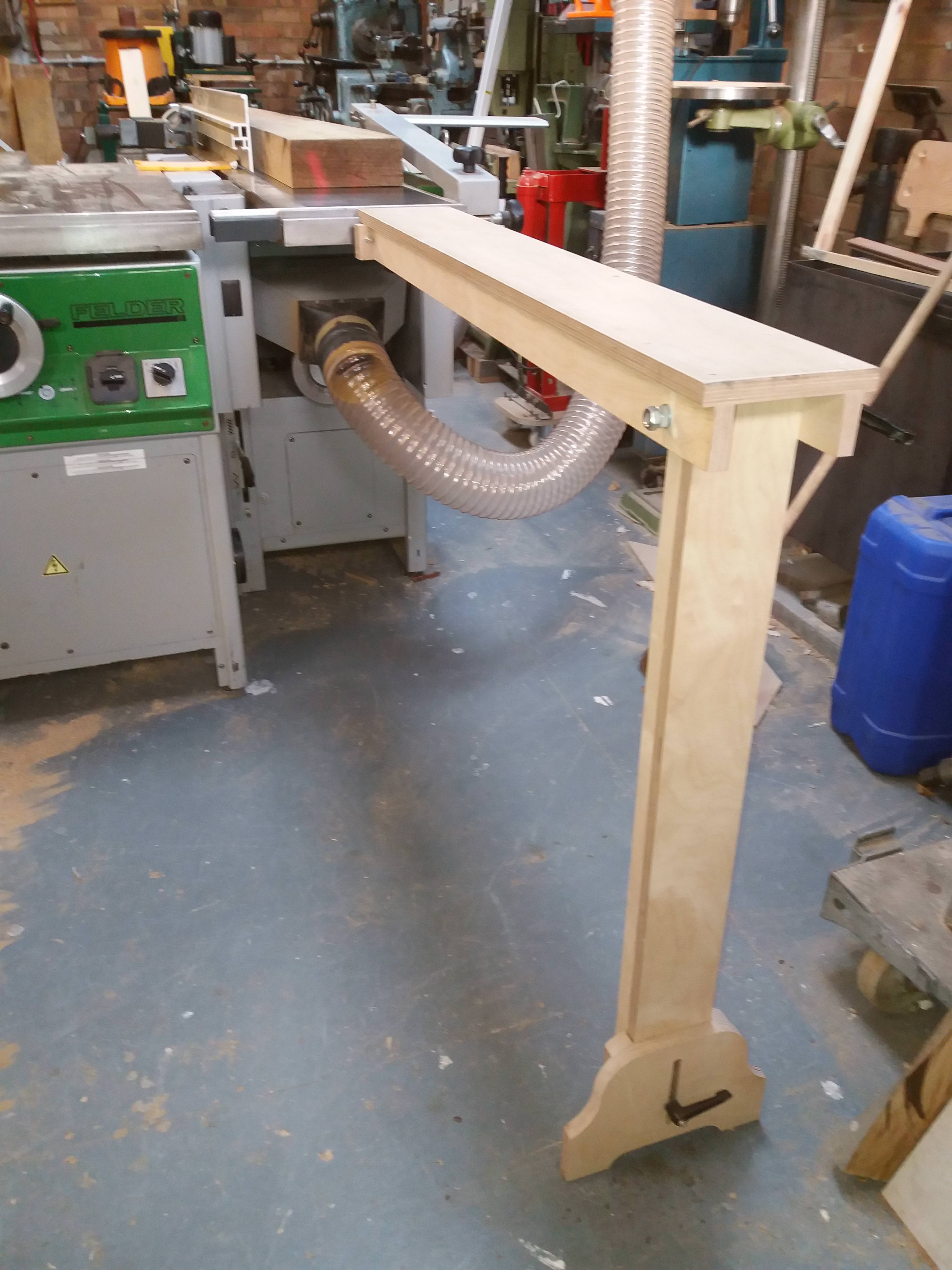
This has the facility to make it coplanar to the exit table and folds away for storage.
In use
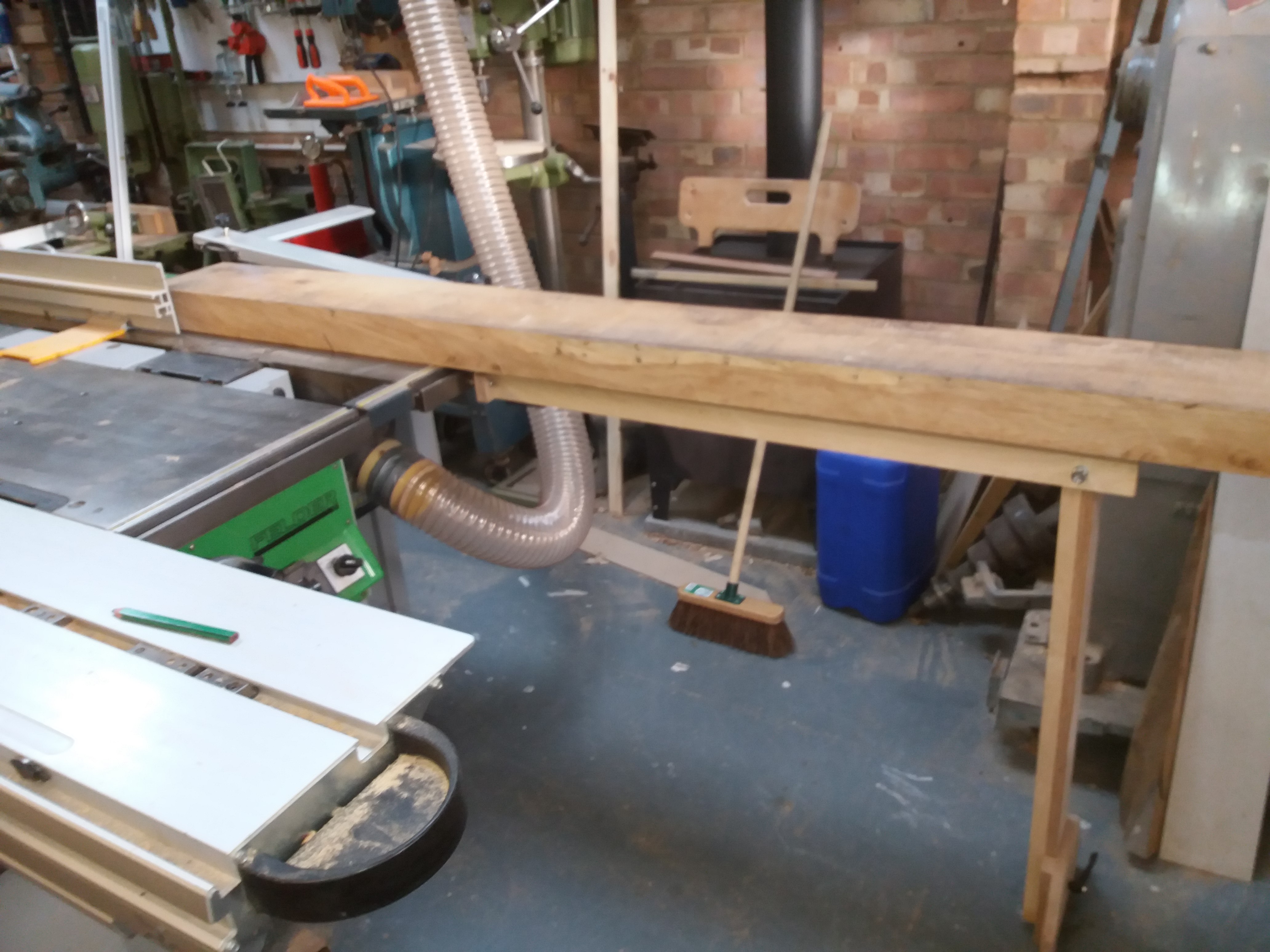
It supported the weight excellently producing a perfectly flat face side.
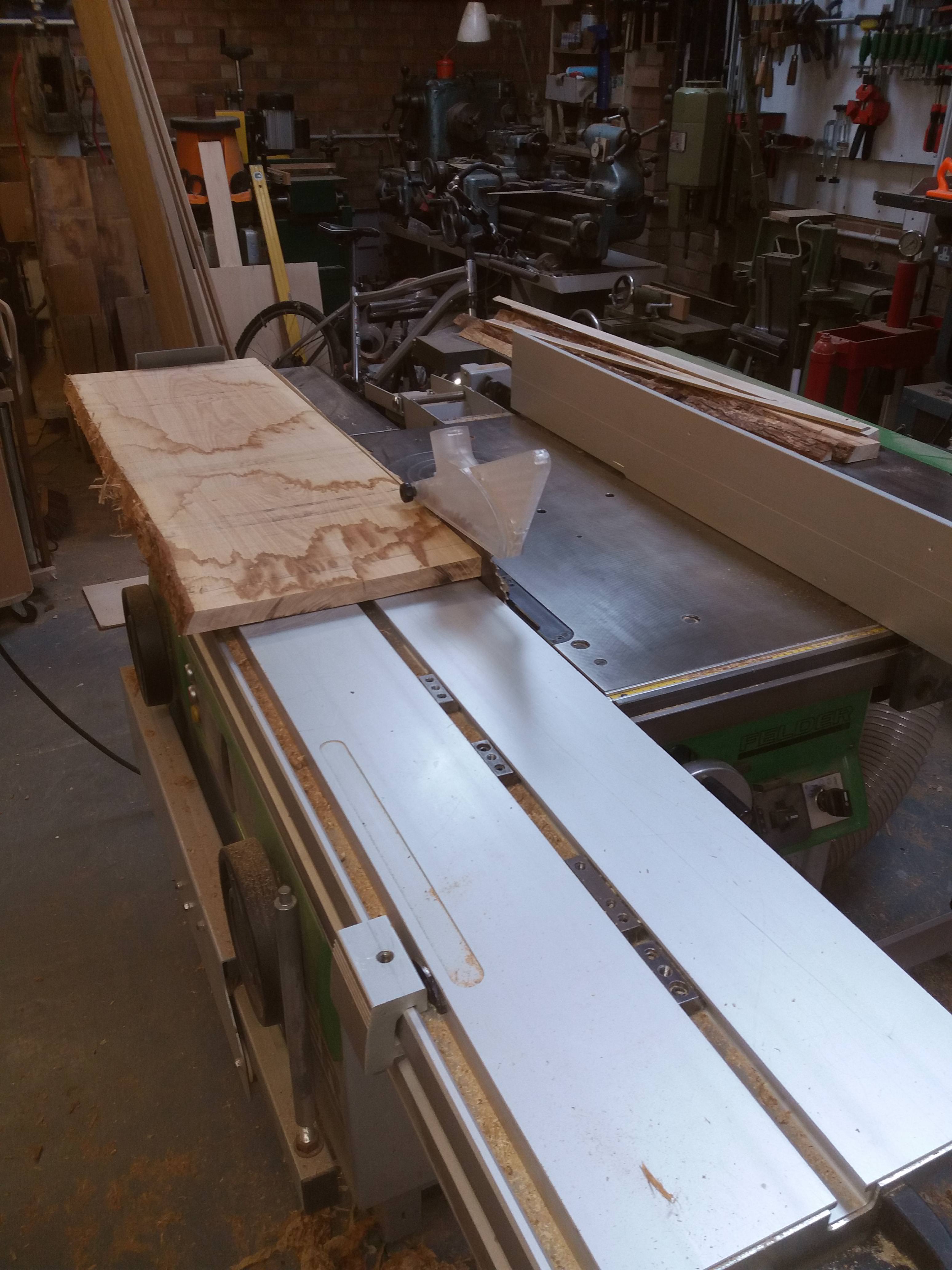
Now the face edge, using the surface planer this would have required me to not only support the timber over the cutter but to also keep it tight up against the fence and with it initially being somewhat out of square I took a different approach. I used the spindle and the sliding table as shown
The timber being clamped down and fed through the cutter. This not only ensured a perfectly square face edge but also a straight one as well.
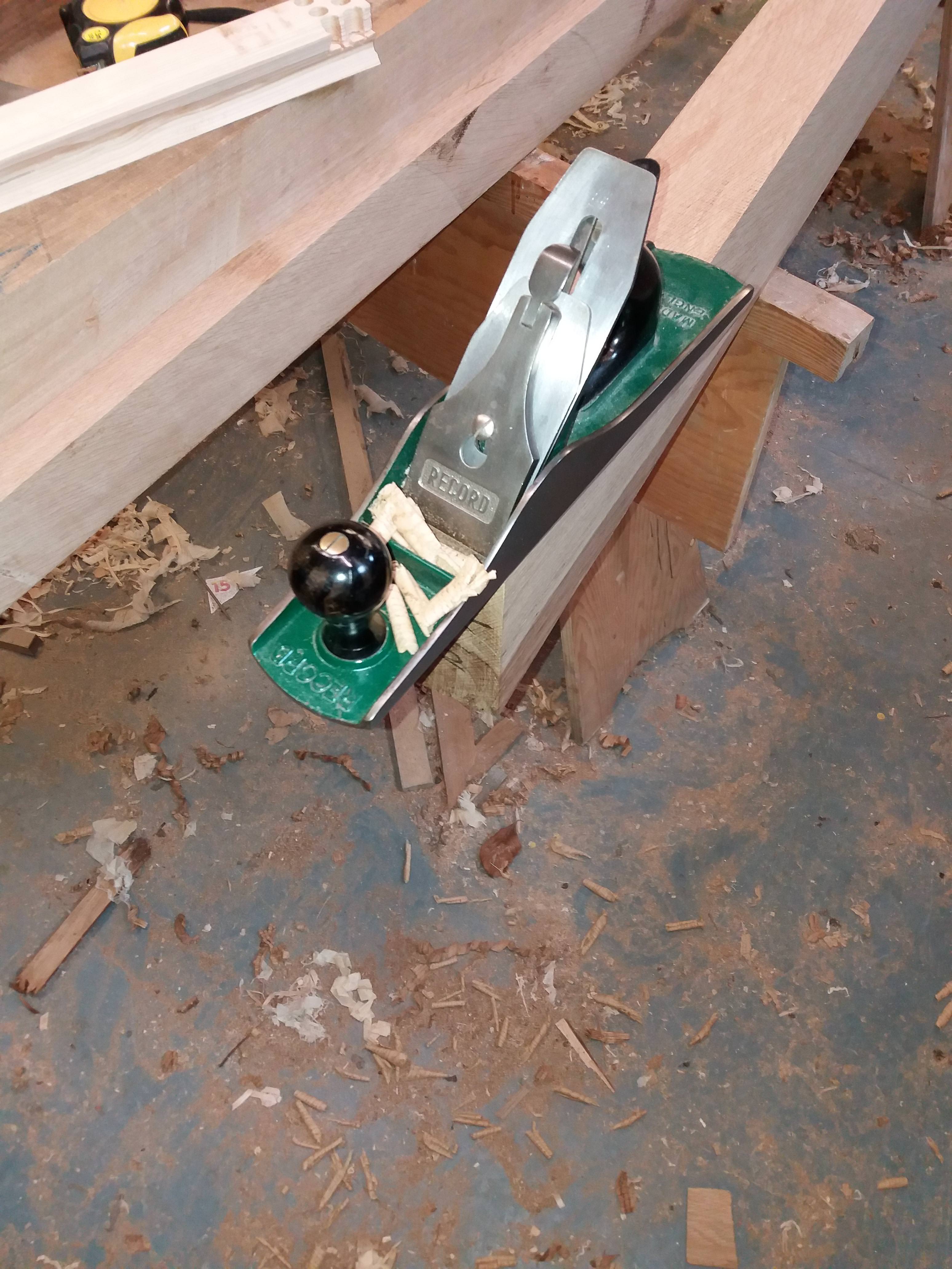
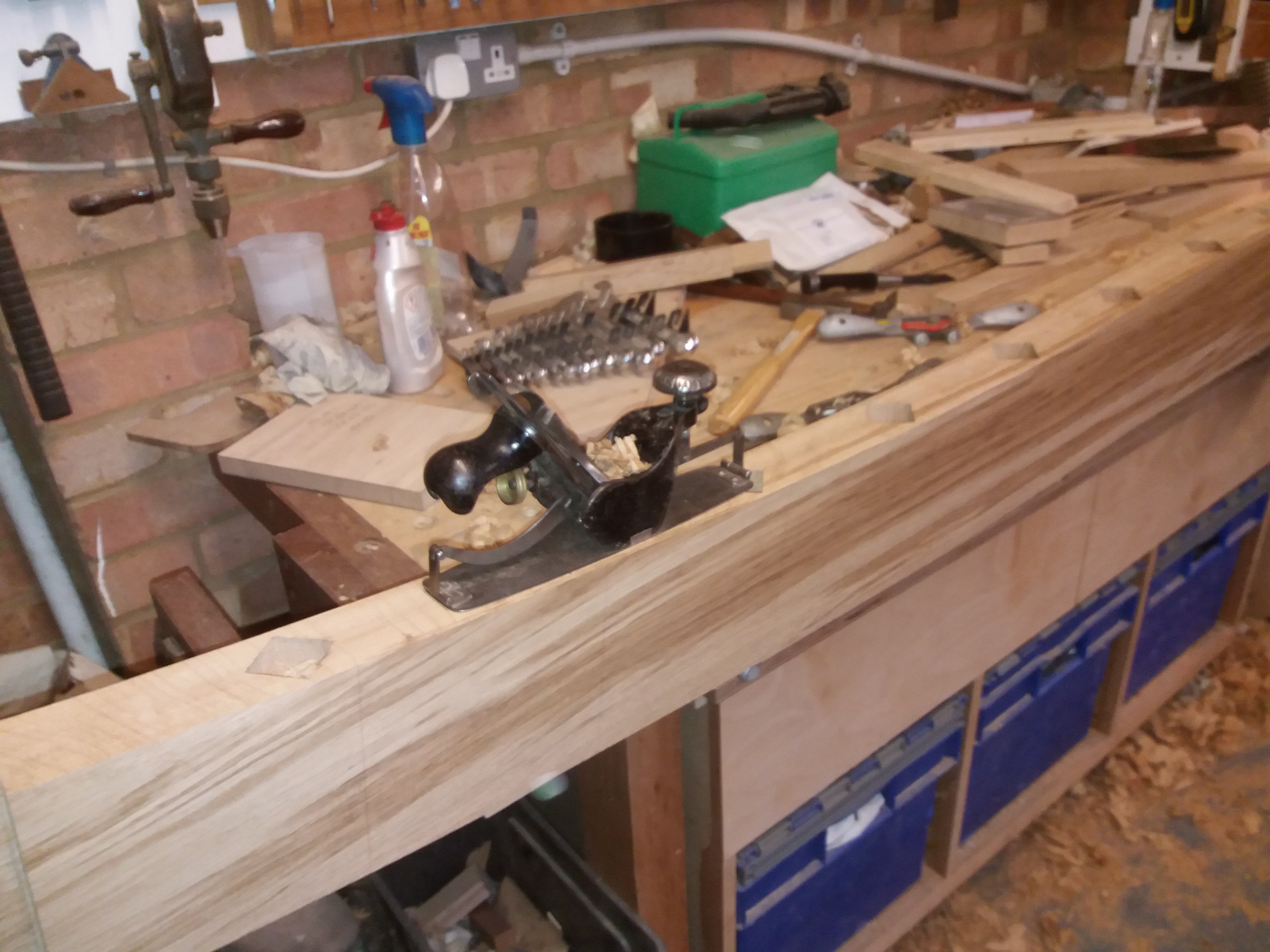
However for a couple of the pieces the table was not quite long enough with a jack plane being called into service to flatten the last 75mm
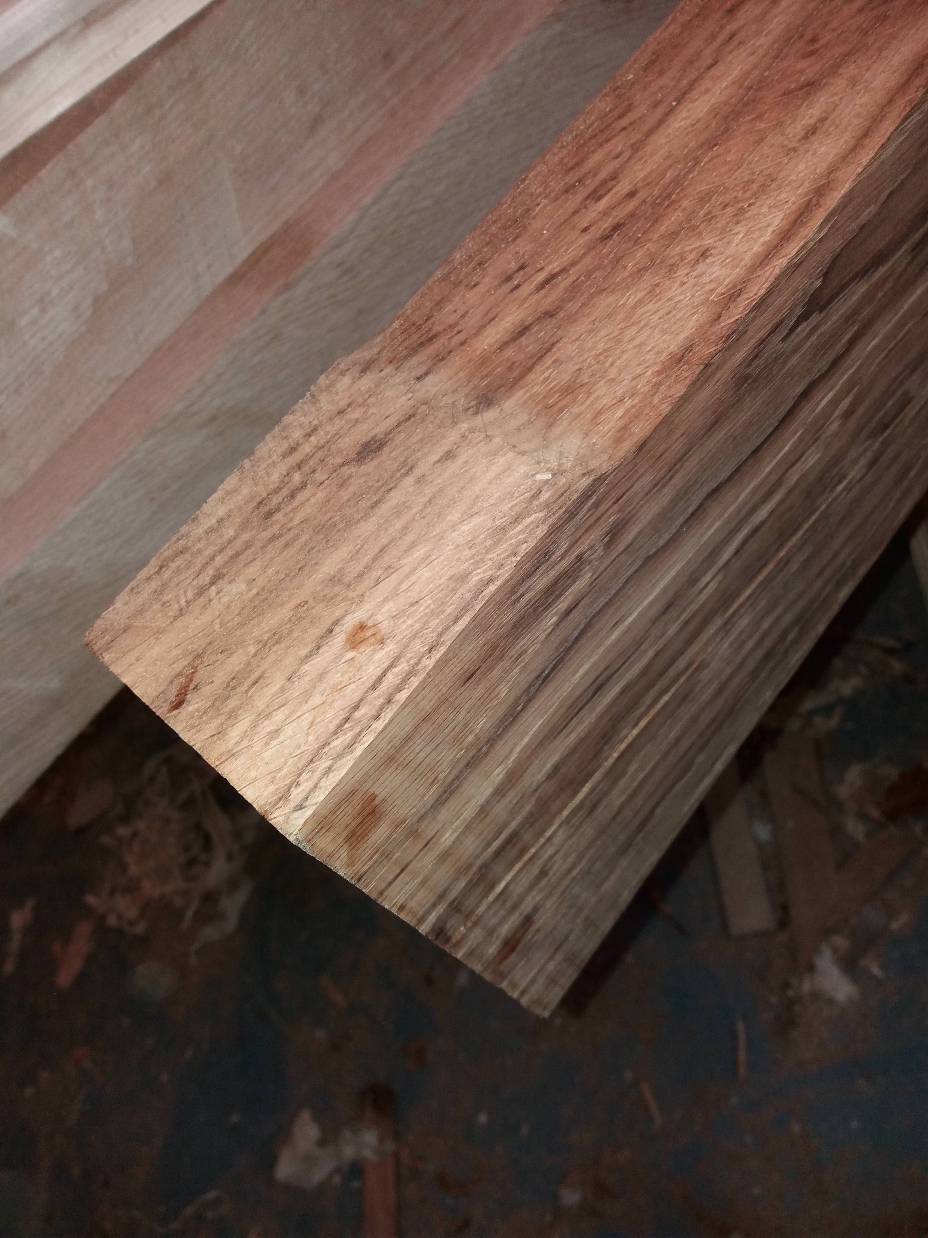
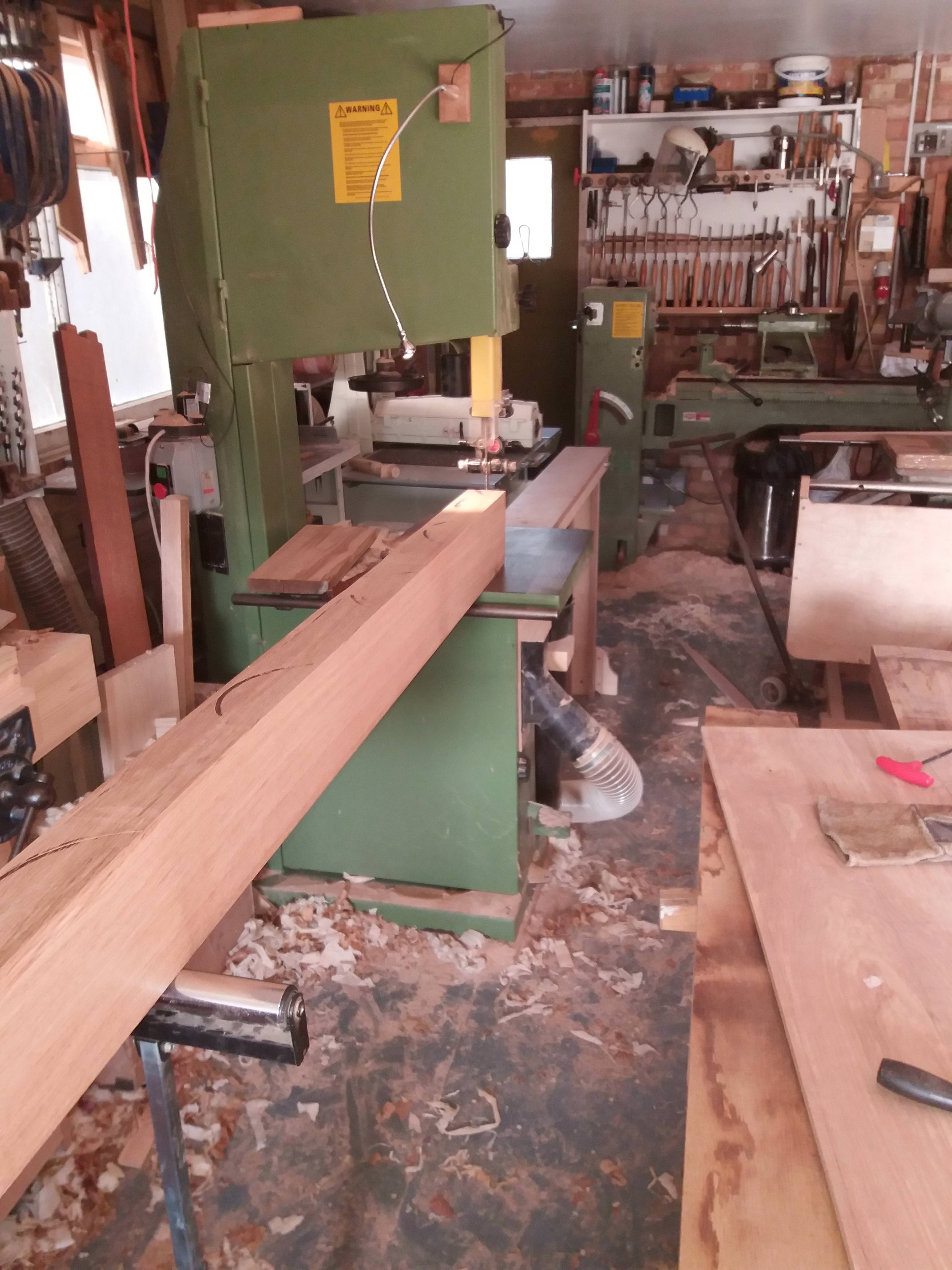
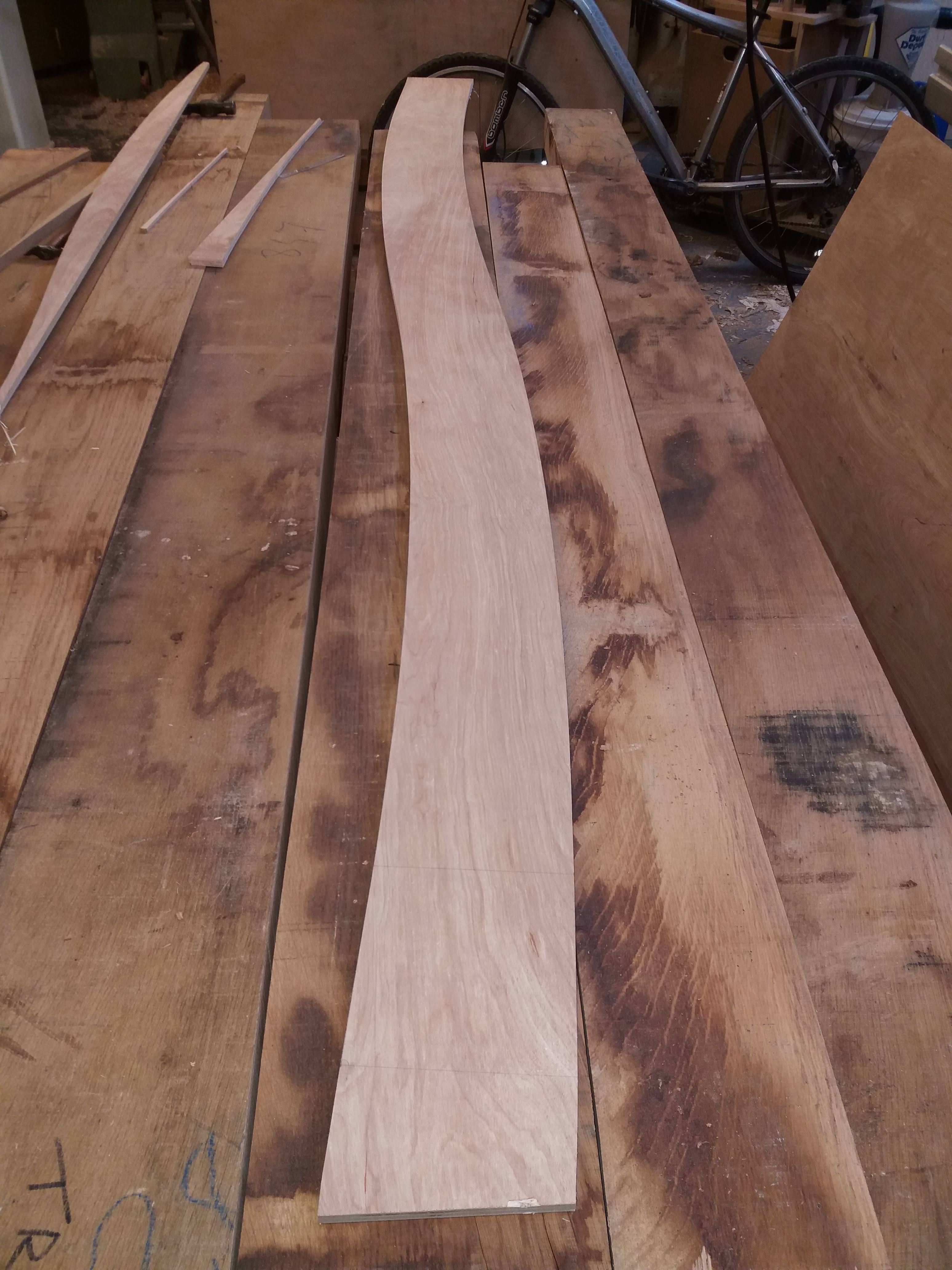
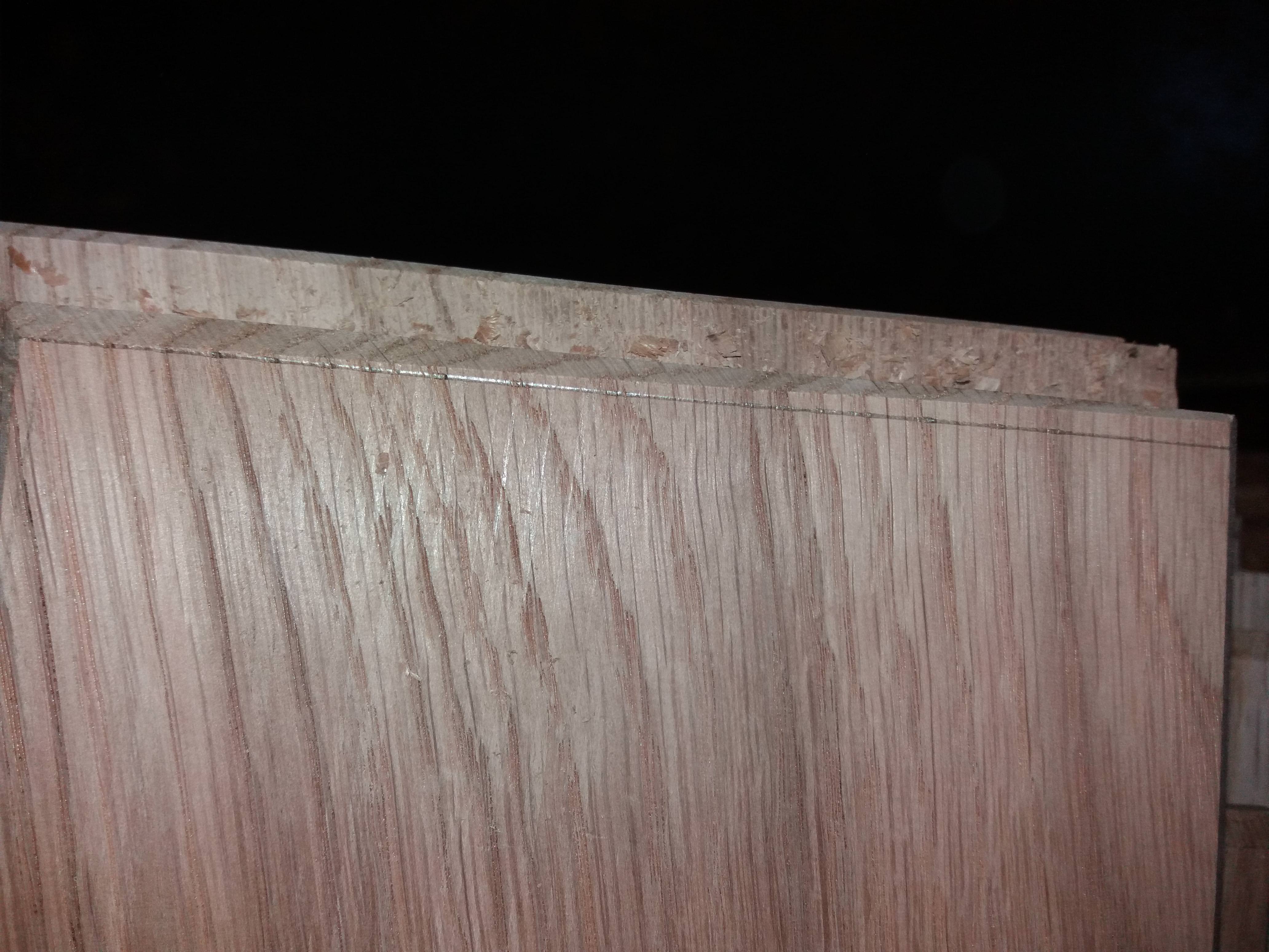
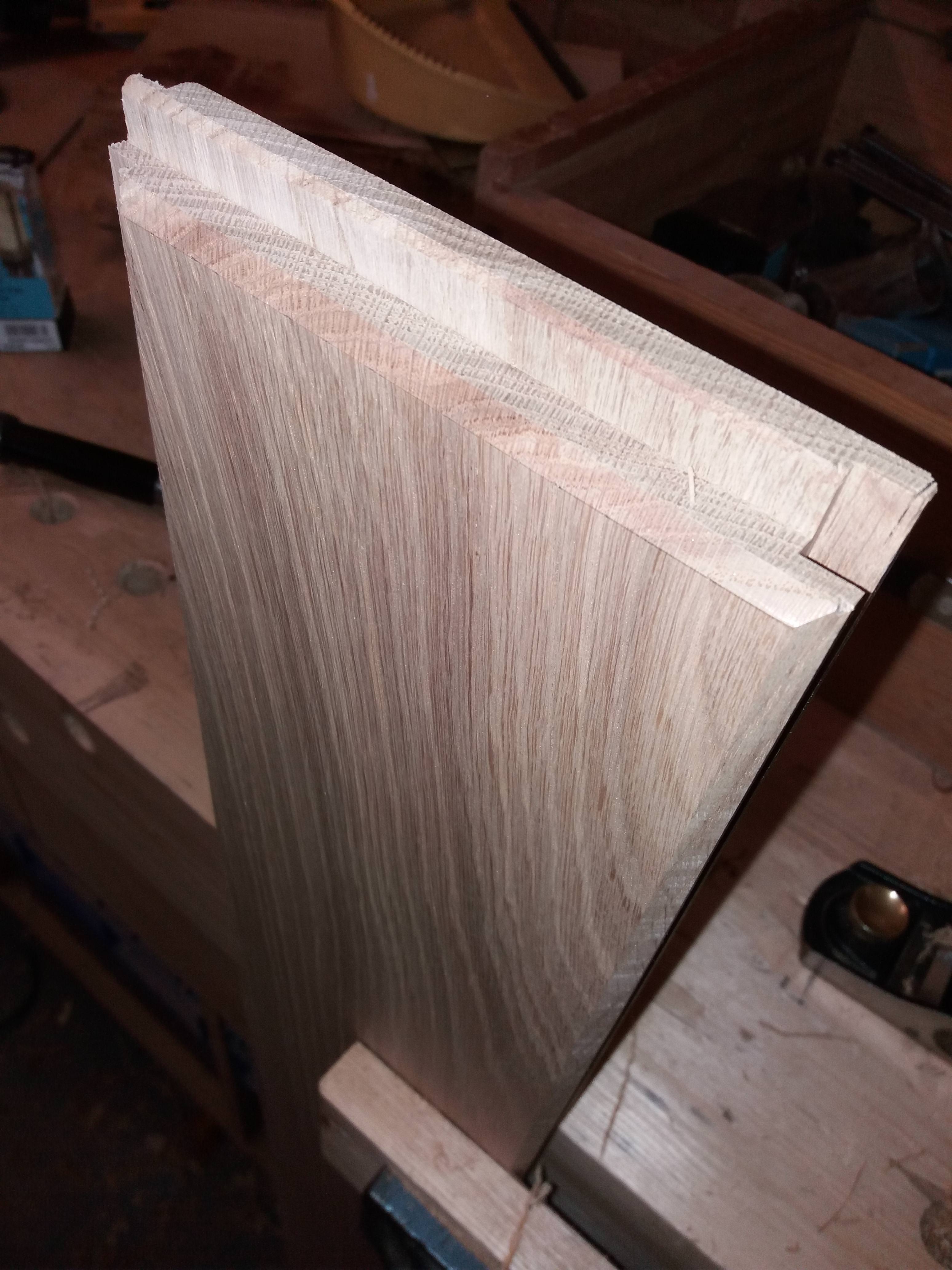
As this timber prior to preparing was between 80-85mm thick and my finish size was to be 60mm I didn’t want approx 20mm going up the dust chute as chippings. To solve this I purchased a m42 resaw blade from Ian at tuffsaws which left me with some lovely 15mm+ stock, much of it quarter sawn to use for drawer sides boxes etc.
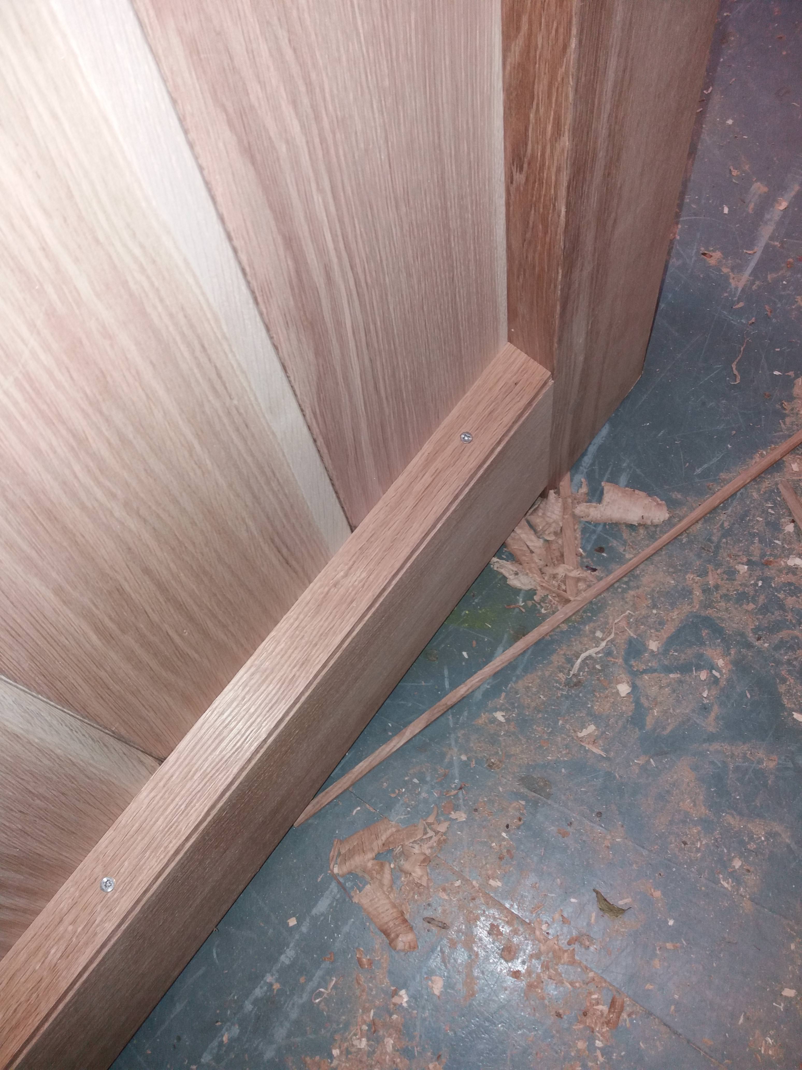
In addition the bottom rail was to be a barefaced rail to which I could just get two out of one piece of 80mm (it was actually about 87mm). The table support I used on the planer also came into service again.
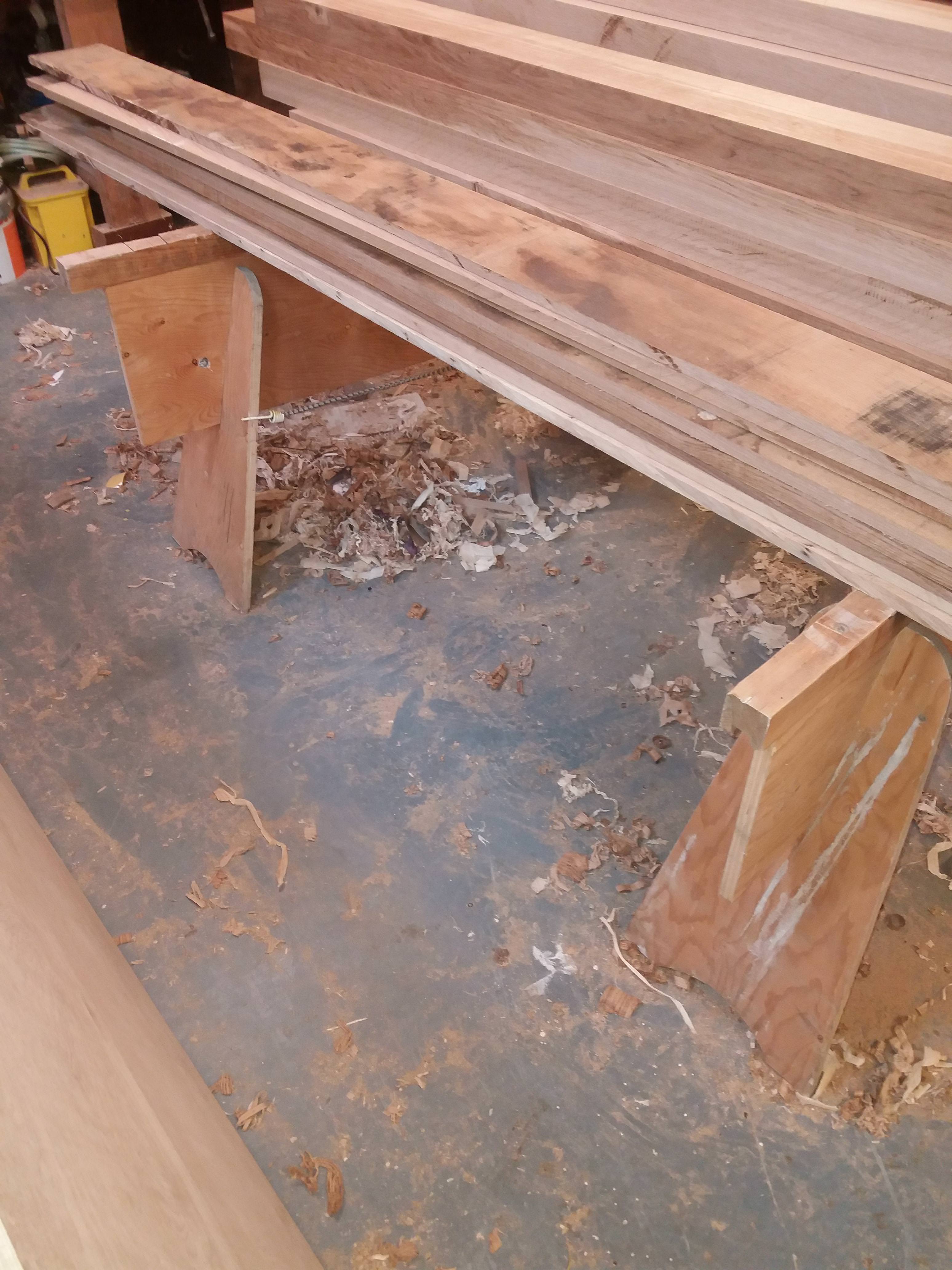
The rippings
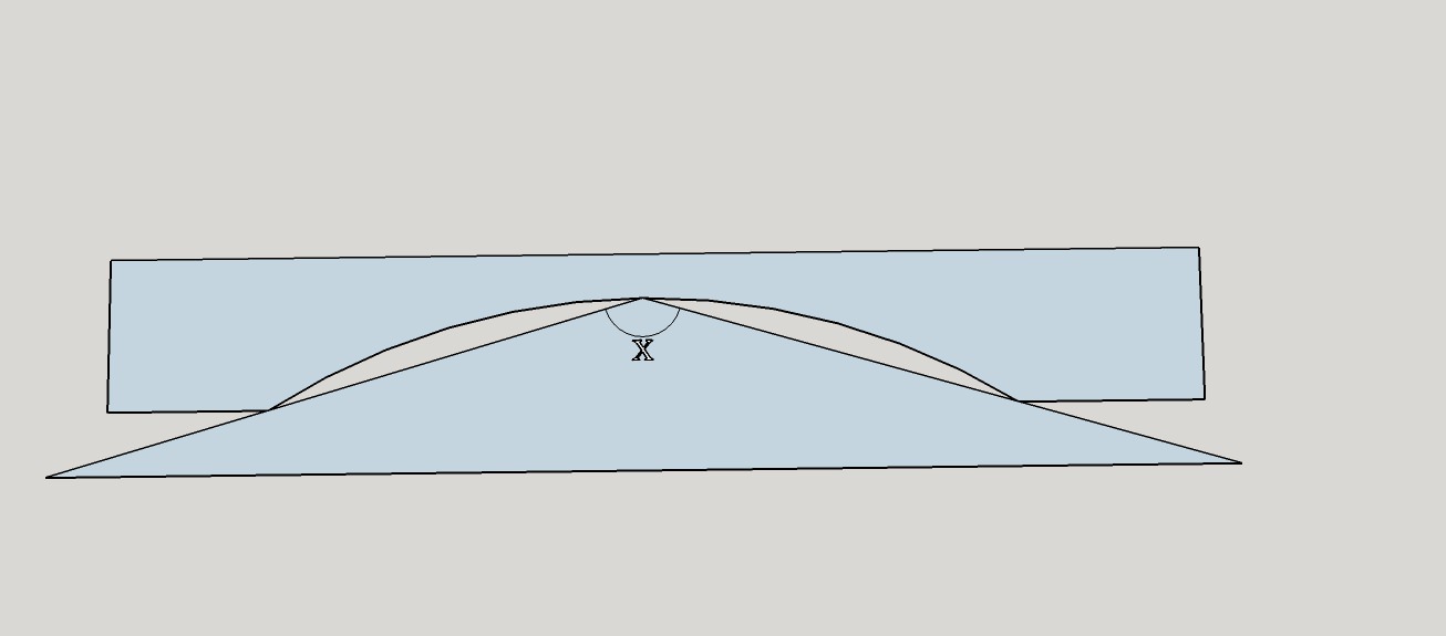
The top half of the gate was set out on a board full size, to set out the curves on the top rail if I were to use trammels I would have needed a radius of approx 5m which was not doable. I considered a bendy lath but considered this not accurate enough. Therefore I employed a process I have used in the past to set out large but shallow bow windows. It’s called a camber slip and exploits the fact that the angle in an arc remains constant (could explain it better but this might help, angle X remains constant as it moves round the arc)
The process as used by myself using a couple of pins in the setting out board
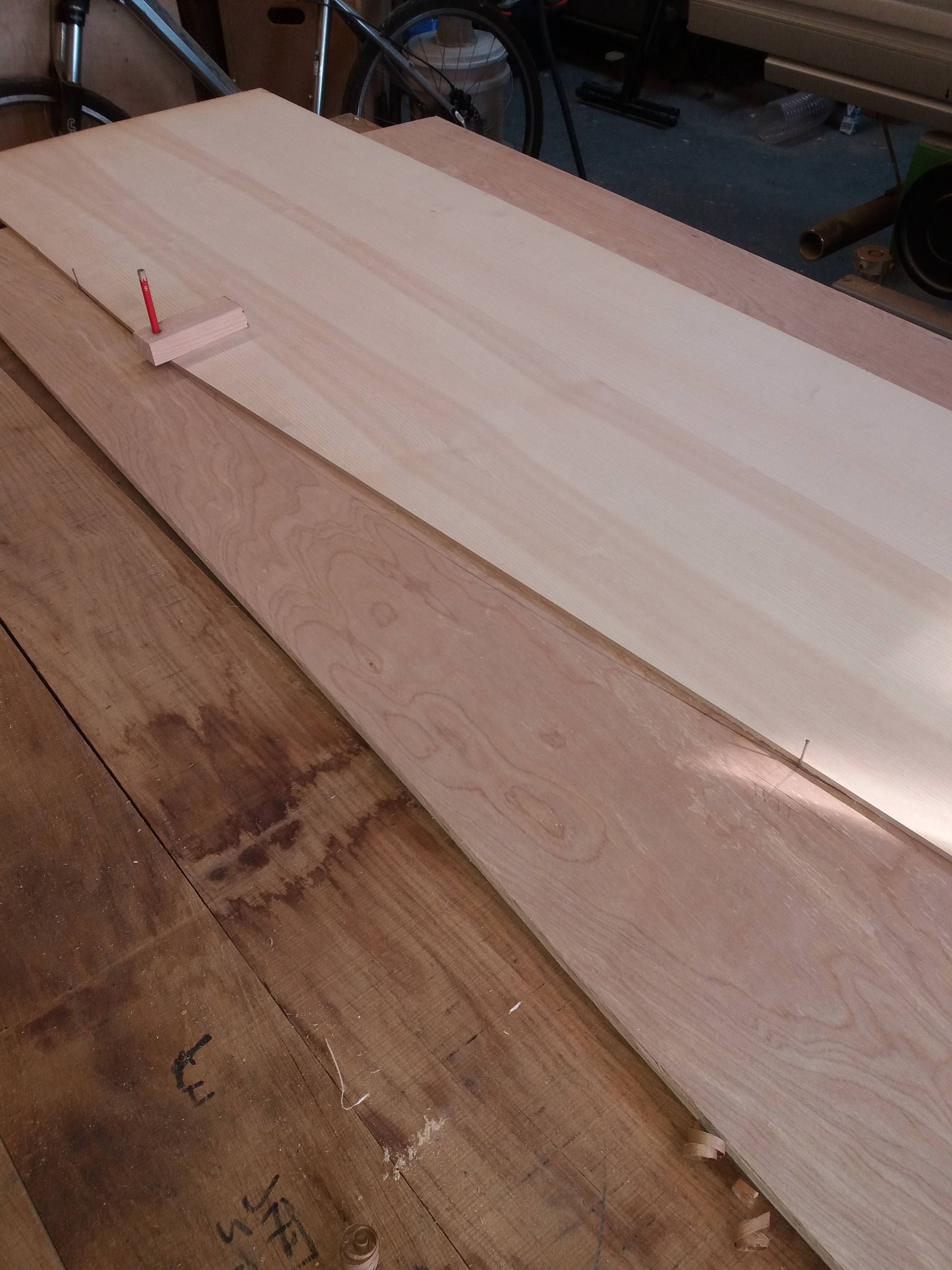
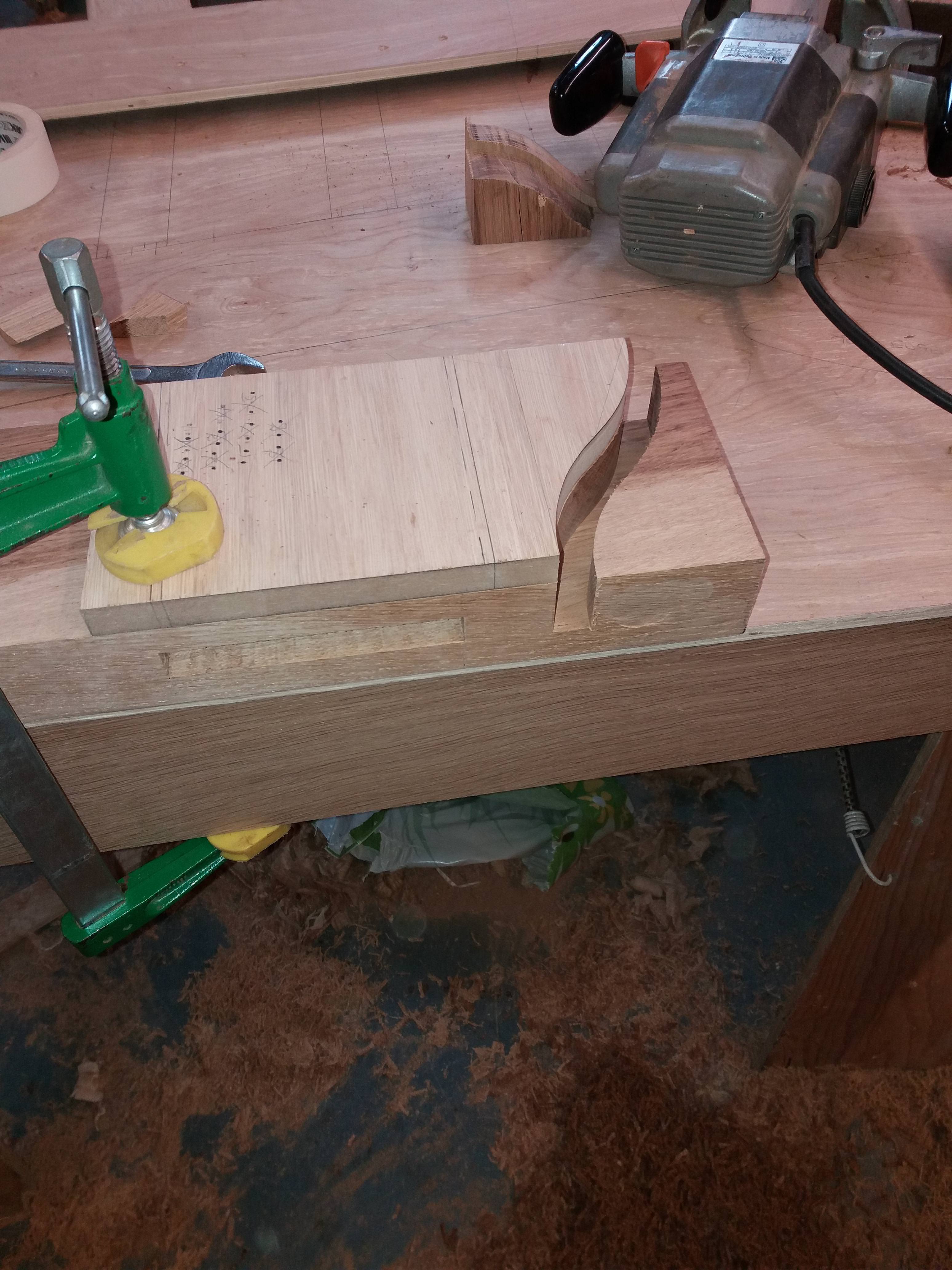
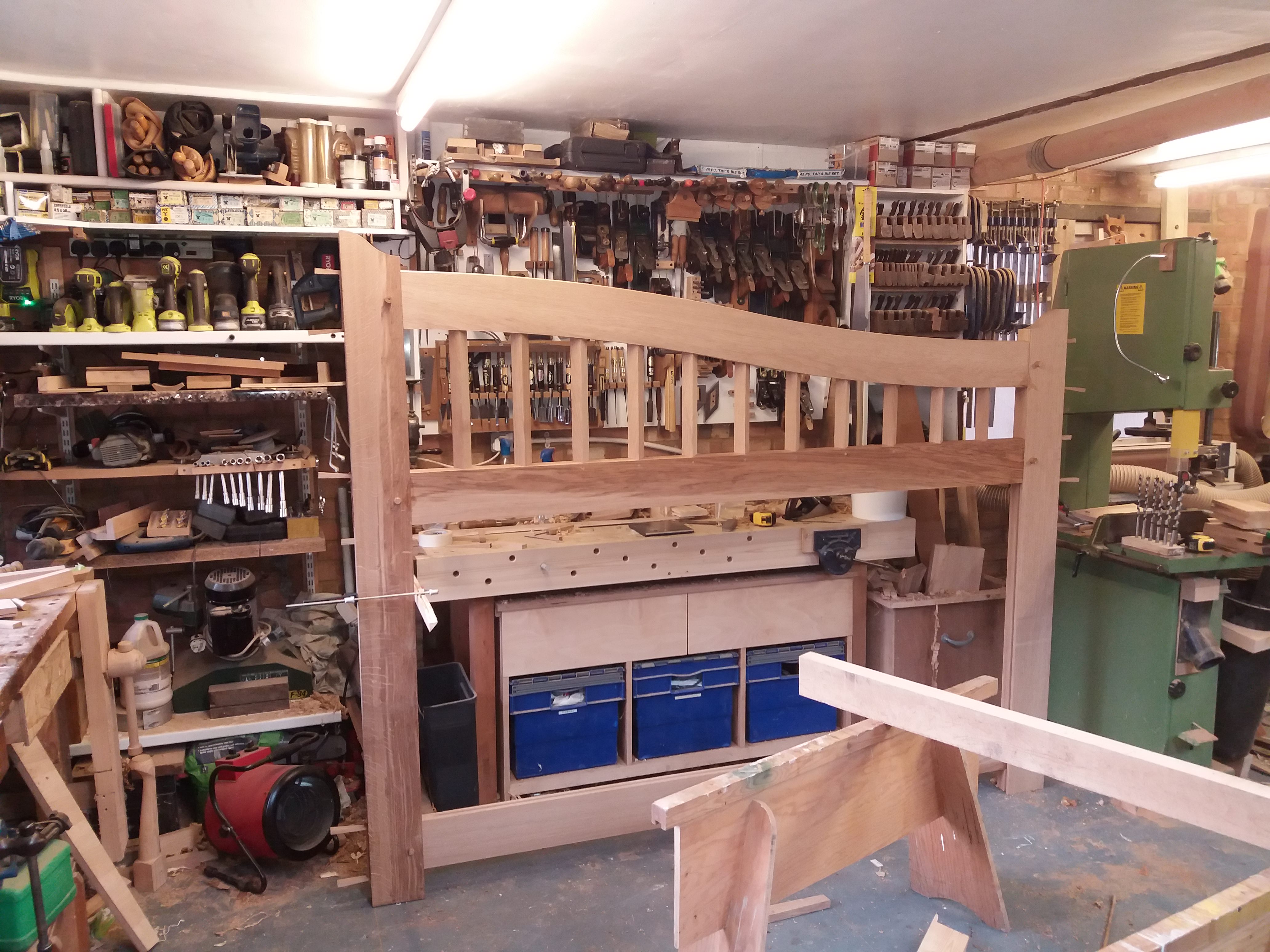
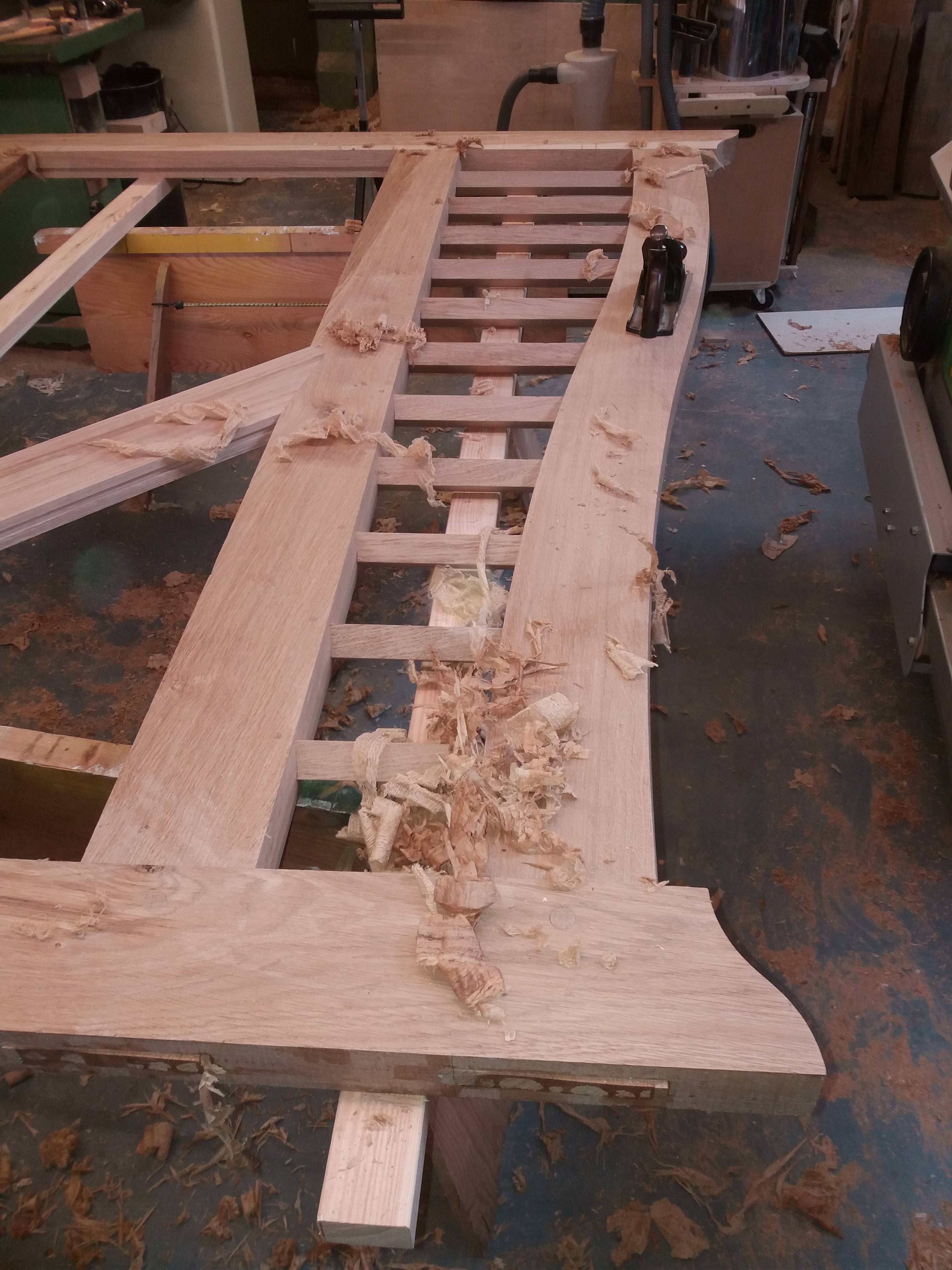
Eventually I was able to produce a full-size template of the top rail
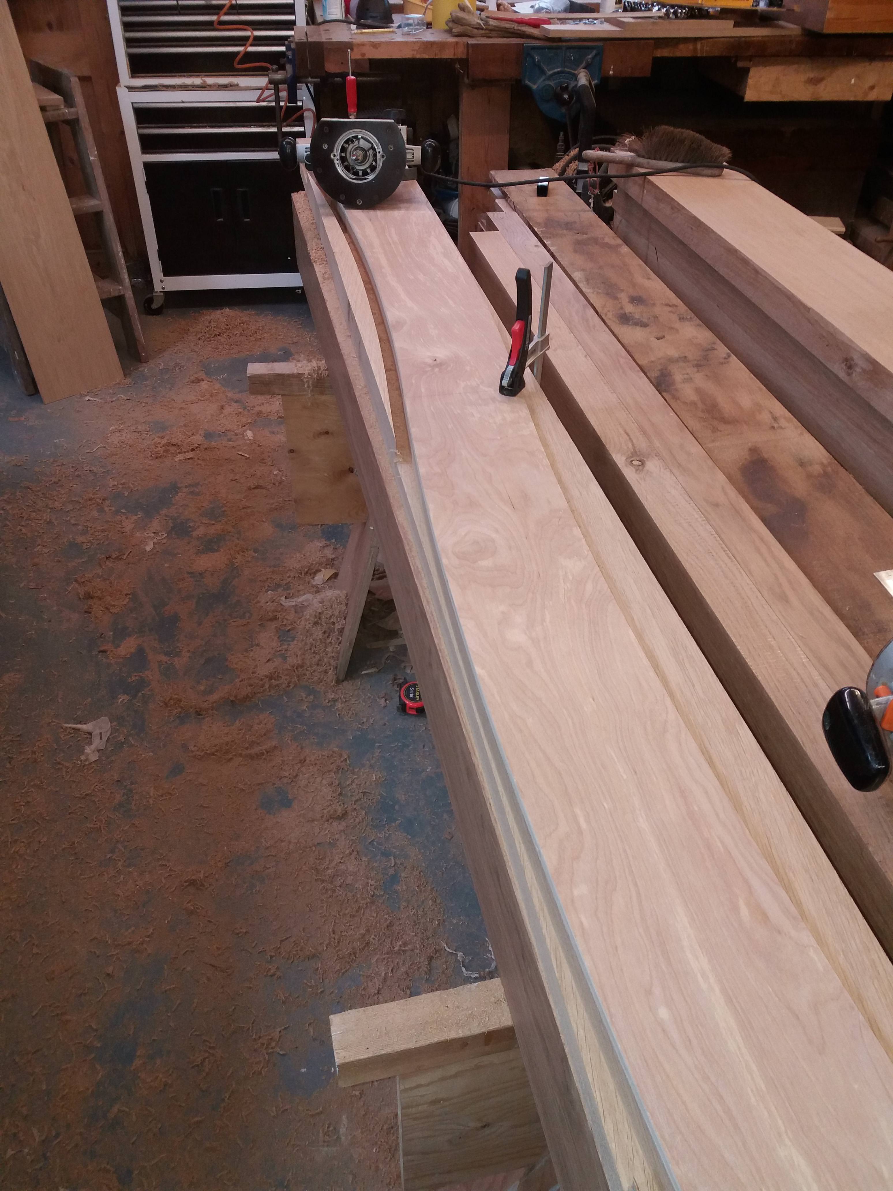
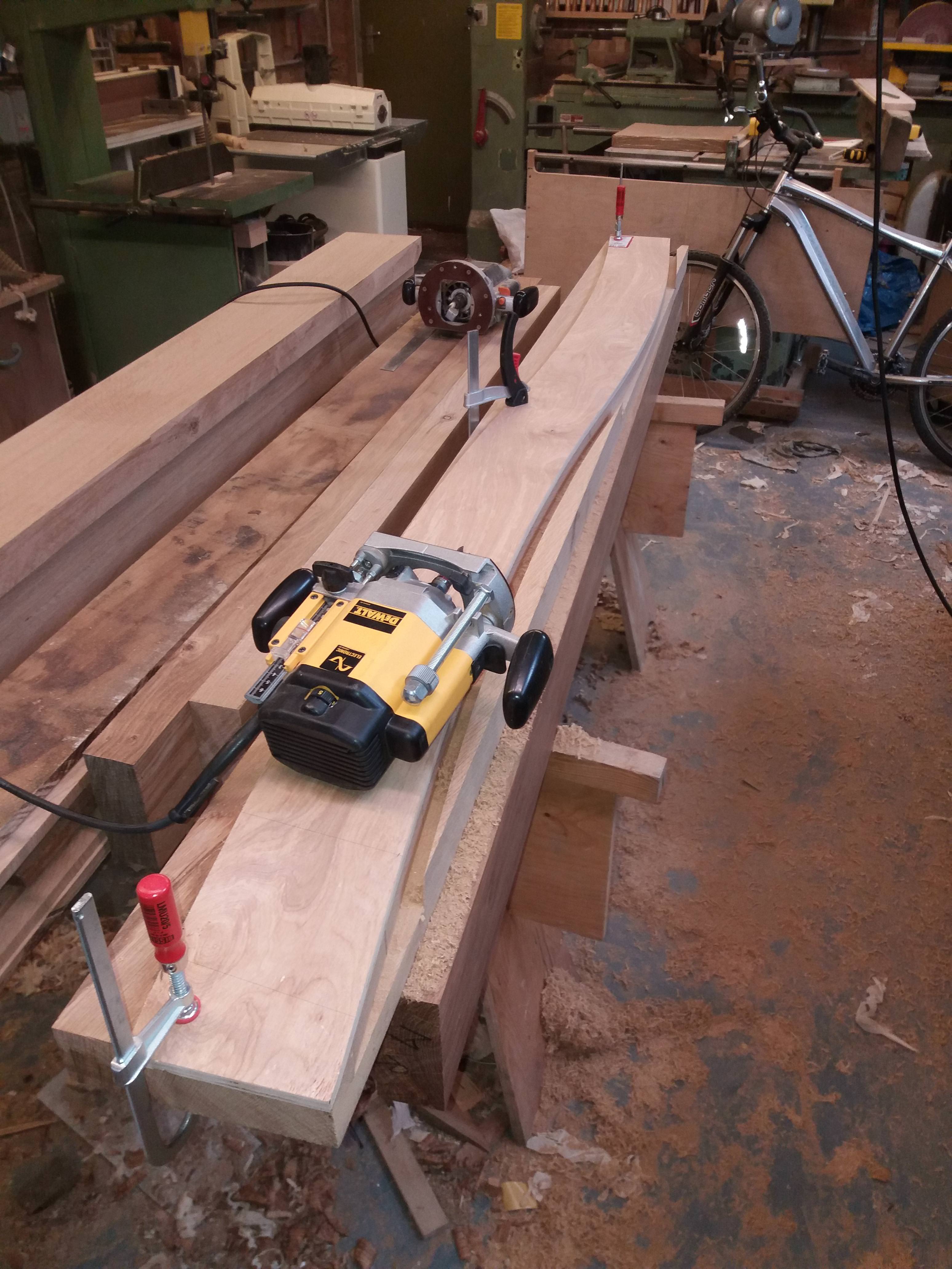
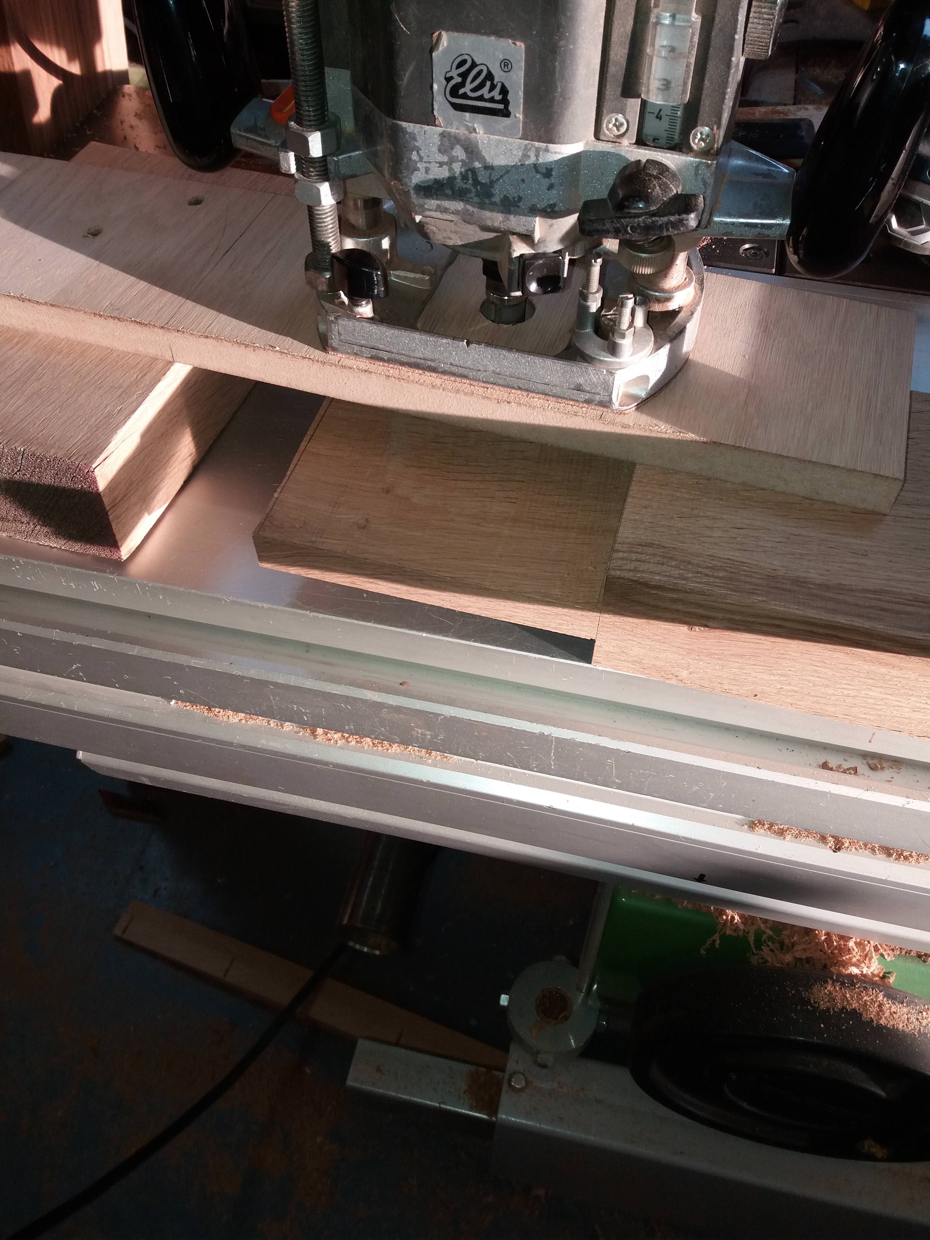
And used it as a template for a router and bearing cutter to shape the top rail.
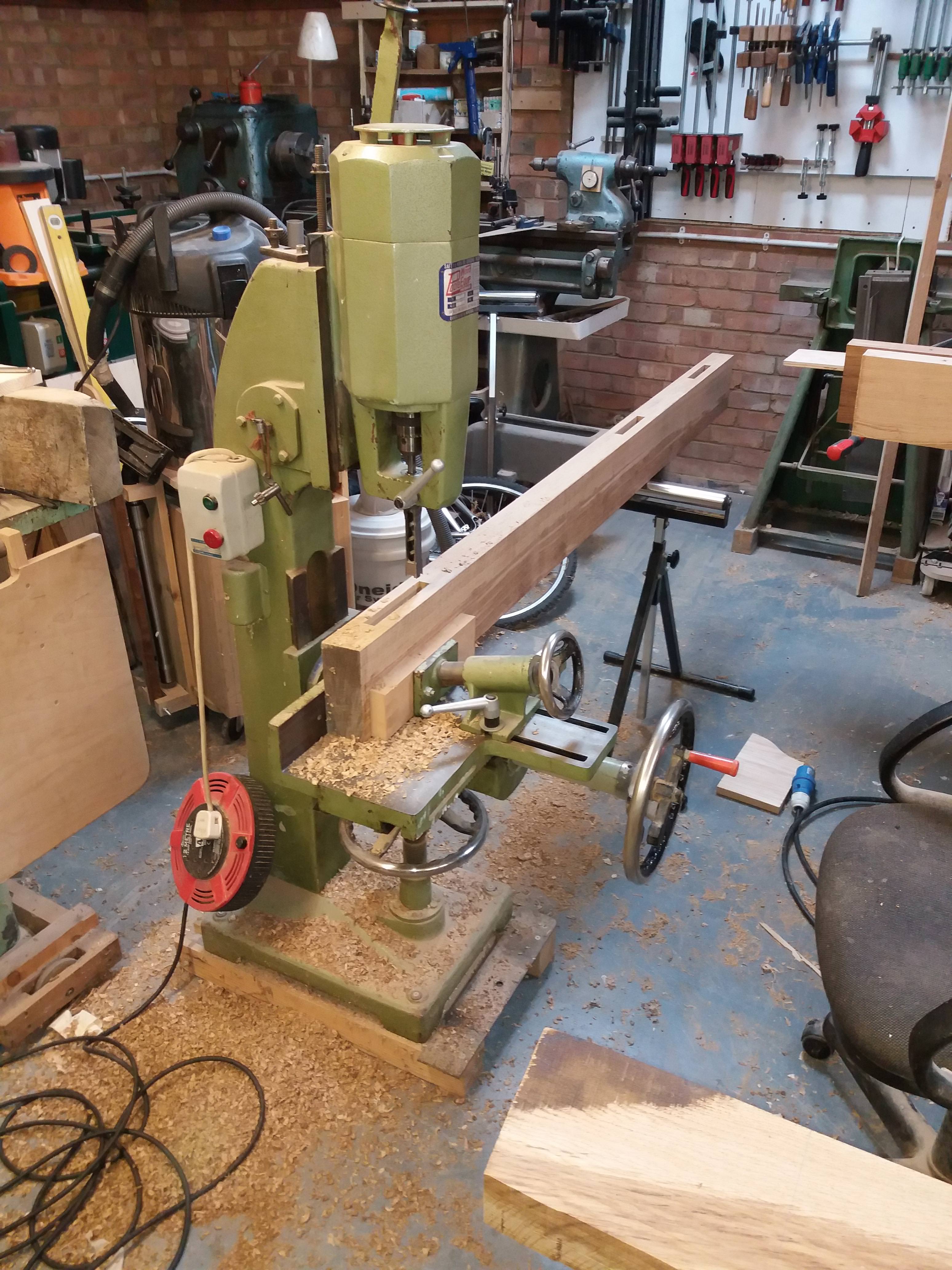
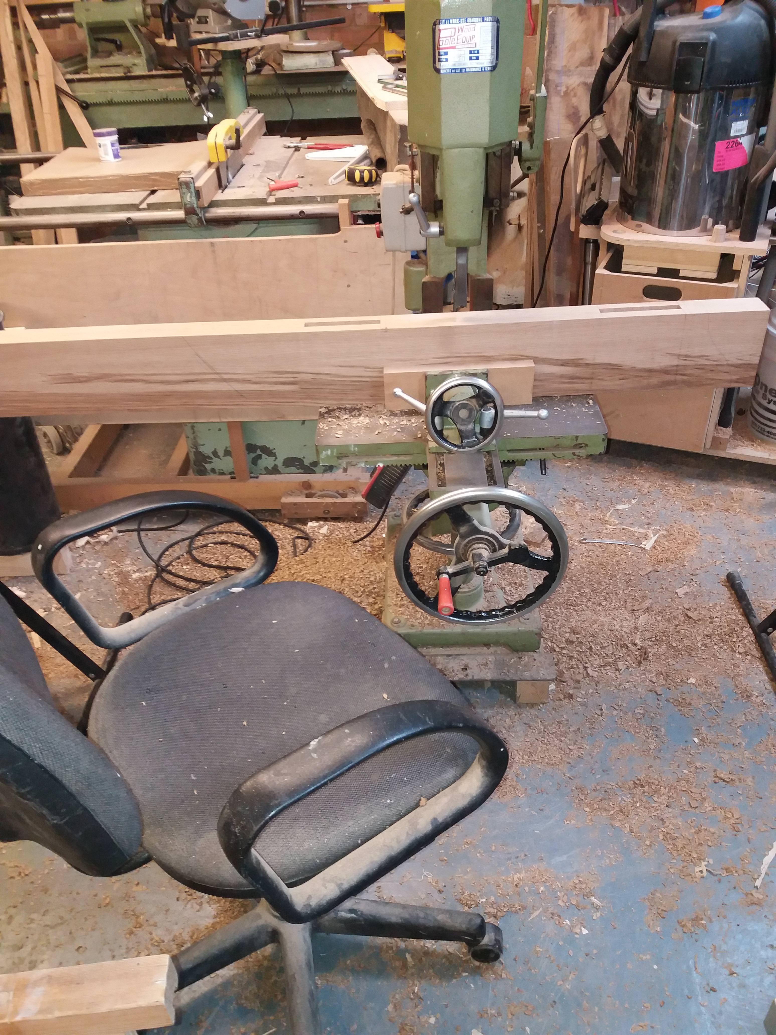
Everything else was set out from the rod and morticed
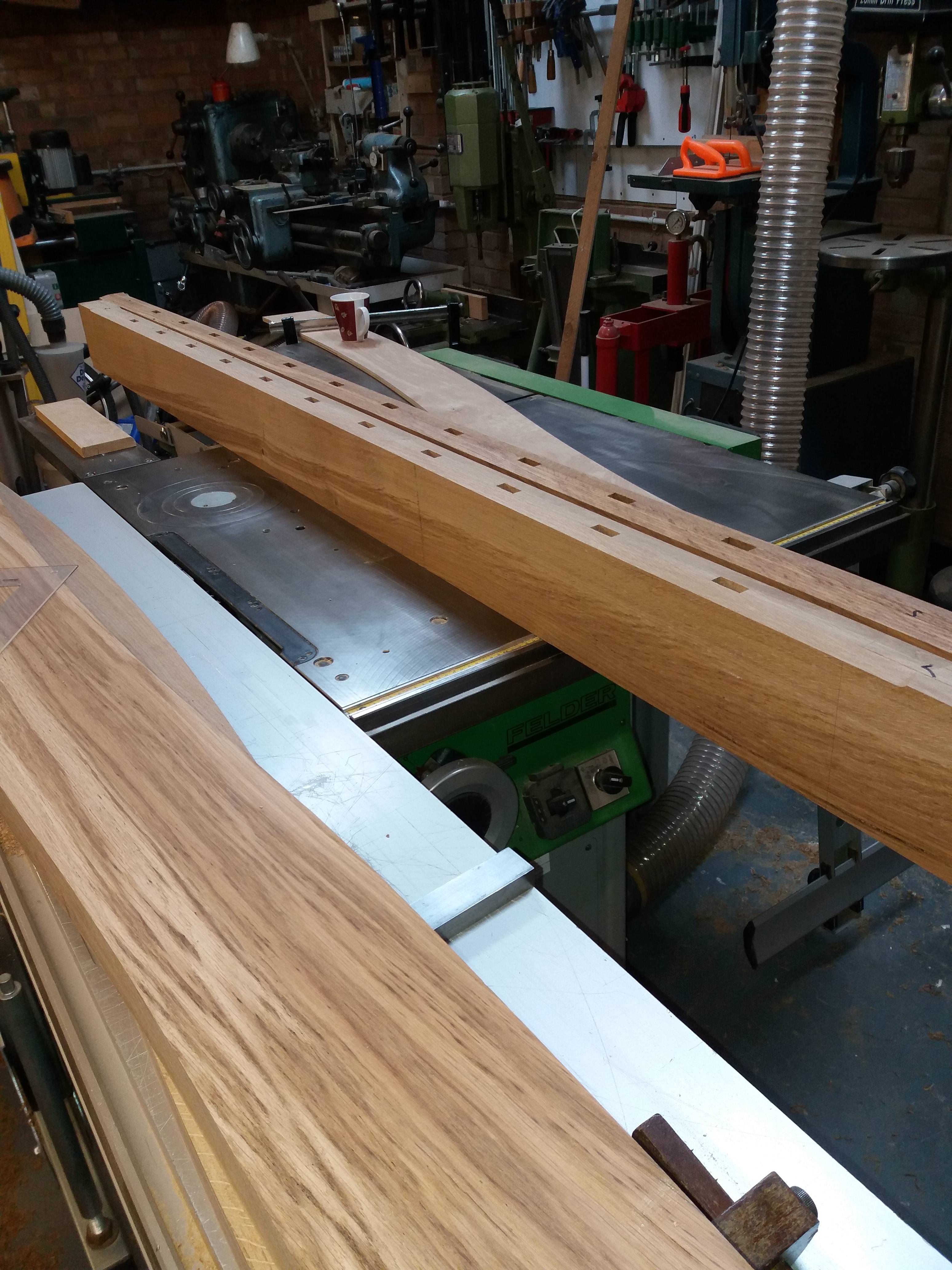
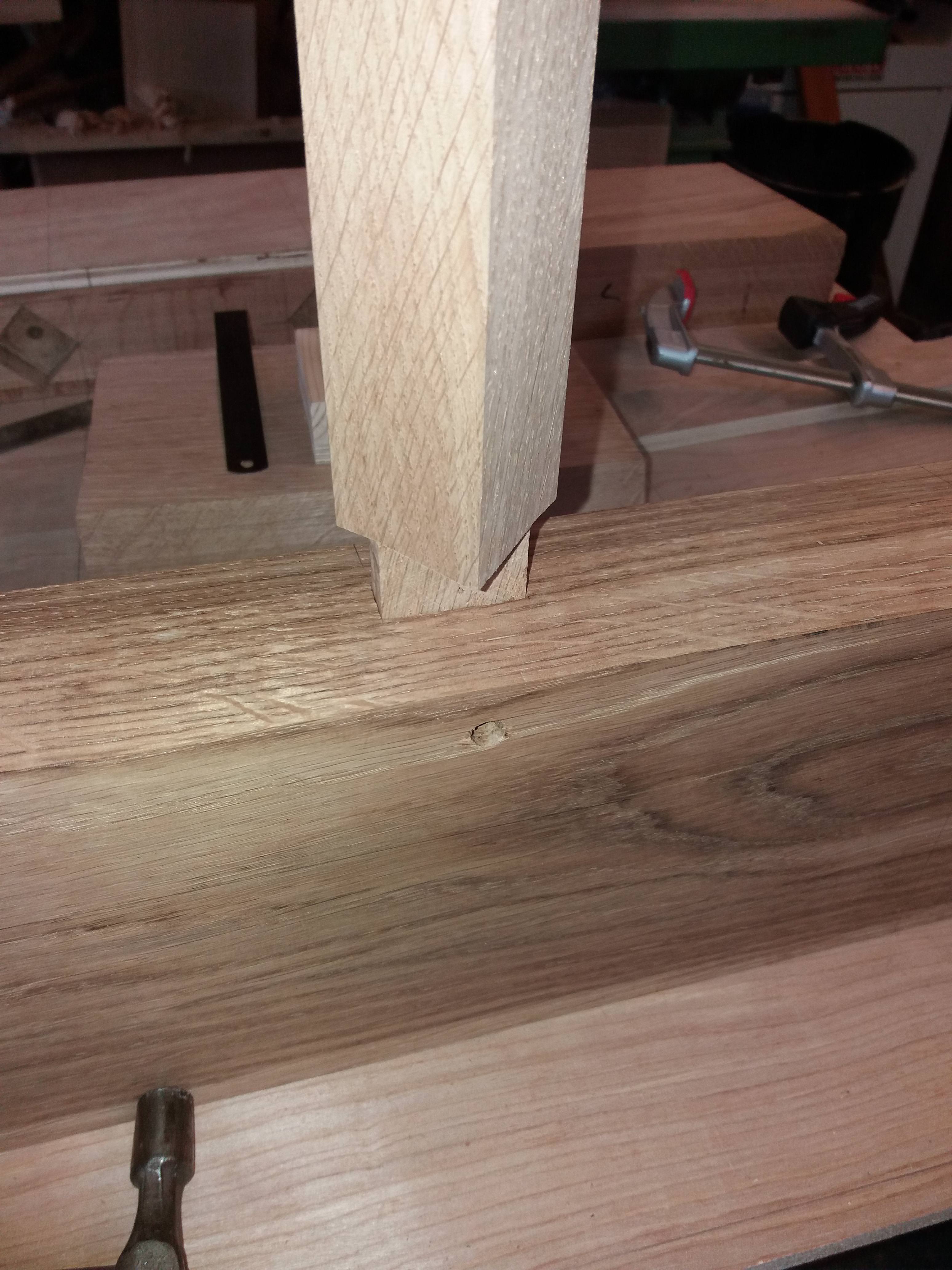
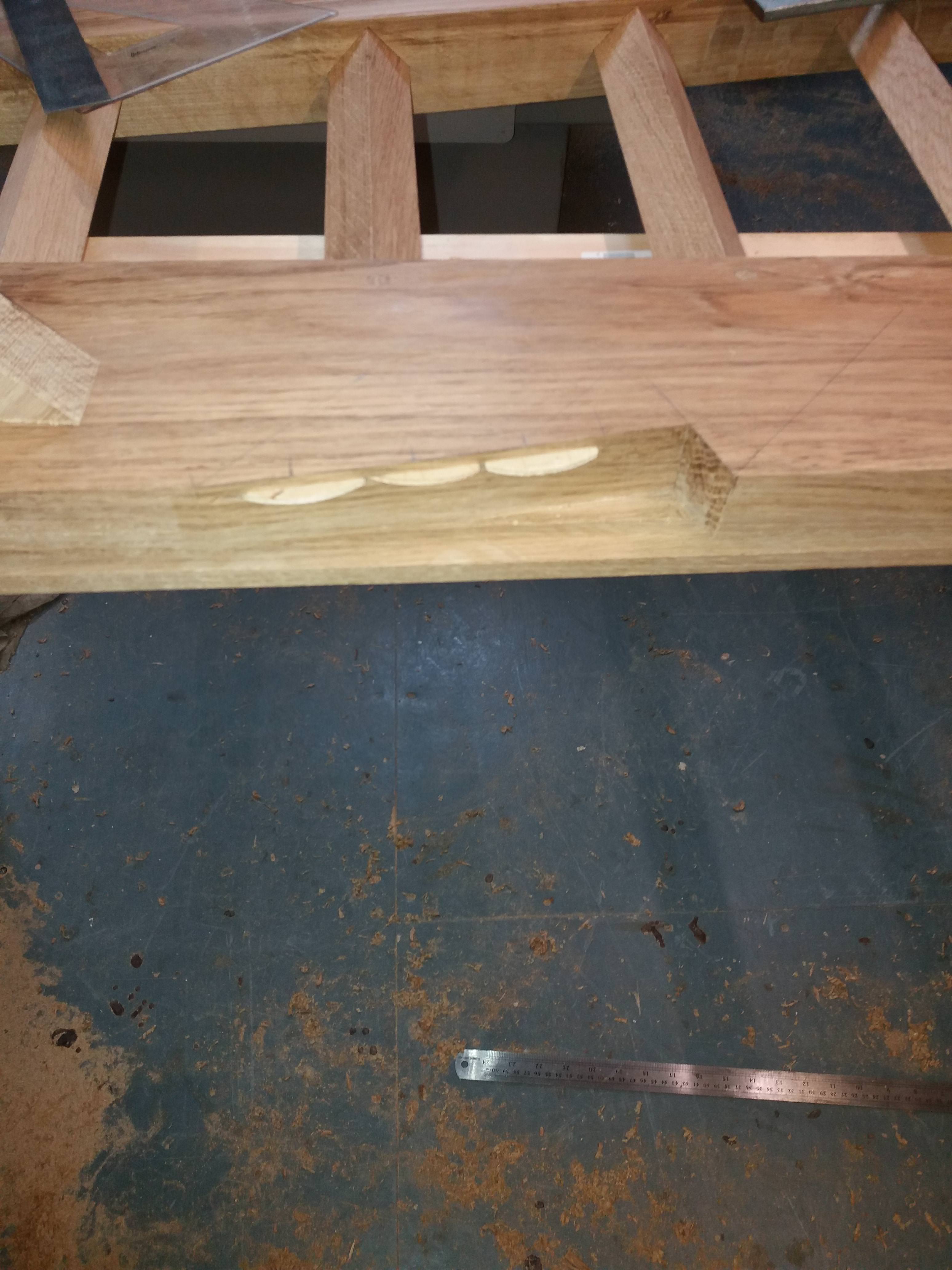
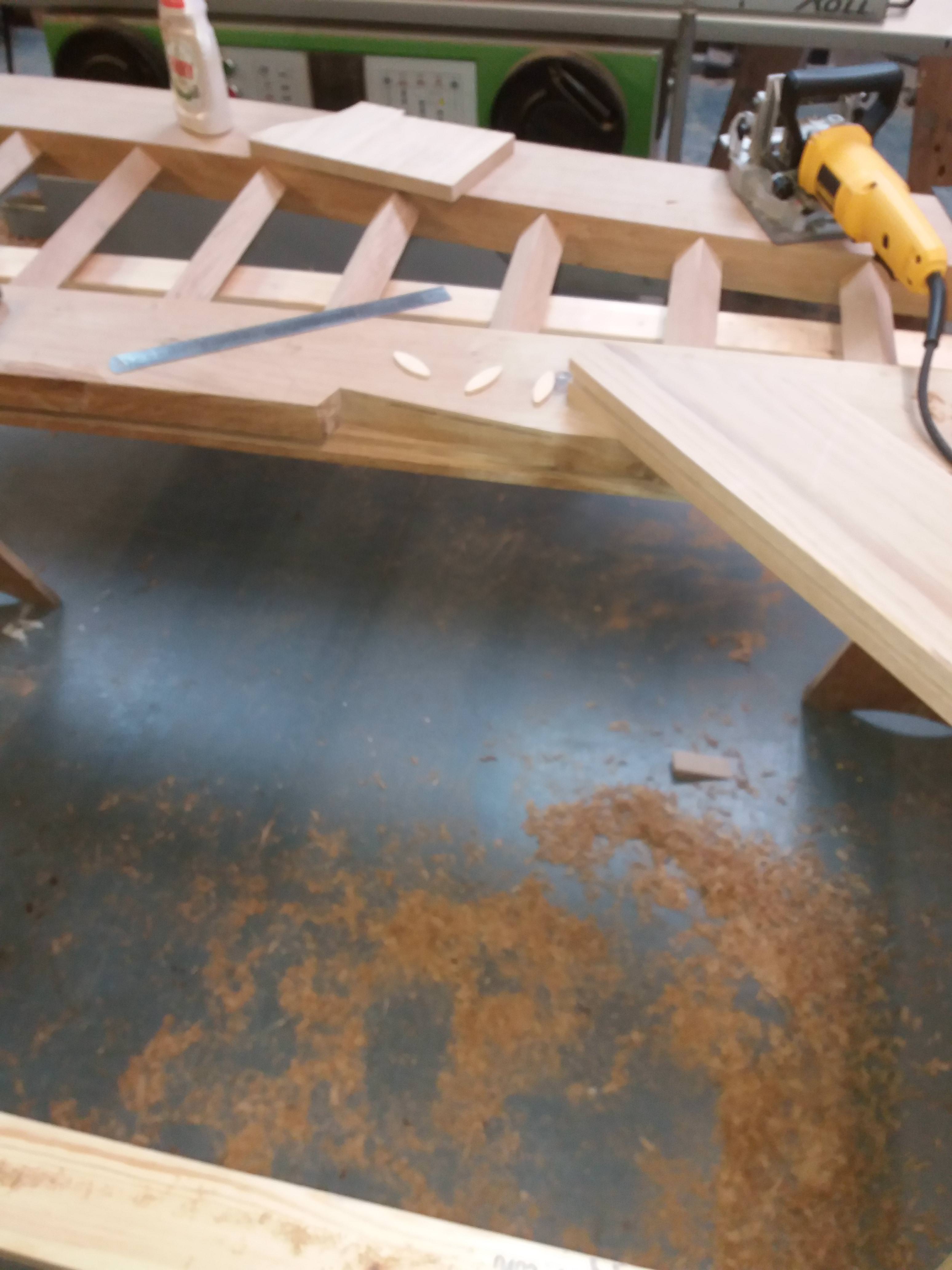
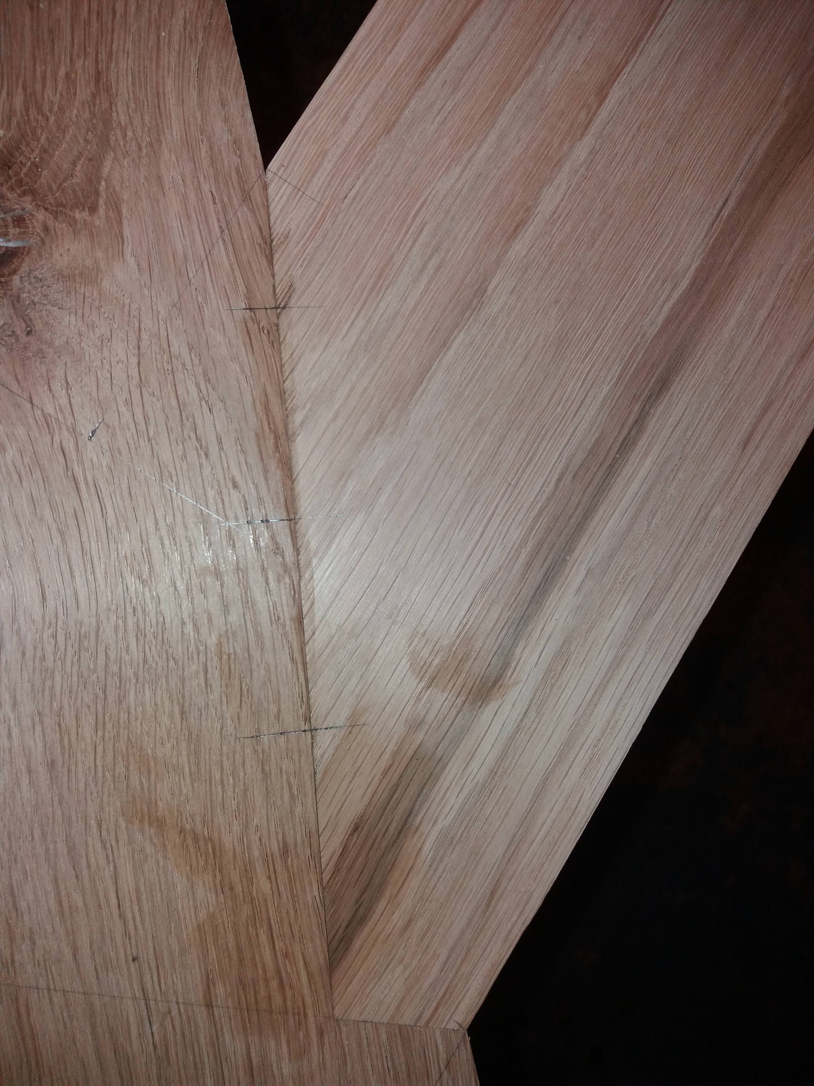
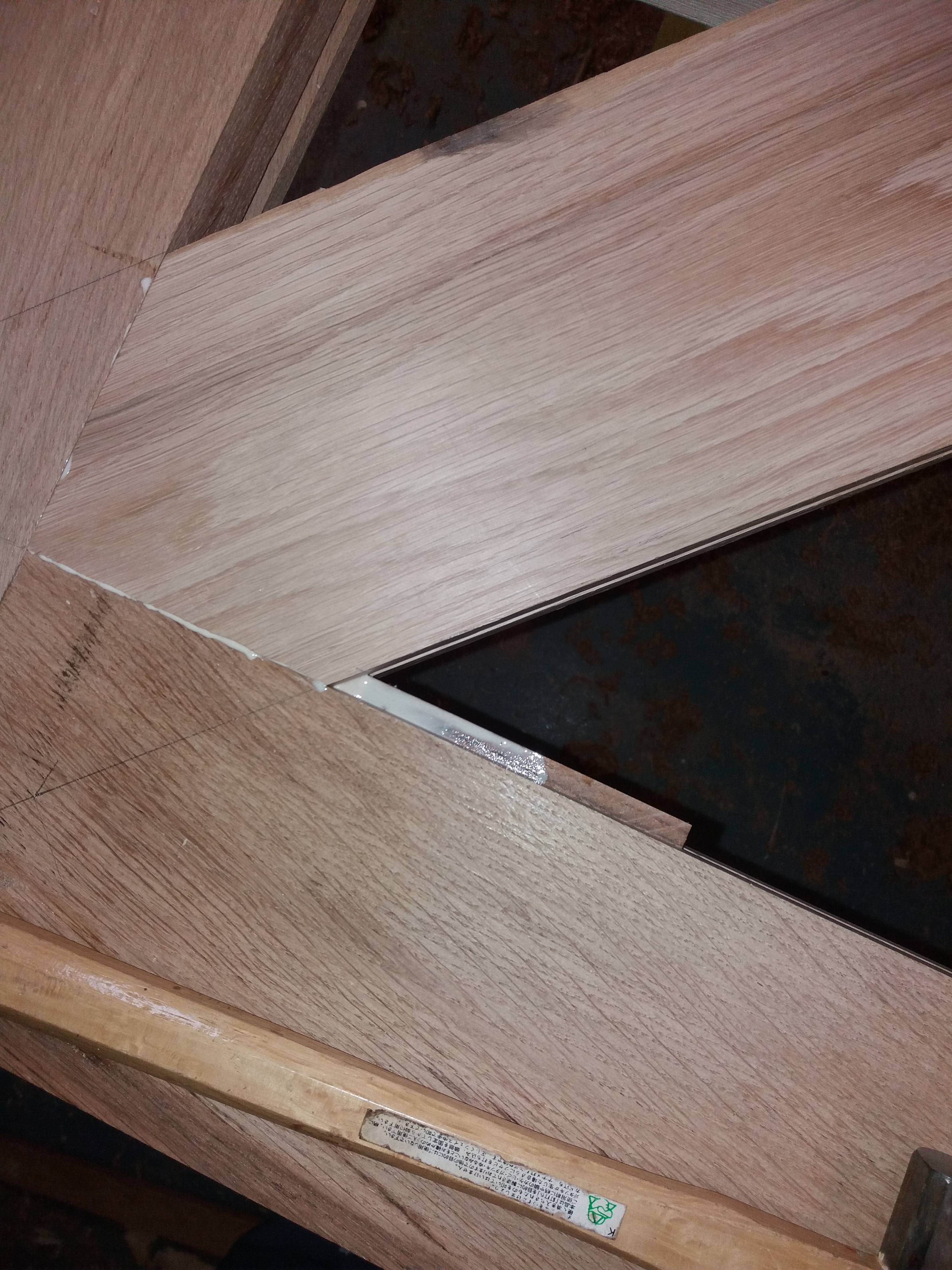
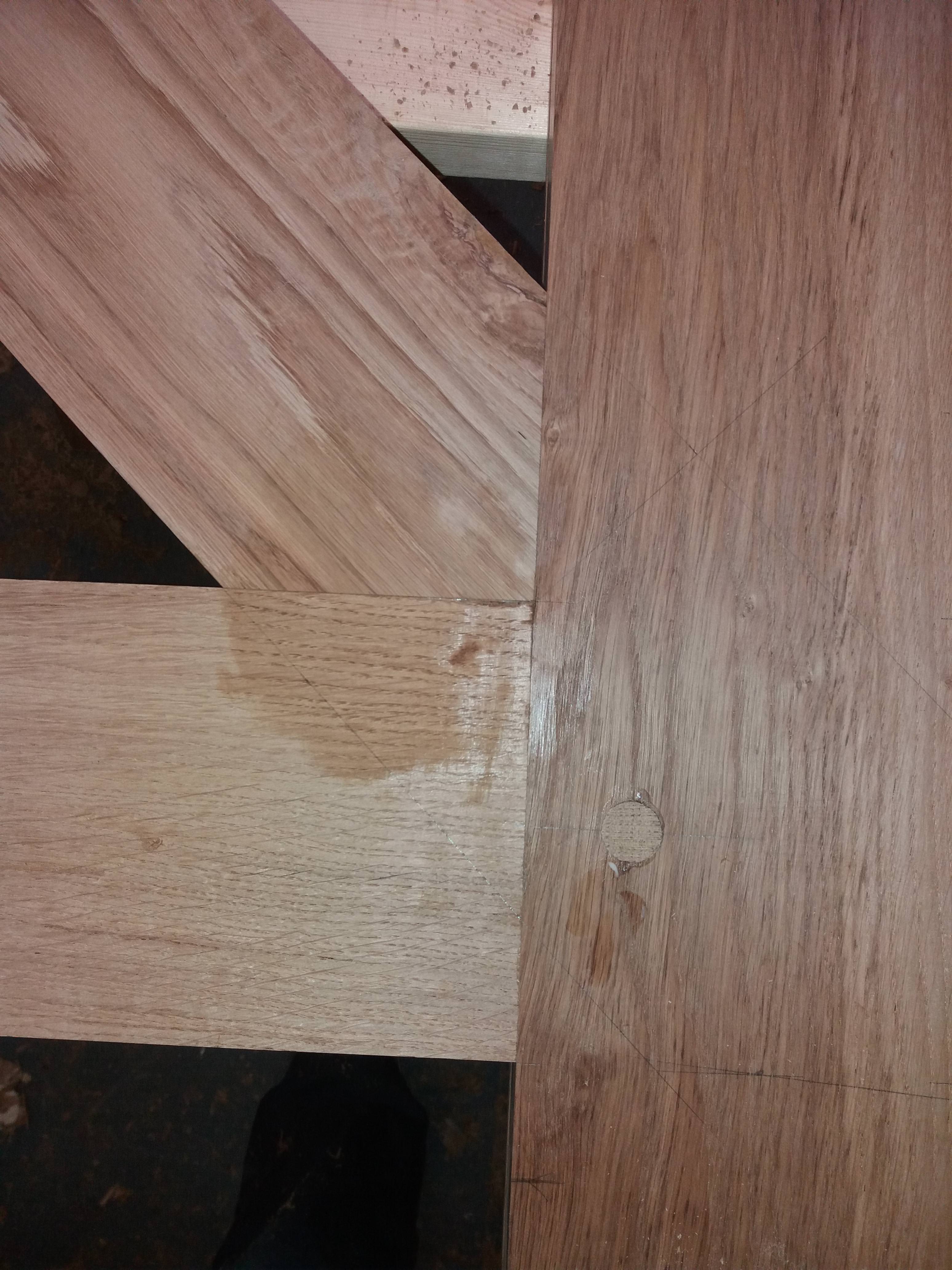
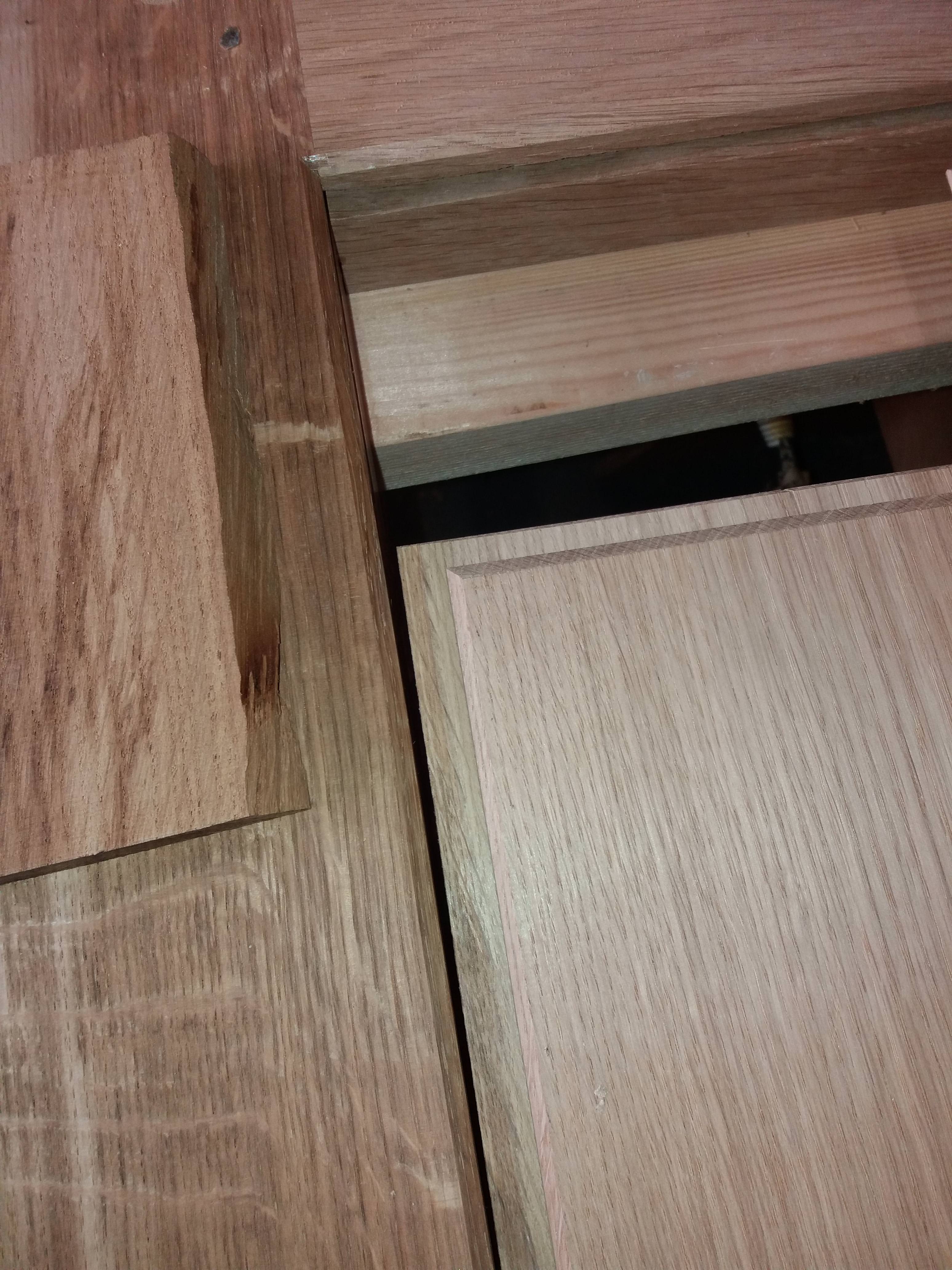
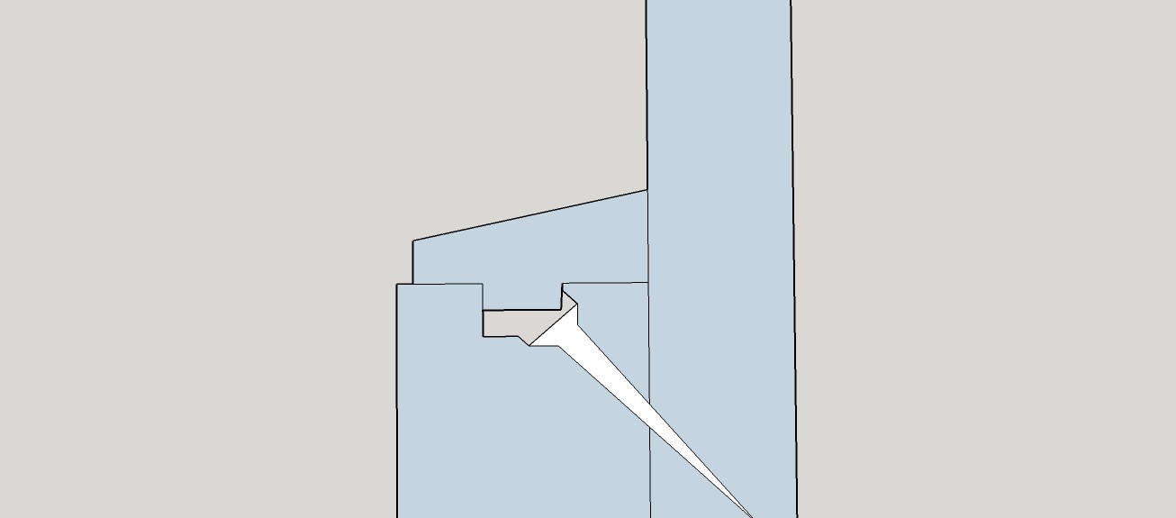
Timbers were to be morticed into the top section at a 45 degree angle but prior to this the top edges of the middle and top rail were bevelled to prevent water retention I will hope the photo’s will show how I cut the tenons on the above mentioned timbers.
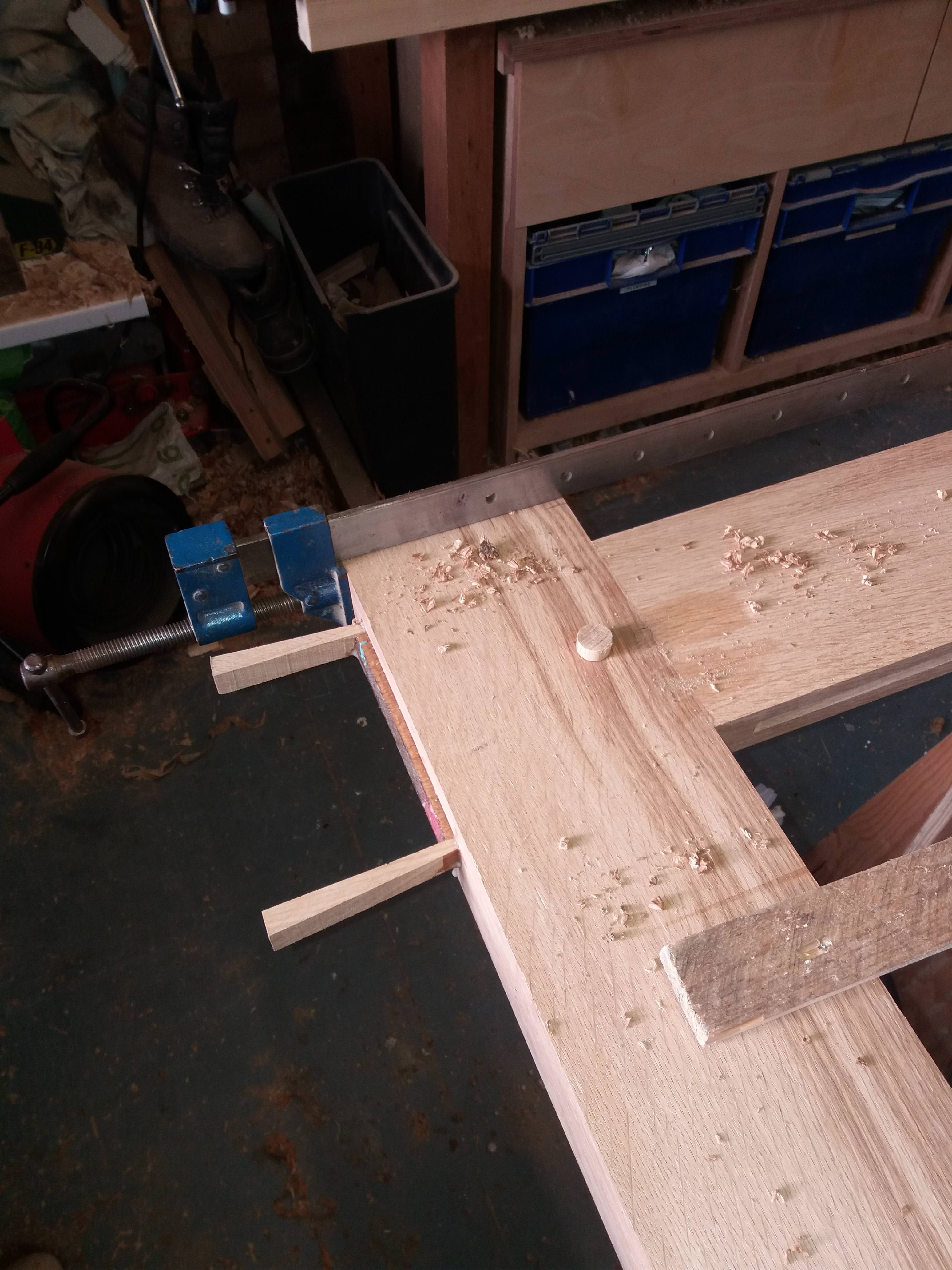
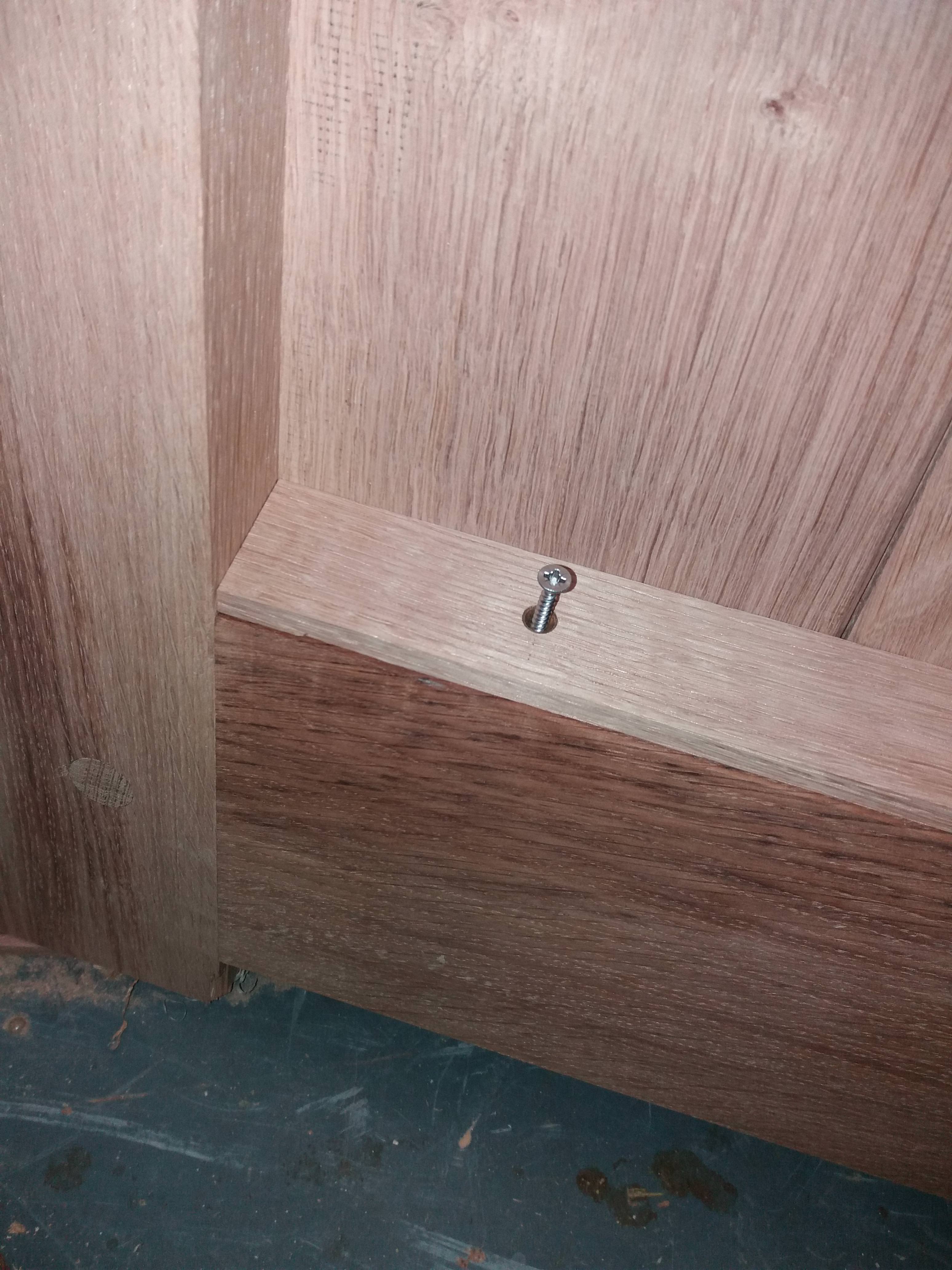
These were draw dowelled into the middle rail
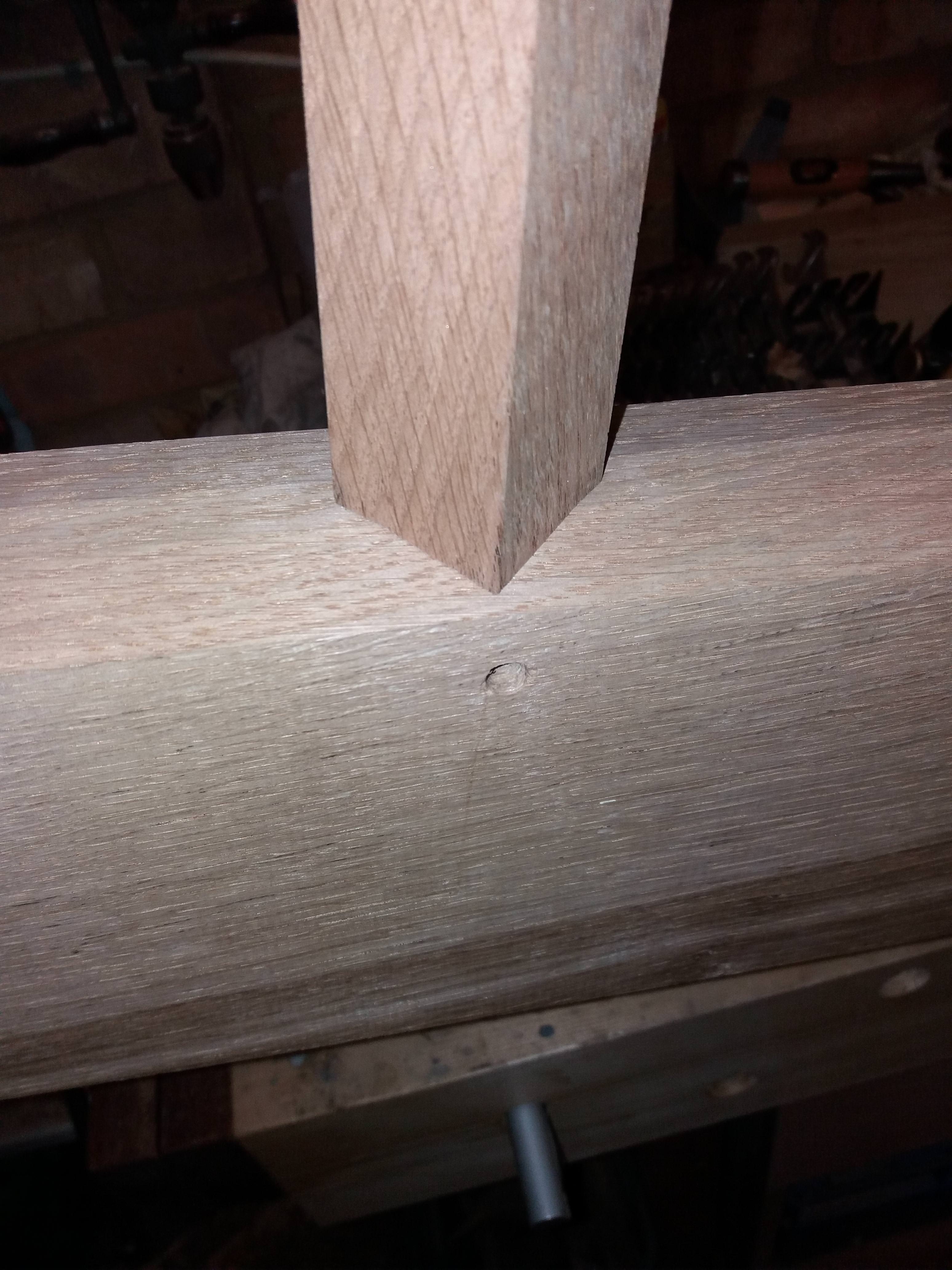
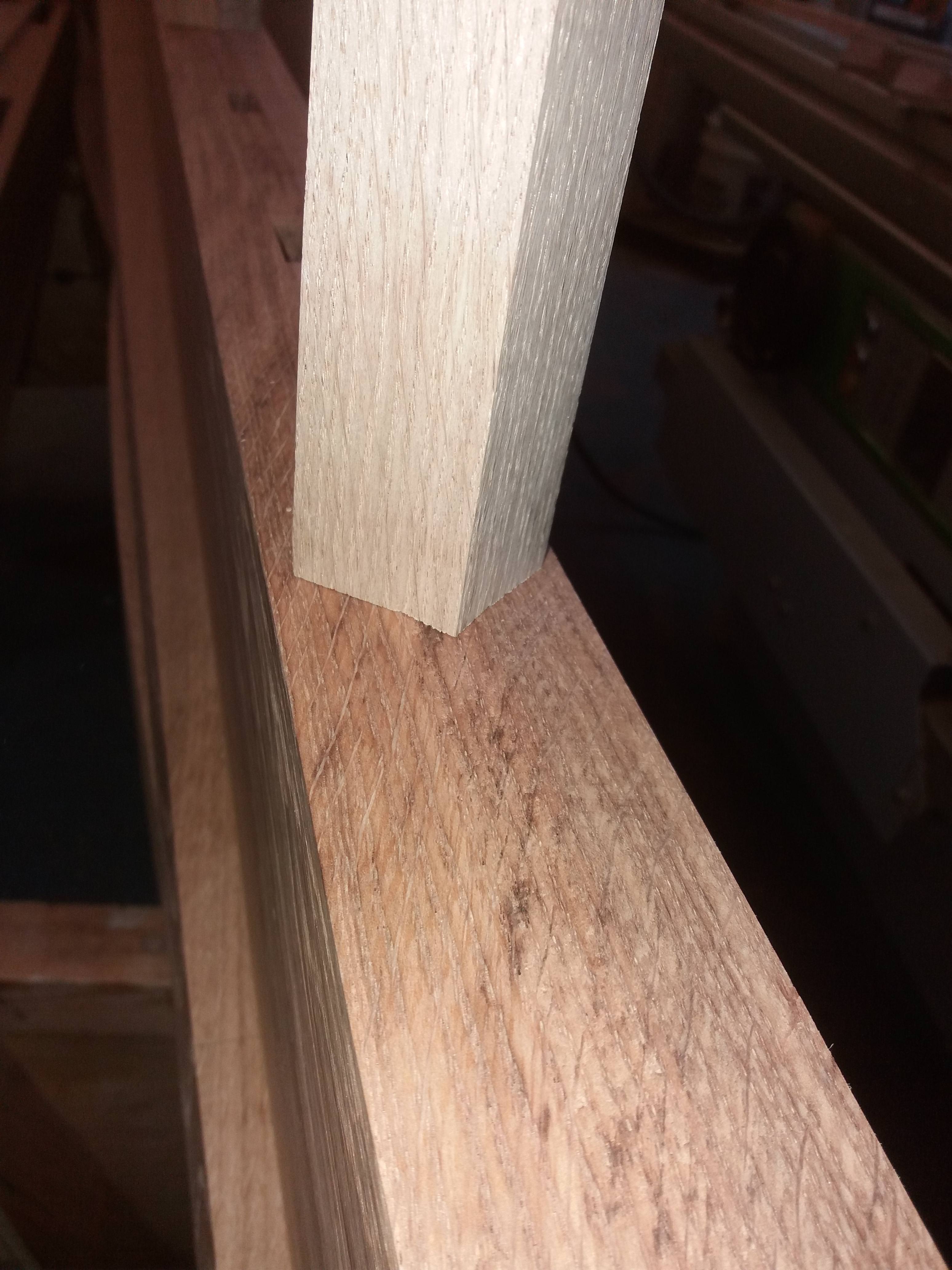
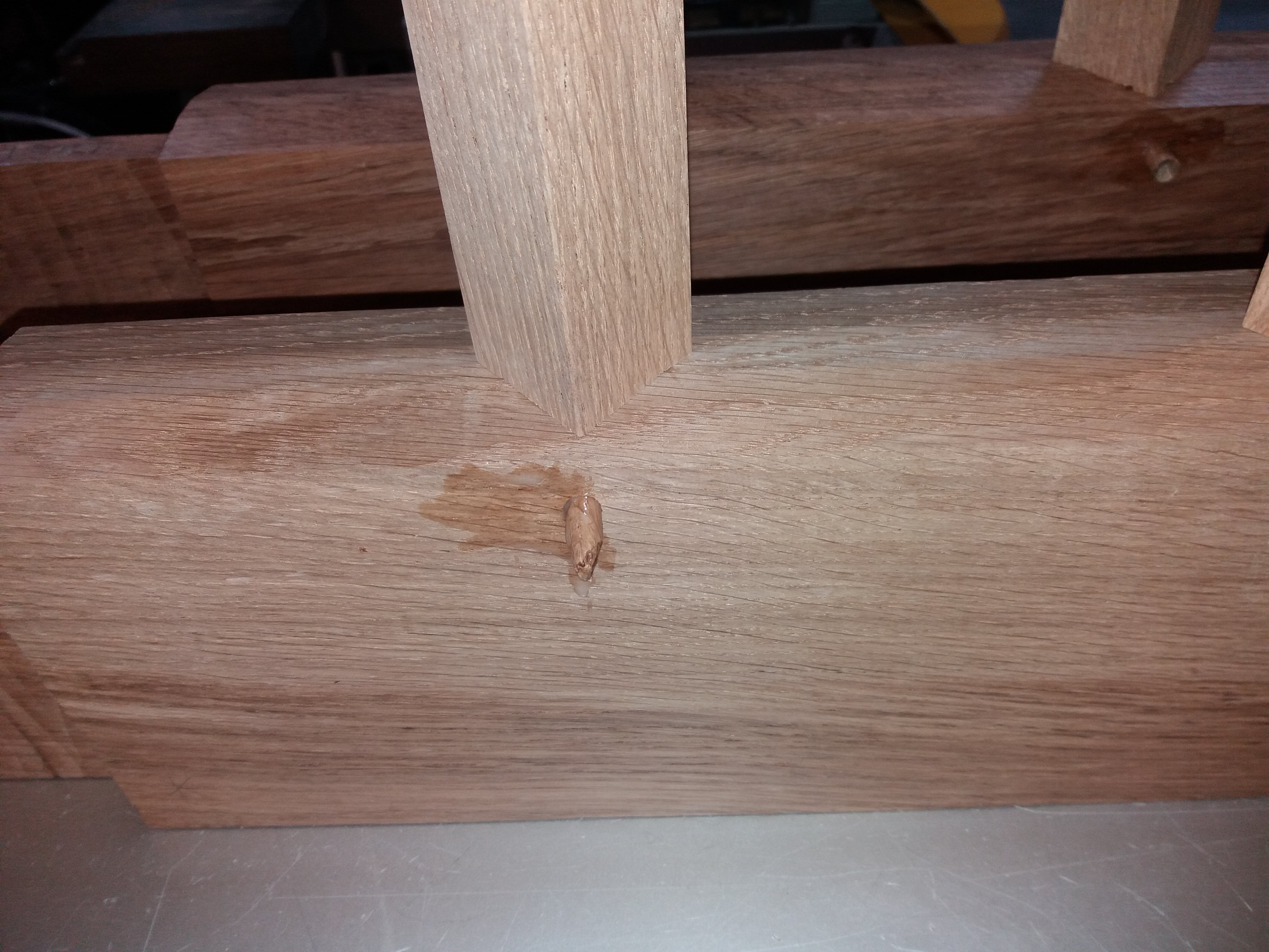
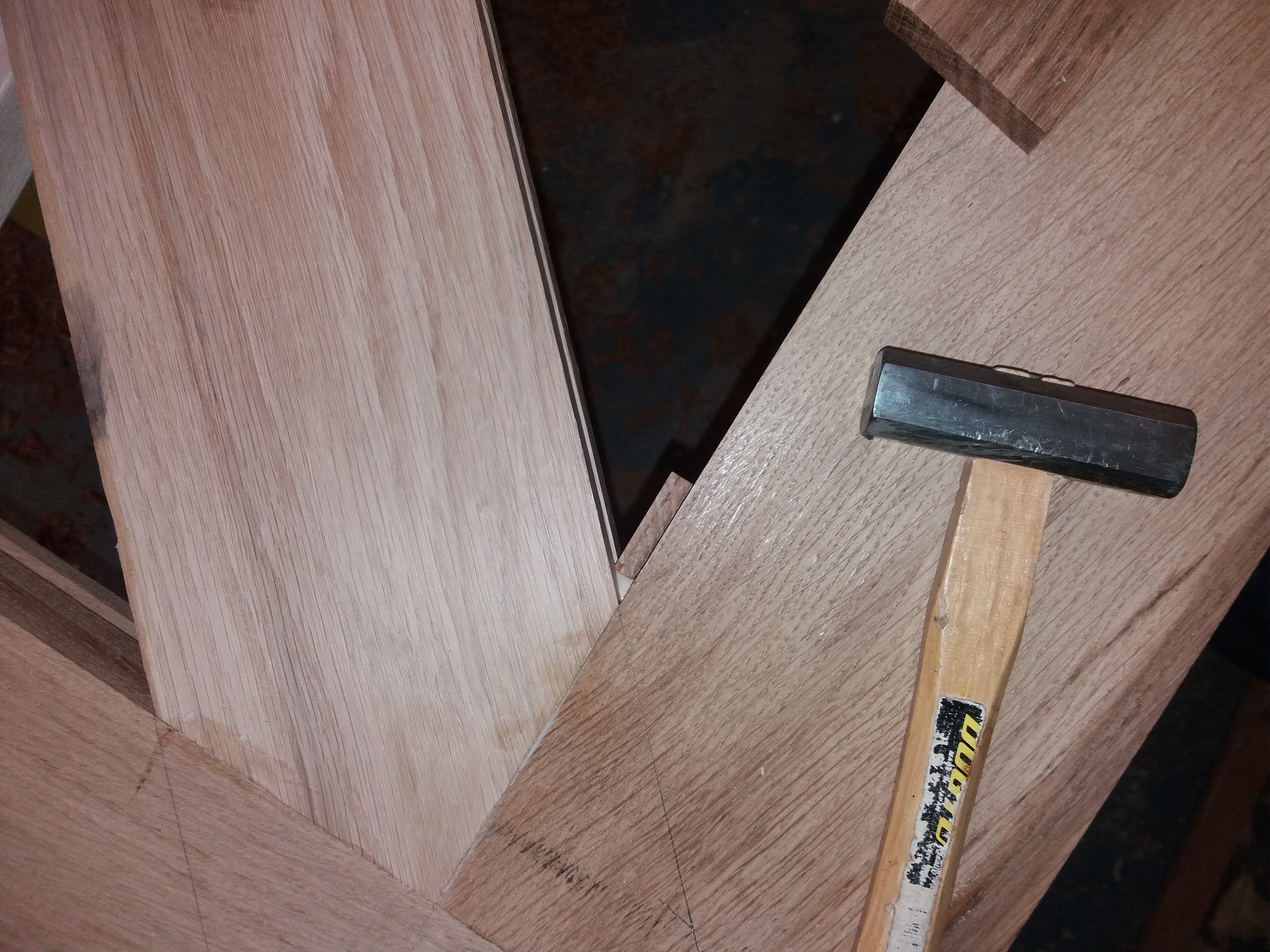
And chopped full size into the underside of the top rail ensuring an interference fit
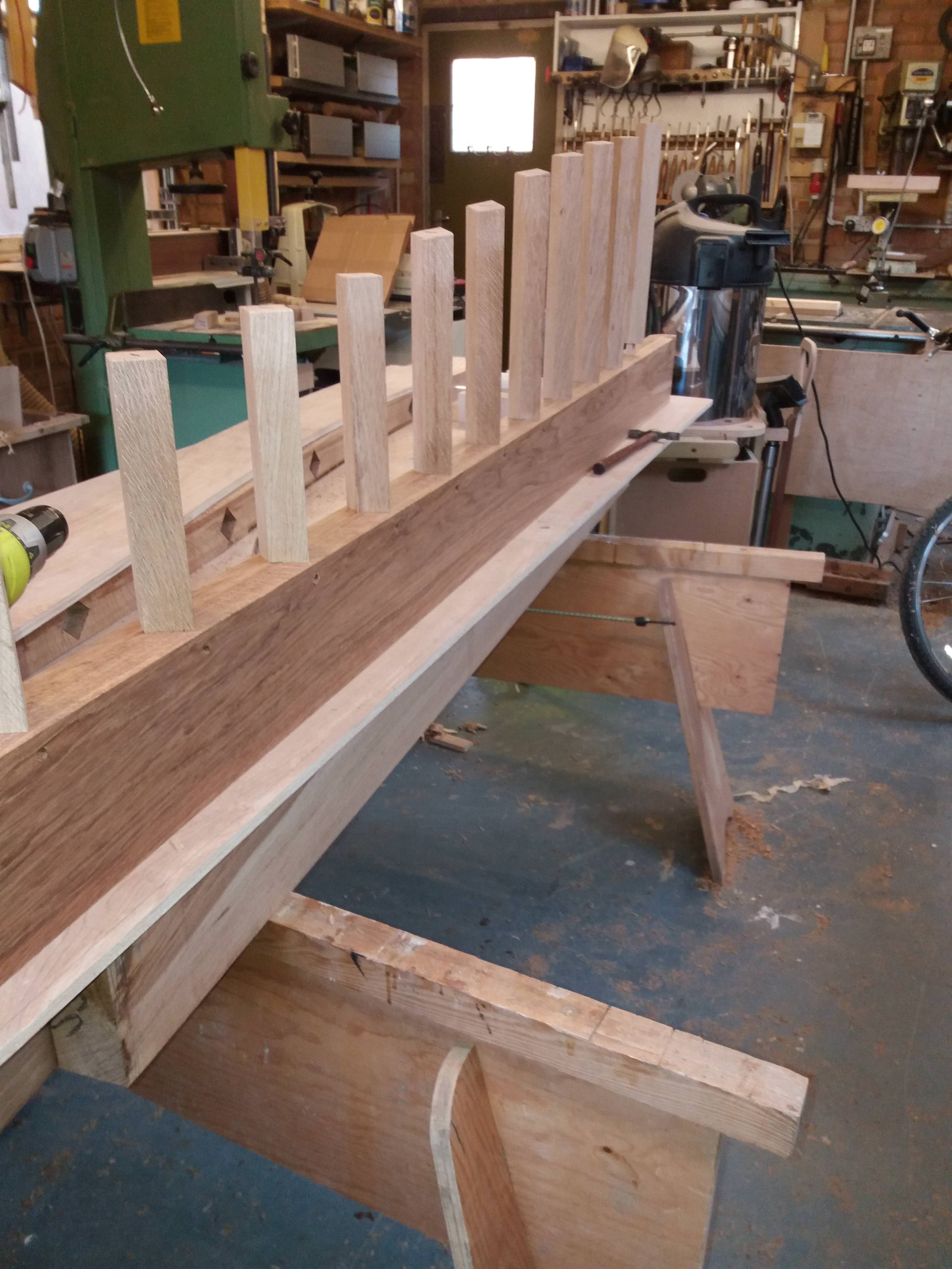
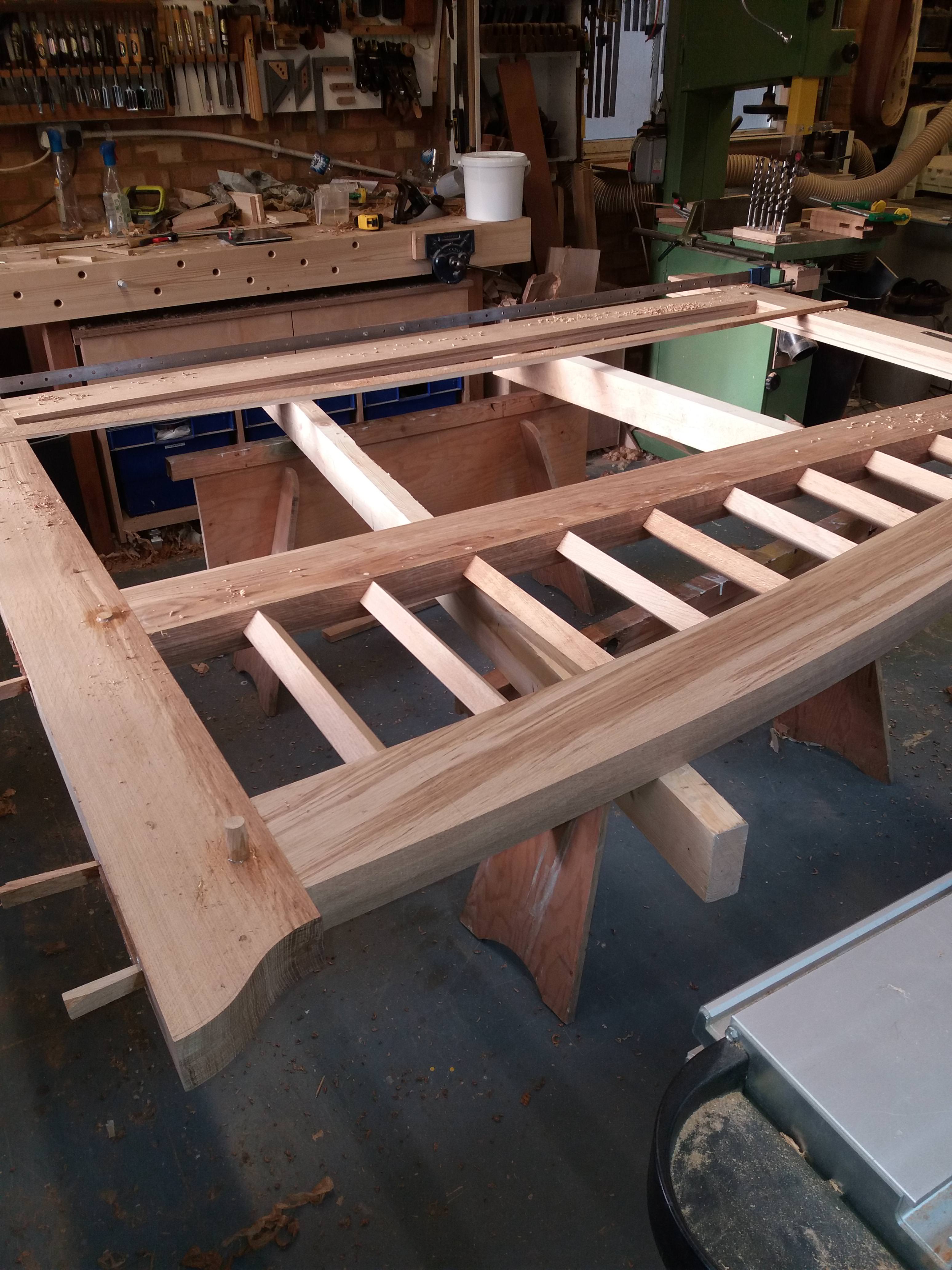
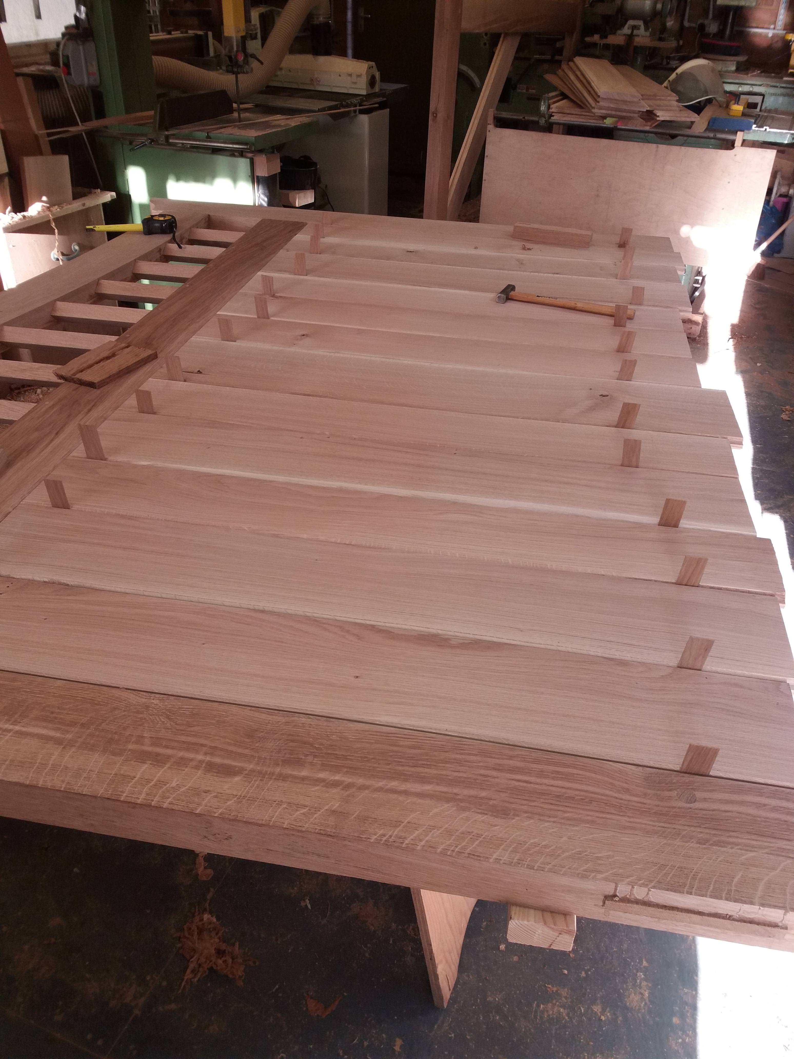
At this stage these timbers were glued and dowelled into the middle rail with the top curved rail located temporarily, squareness was ensured by placing the structure on the setting out rod whilst the glue cured. (cascamite has been used throughout this assembly).
Now the tenons:-
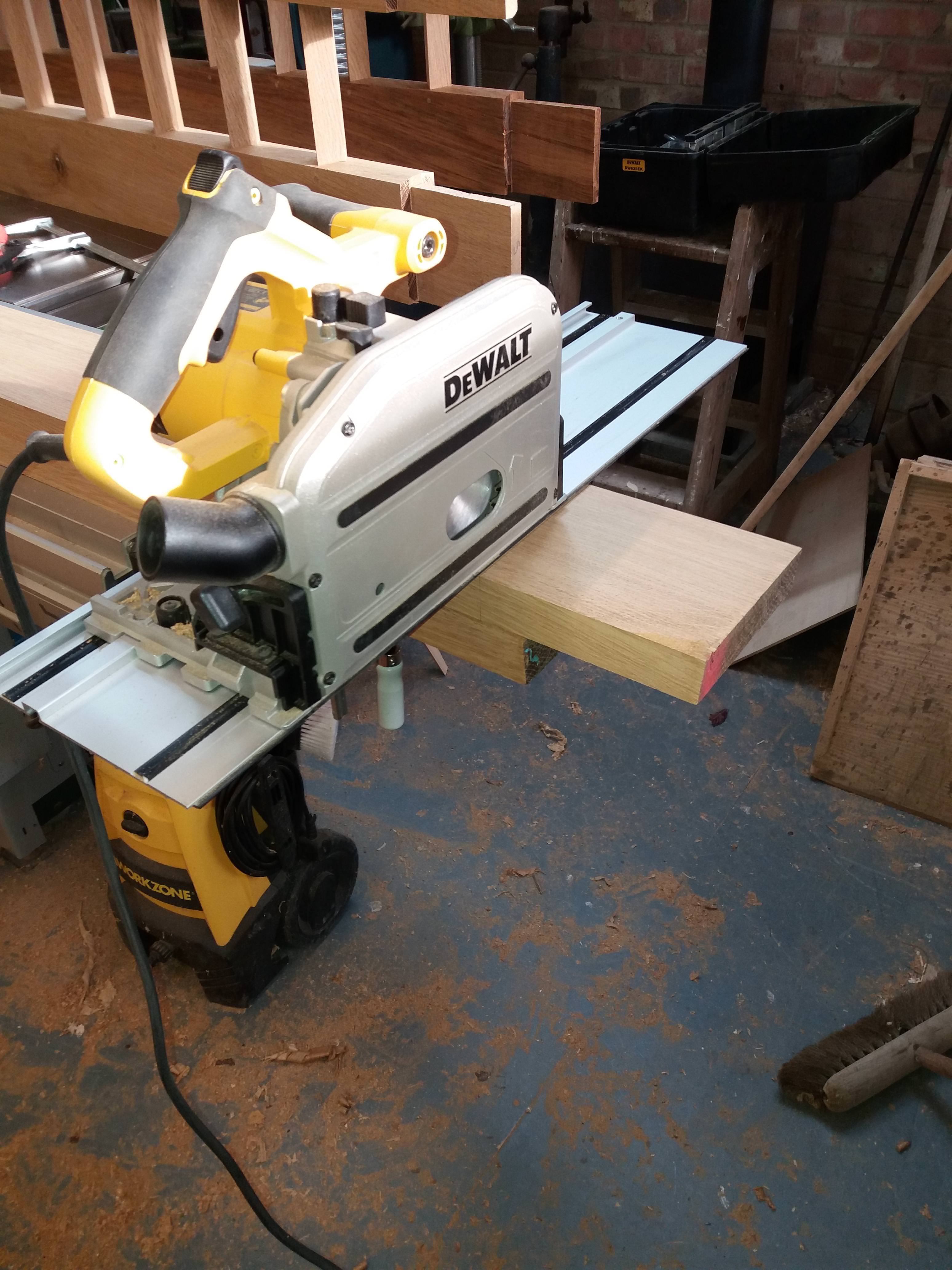
The shoulders were cut out with the track saw
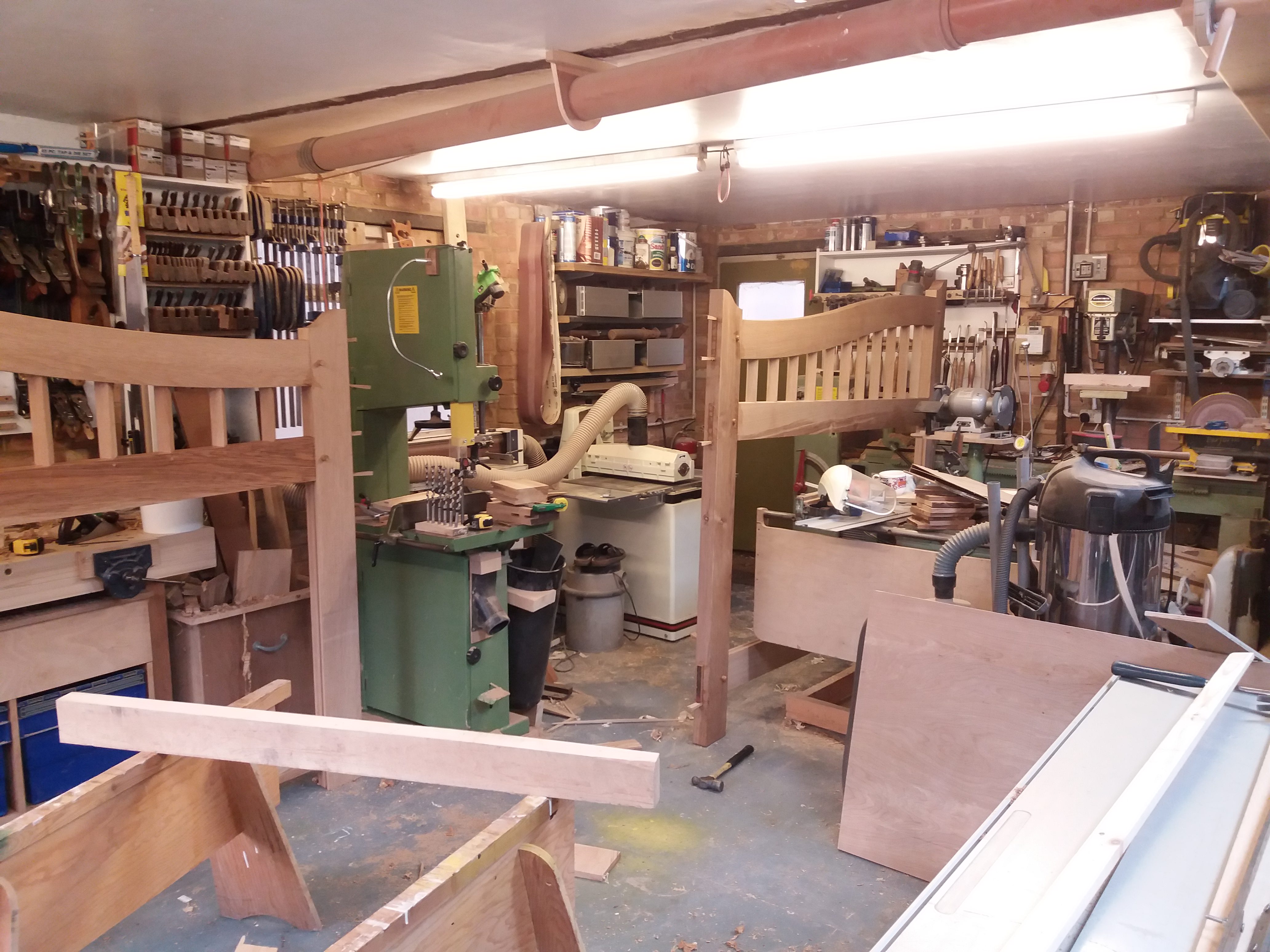
And were roughed out on the bandsaw using the M42 blade
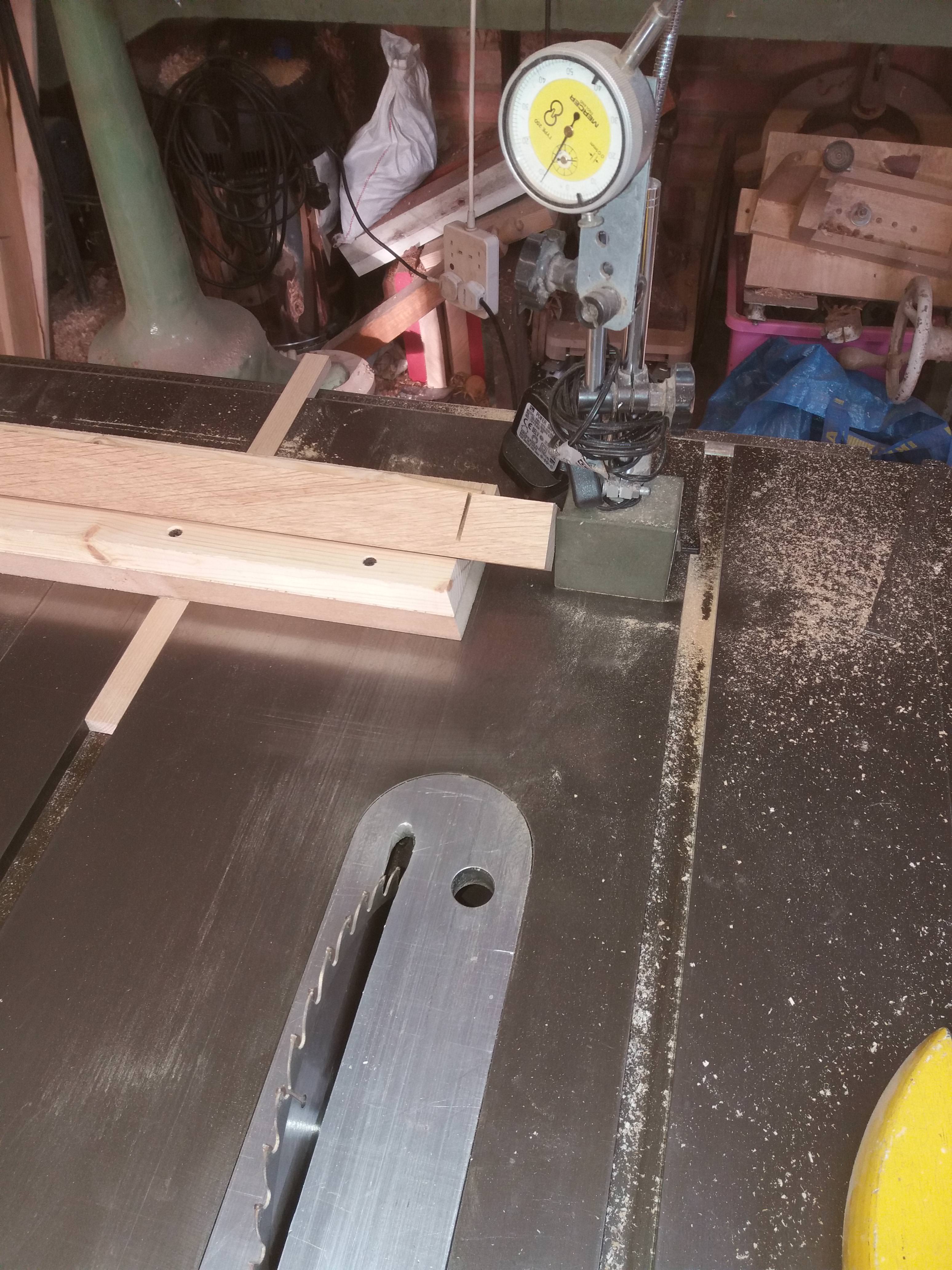
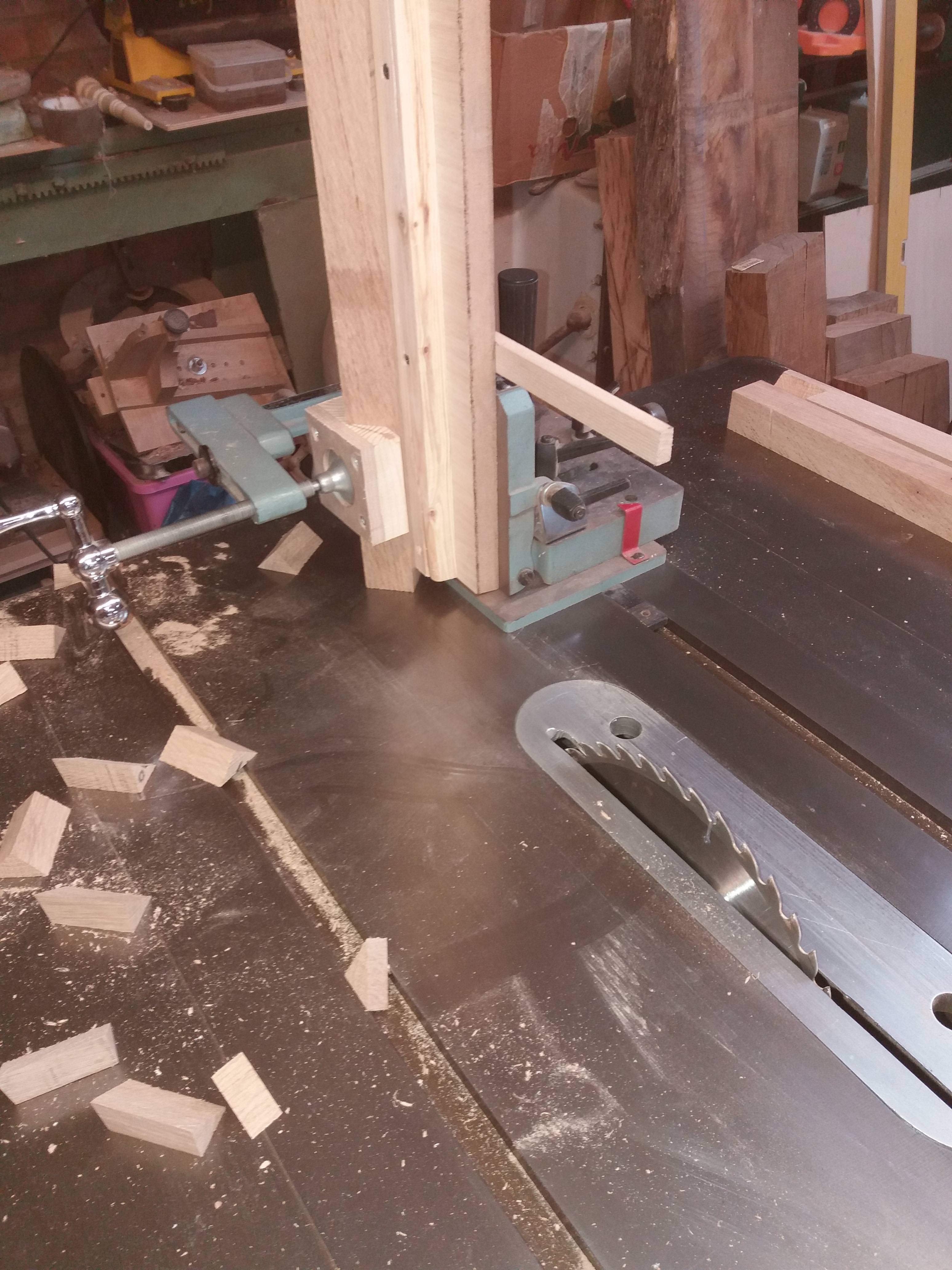
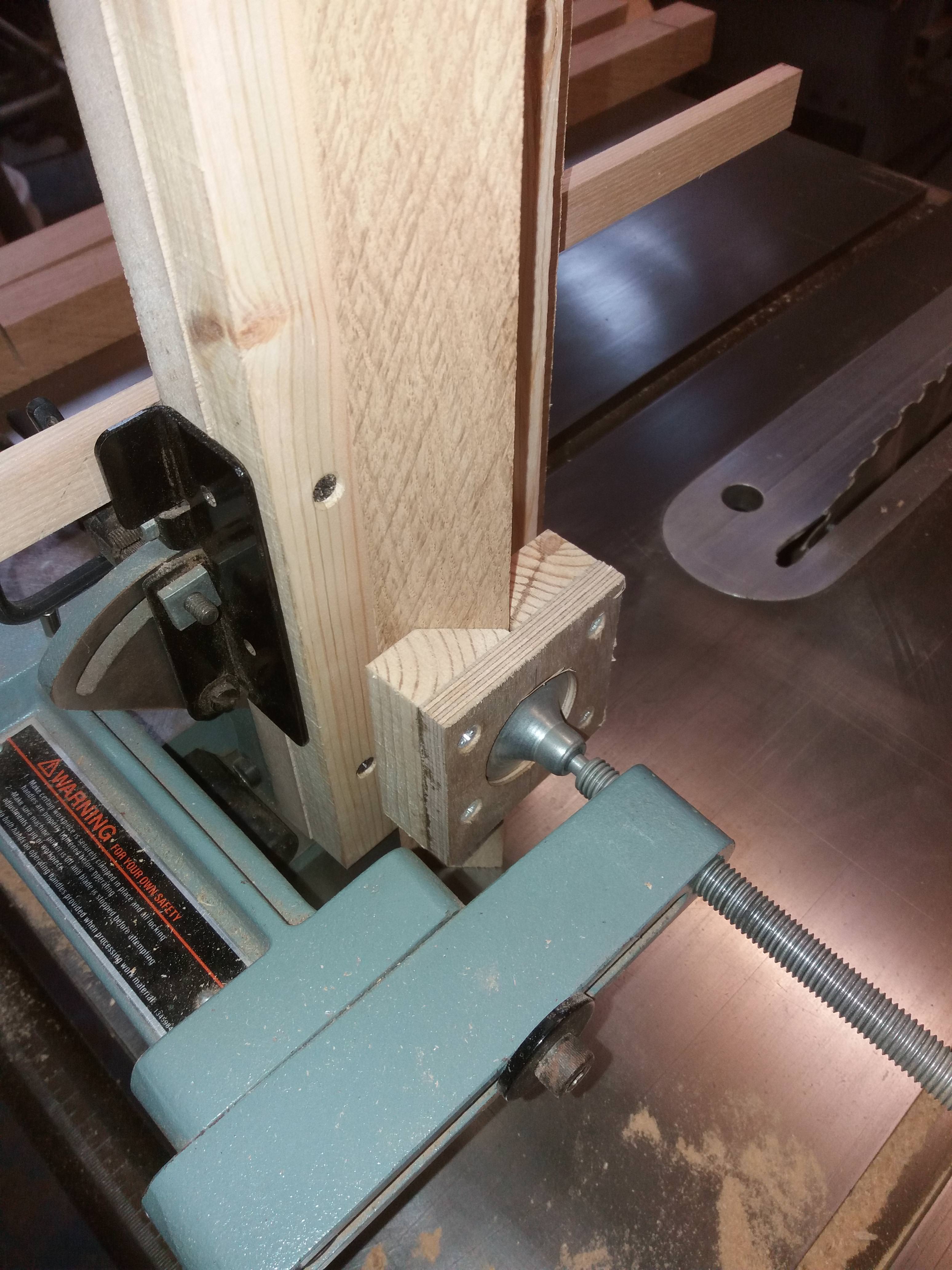
For fine tuning I used a setup with the router
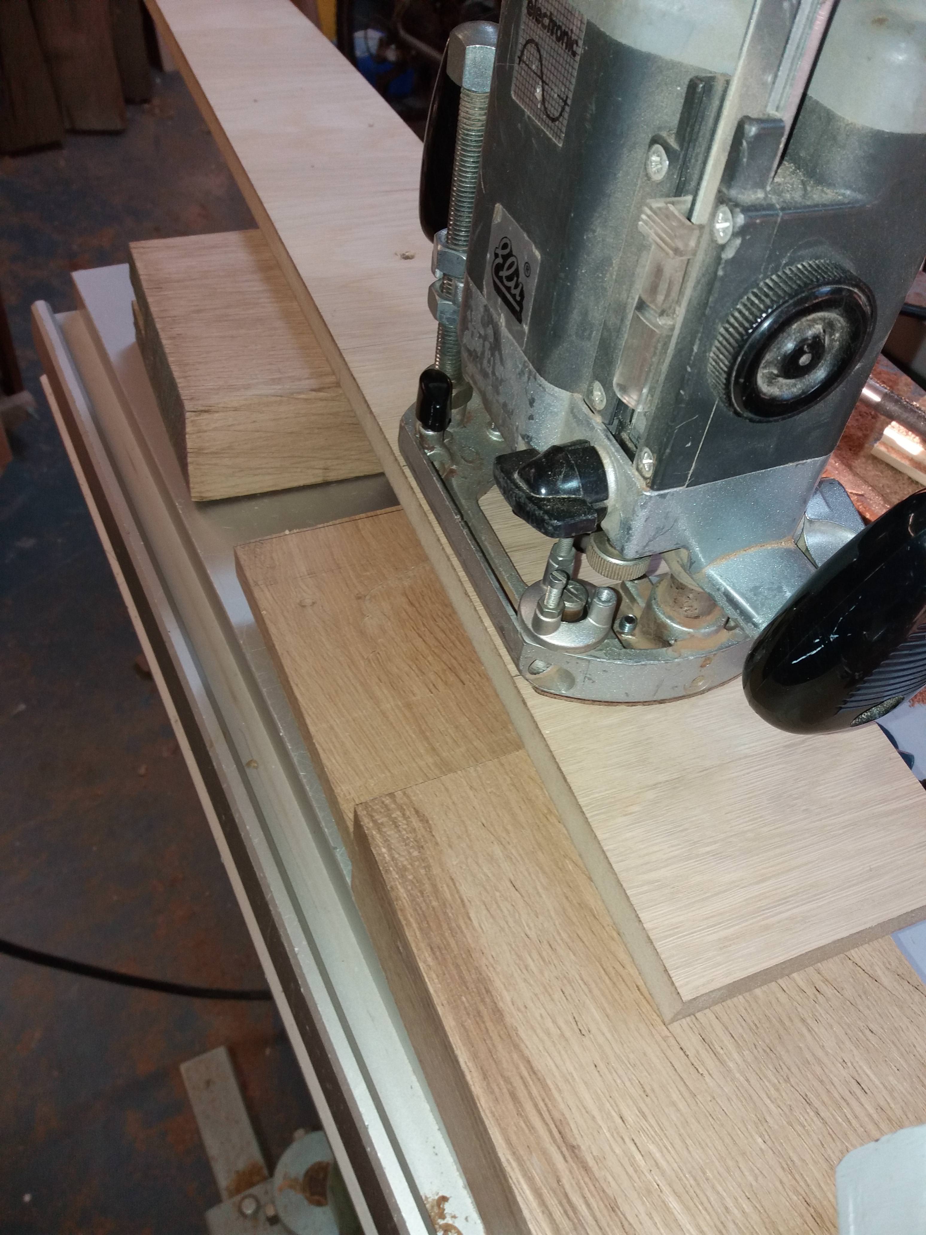
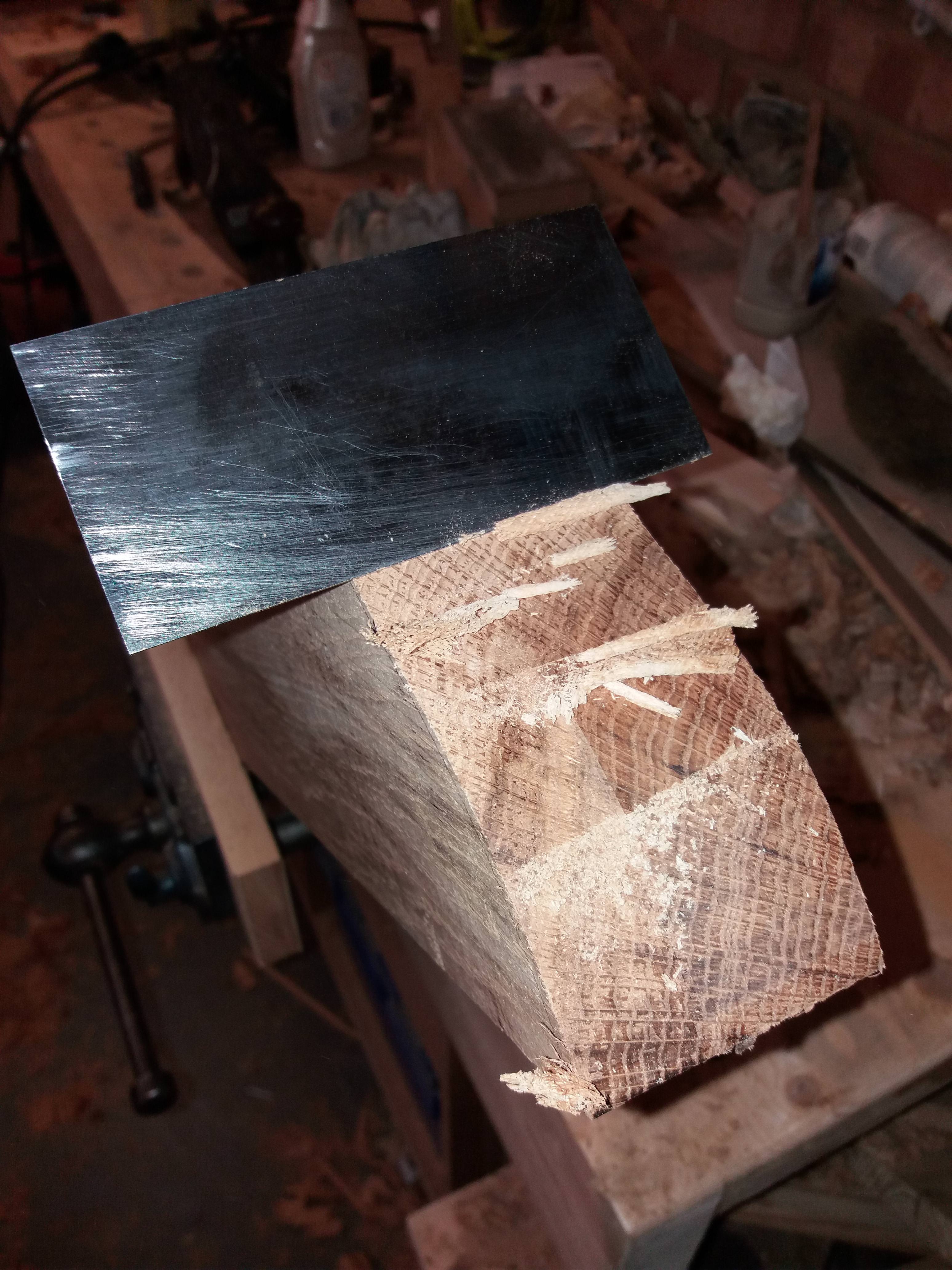
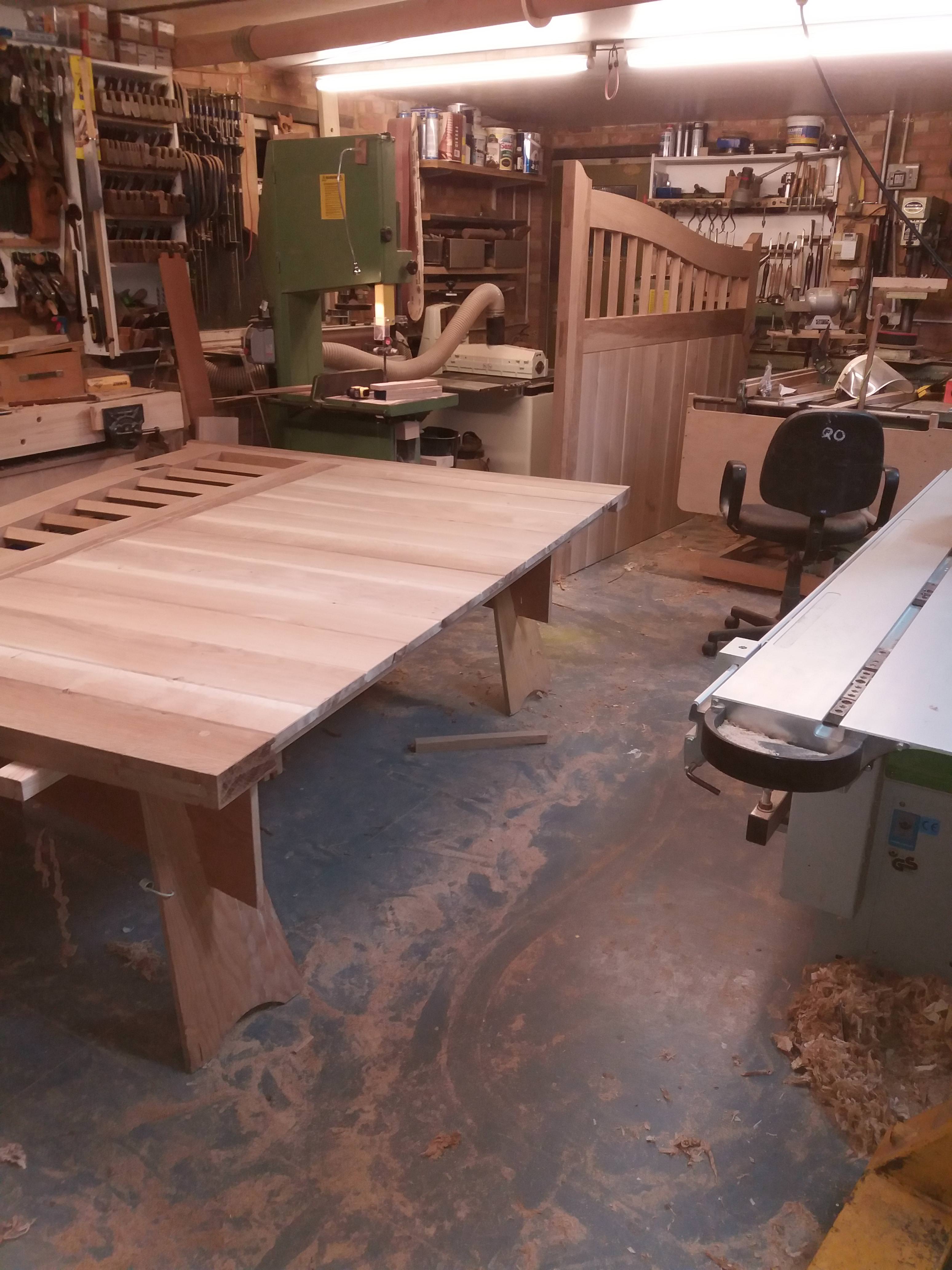
The tops of the stiles were shaped again using the router
And finished with a cabinet scraper
More to follow…
For those interested I’m going to go through the procedures I carried out in making them and identify the problem solving techniques I utilised when using large and heavy materials without assistance.
This is the opening where the gates are destined to go:-
The width of the opening is 4630mm (needed to be this wide so as to facilitate access for my Landrover with the angle of the driveway to the road and the awful steering lock my landrover has).
A sketchup of the intended design is shown here.
Sourcing appropriate material out of air dried oak for this project was proving difficult, eventually I decided on kiln dried French oak and purchased a pack of 80mm (they did 55mm and 80mm, I considered 55mm to be slightly too thin).
The timber as collected:-
It took some effort to get it off the trailer on my own but I eventually managed it
But getting it on machinery alone would prove beyond my reach, therefore with the aid of a chalk line, a straight edge and a 75mm circular saw I managed to get it down to manageable pieces.
The saw wasn’t quite deep enough to cut right through so a recip saw was used for the last 5-10mm
Once down to manageable pieces I was able to cut off the wane on the table saw and get it ready for preparing. The widths of the stiles, middle and bottom rail being 150mm finish and the top curved rail approx 200mm
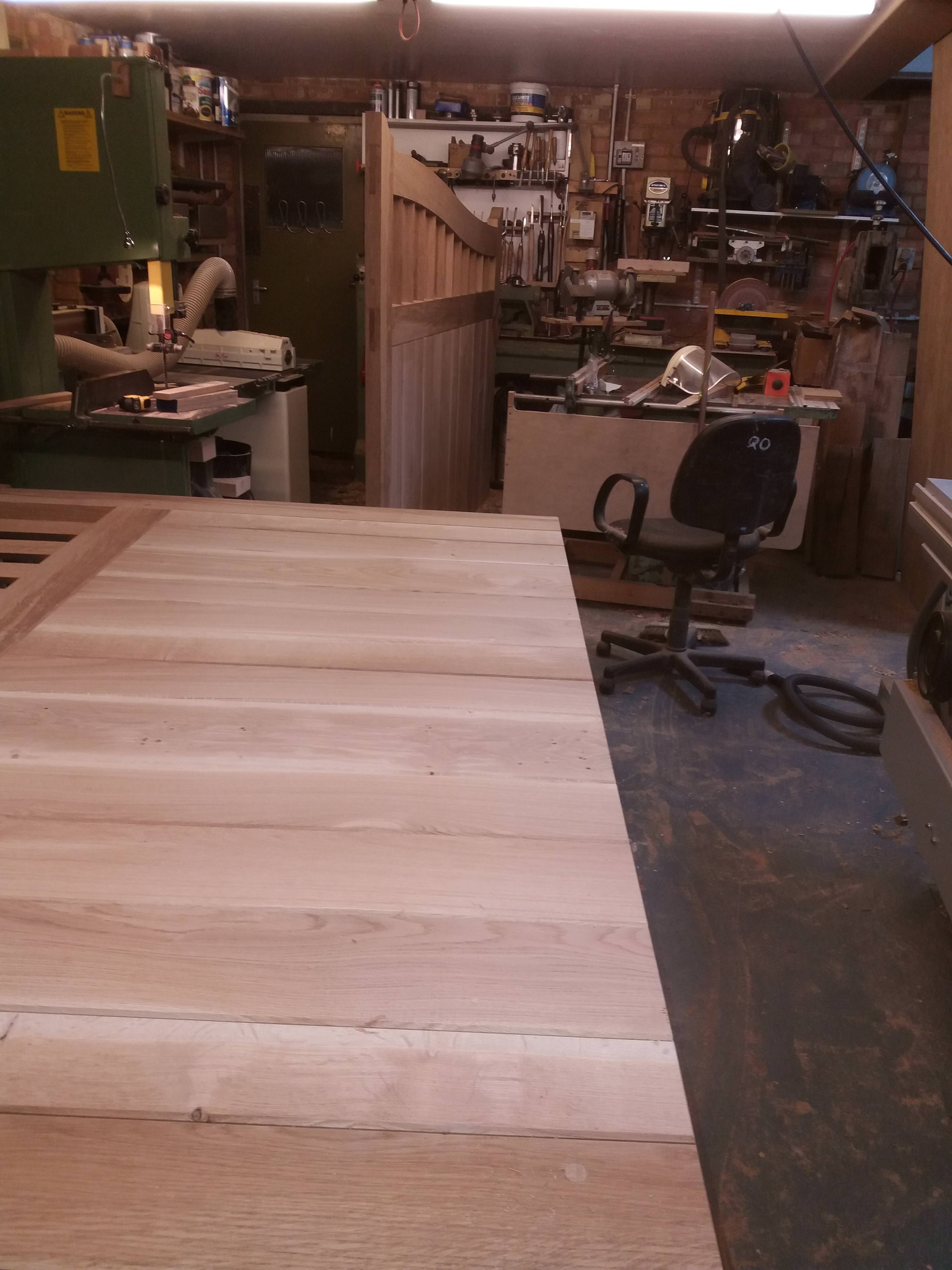
Each gate was going to be approx 2300mm wide and 1850mm at its highest point plus being 80mm+ thick I wasn’t going to be able to surface them flat on my own, so I made this
This has the facility to make it coplanar to the exit table and folds away for storage.
In use
It supported the weight excellently producing a perfectly flat face side.
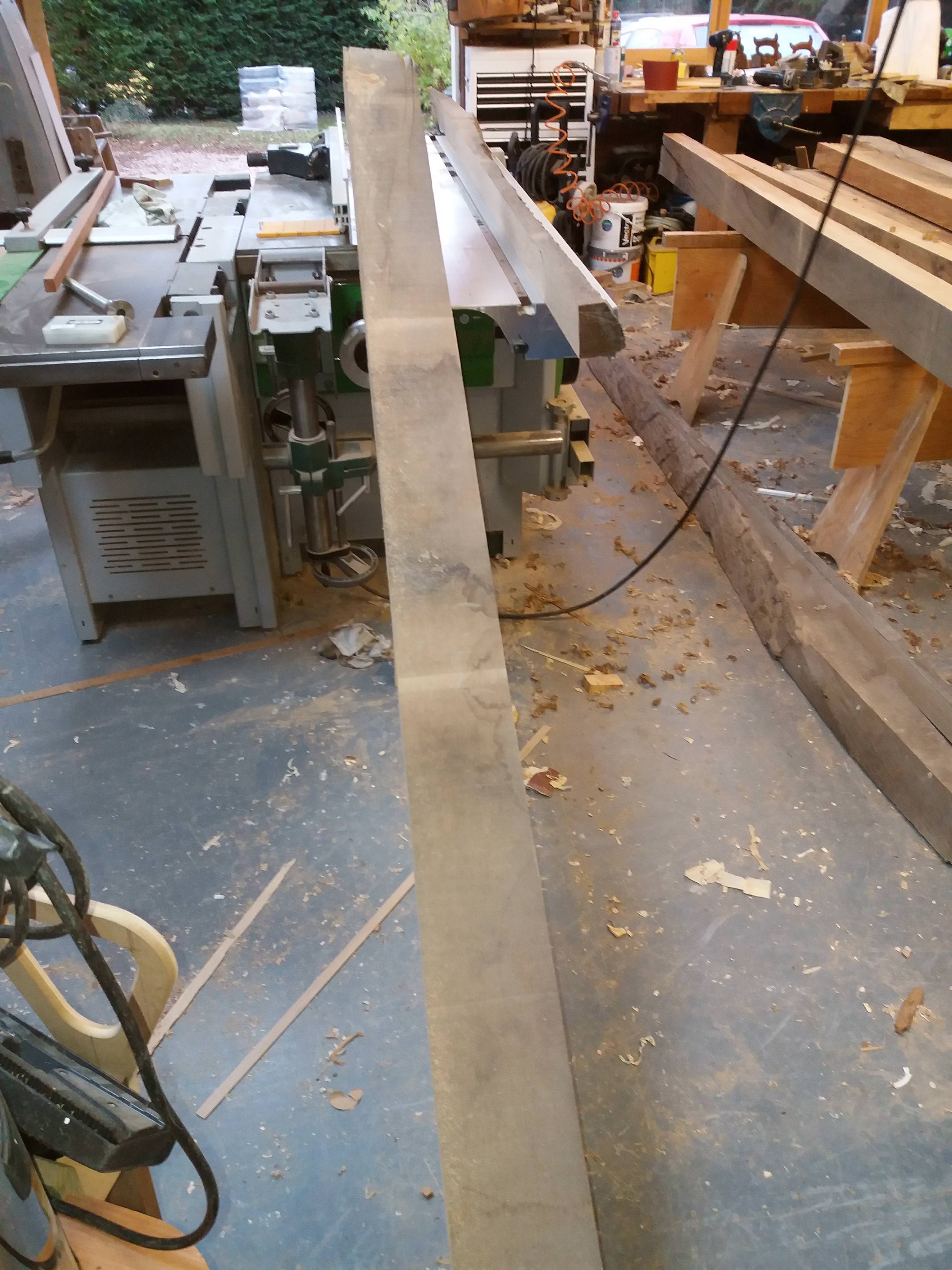
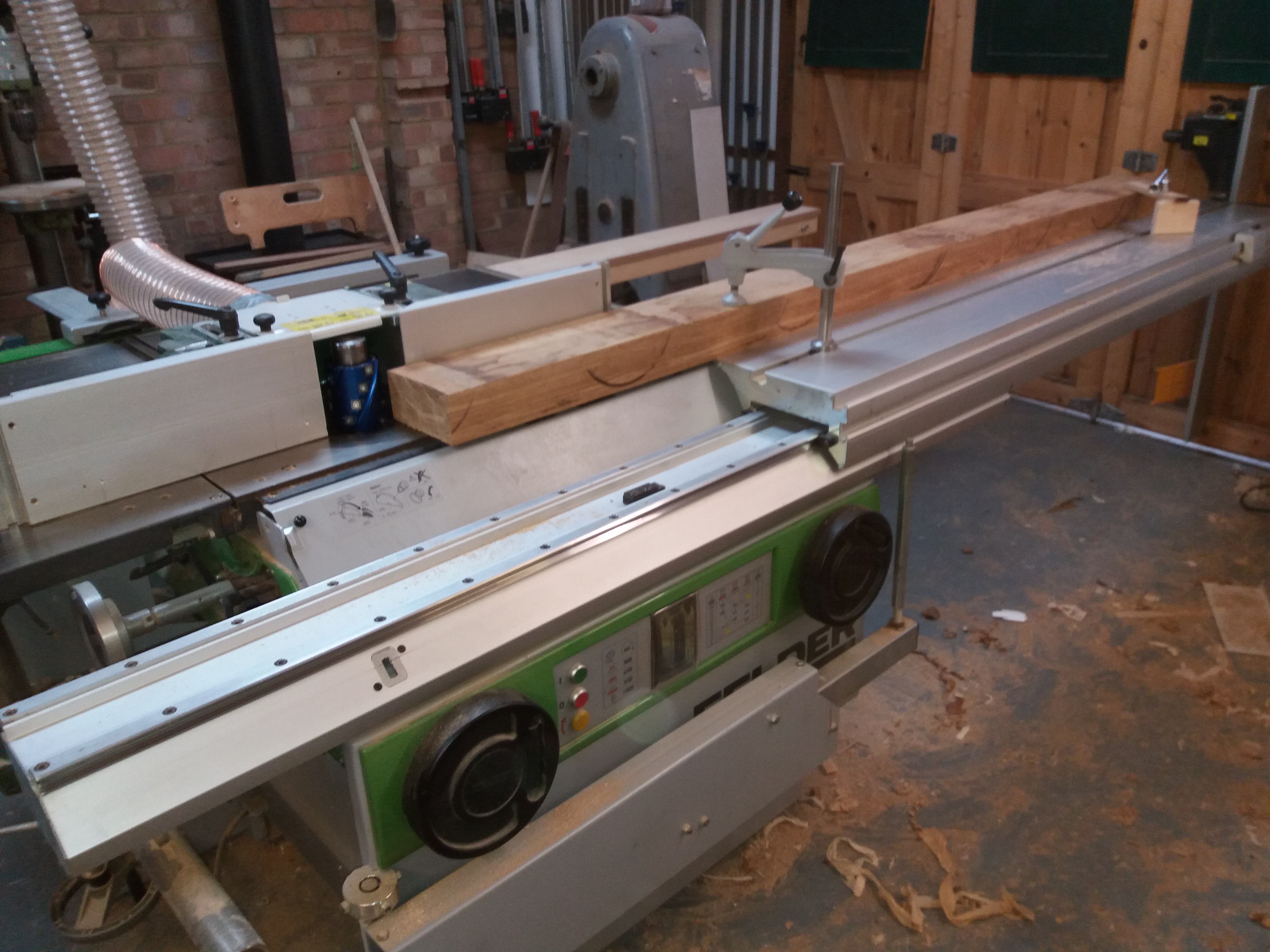
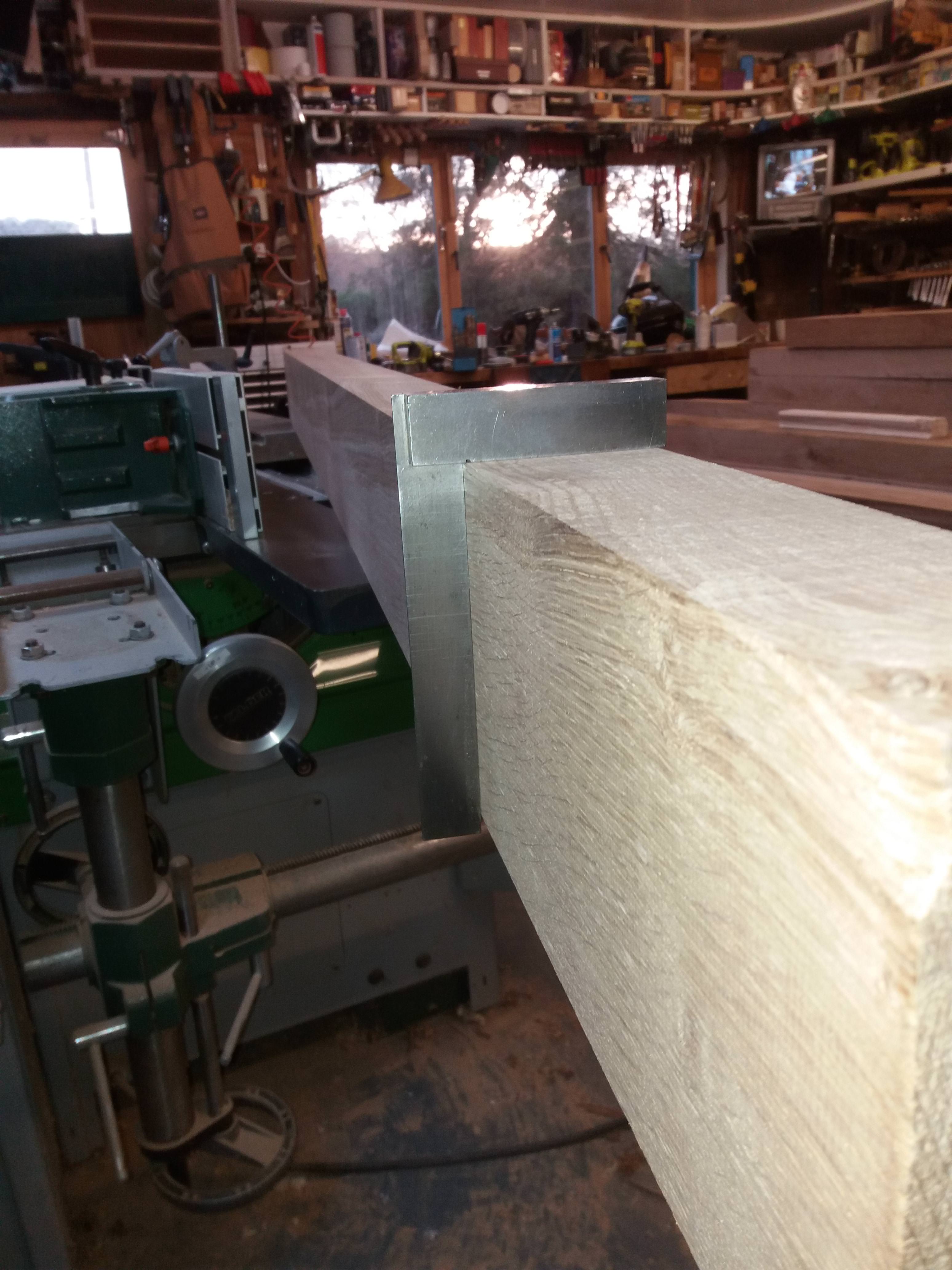
Now the face edge, using the surface planer this would have required me to not only support the timber over the cutter but to also keep it tight up against the fence and with it initially being somewhat out of square I took a different approach. I used the spindle and the sliding table as shown
The timber being clamped down and fed through the cutter. This not only ensured a perfectly square face edge but also a straight one as well.
However for a couple of the pieces the table was not quite long enough with a jack plane being called into service to flatten the last 75mm
As this timber prior to preparing was between 80-85mm thick and my finish size was to be 60mm I didn’t want approx 20mm going up the dust chute as chippings. To solve this I purchased a m42 resaw blade from Ian at tuffsaws which left me with some lovely 15mm+ stock, much of it quarter sawn to use for drawer sides boxes etc.
In addition the bottom rail was to be a barefaced rail to which I could just get two out of one piece of 80mm (it was actually about 87mm). The table support I used on the planer also came into service again.
The rippings
The top half of the gate was set out on a board full size, to set out the curves on the top rail if I were to use trammels I would have needed a radius of approx 5m which was not doable. I considered a bendy lath but considered this not accurate enough. Therefore I employed a process I have used in the past to set out large but shallow bow windows. It’s called a camber slip and exploits the fact that the angle in an arc remains constant (could explain it better but this might help, angle X remains constant as it moves round the arc)
The process as used by myself using a couple of pins in the setting out board
Eventually I was able to produce a full-size template of the top rail
And used it as a template for a router and bearing cutter to shape the top rail.
Everything else was set out from the rod and morticed
Timbers were to be morticed into the top section at a 45 degree angle but prior to this the top edges of the middle and top rail were bevelled to prevent water retention I will hope the photo’s will show how I cut the tenons on the above mentioned timbers.
These were draw dowelled into the middle rail
And chopped full size into the underside of the top rail ensuring an interference fit
At this stage these timbers were glued and dowelled into the middle rail with the top curved rail located temporarily, squareness was ensured by placing the structure on the setting out rod whilst the glue cured. (cascamite has been used throughout this assembly).
Now the tenons:-
The shoulders were cut out with the track saw
And were roughed out on the bandsaw using the M42 blade
For fine tuning I used a setup with the router
The tops of the stiles were shaped again using the router
And finished with a cabinet scraper
More to follow…


")