Modifications to a Startrite bandsaw

UKworkshop.co.uk

Help Support UKworkshop.co.uk:

This site may earn a commission from merchant affiliate links, including eBay, Amazon, and others.

9fingers

Established Member
Joined
26 Jul 2005
Messages
5,000
Reaction score
3
Location
Romsey, Hampshire
A while back I picked up a secondhand Startrite 18-S-1 bandsaw that was in a bit of a sorry state. New bearings and guides have got it running sweetly but it was missing band wheel brushes - normally two are fitted.
Metal dust was starting to get embedded in the tyres and new tyres are very expensive so I need to look after these ones

I've now fitted a brush to the driven bandwheel. I've also made a few other mods which may be of interest.

First the brush bought on ebay here http://cgi.ebay.co.uk/ws/eBayISAPI.dll? ... 0412799232

IMG_0989.jpg


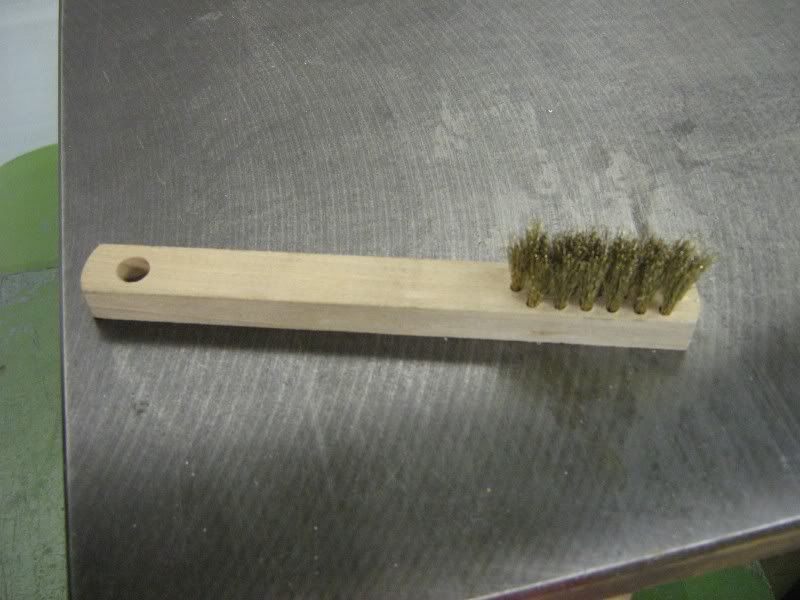
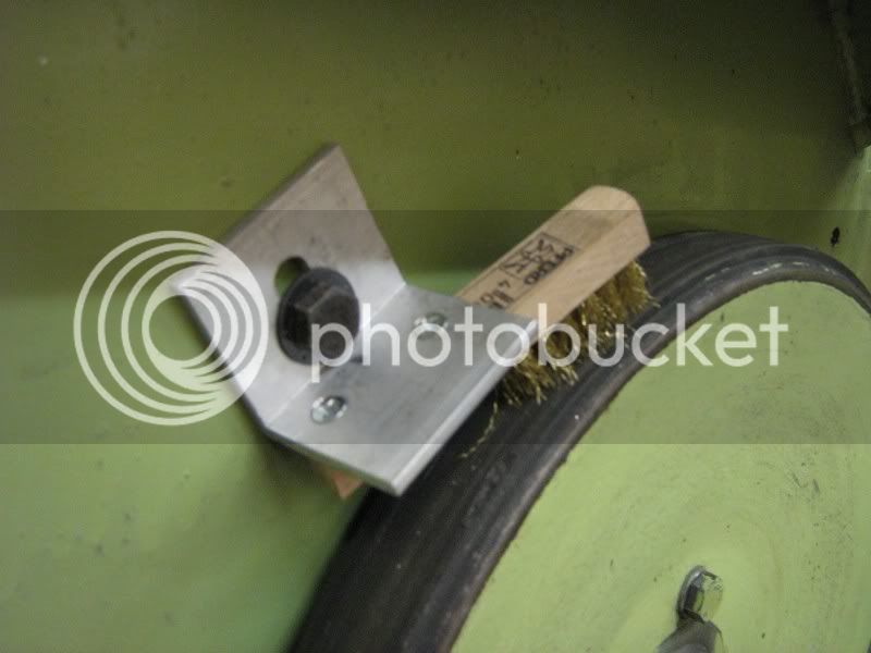
A simple angle bracket with the brush screwed on at an angle sweeps the full width of the tyre. I've only put one on for now and I'll see how it goes. For anyone retro fitting a brush, the thread tapped into the body of the saw is 5/16 Whitworth. If you don't happen to have a suitable bolt then the hole can be drilled out 8.5mm and tapped M10.

IMG_0988.jpg


The "1" in the model number 18-S-1 means it is a single speed machine. Other models are -5 and -10 with that number of speeds.
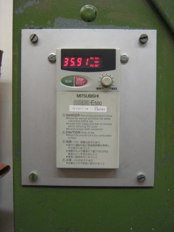
Unmodified, the blade speed is around 3500 feet per minute which is fine for wood but I also work in plastic and metal which needs much lower speeds. My saw is a 3 phase model and I have fitted an inverter which gives me not only operation from a single phase supply but also gives variable speed.
Realistically, an inverter can only give useful power output down to 1/5th of normal speeds although mine is programmed for 1/10th of normal. The inverter is fitted in the space occupied by the NVR switch and performs this function as well.
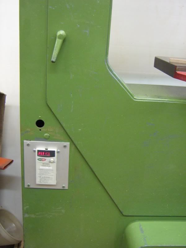
IMG_0991.jpg


and close up

IMG_0990.jpg


The inverter alone really only gives useful minimum speed of 700 feet per minute which is still too fast for metal other than thin soft metals such as aluminium.

The next modification is to fit alternative belt drive.

This is the standard belt drive fitted with the driven V pulley hidden by the new MDF pulley

IMG_0994.jpg


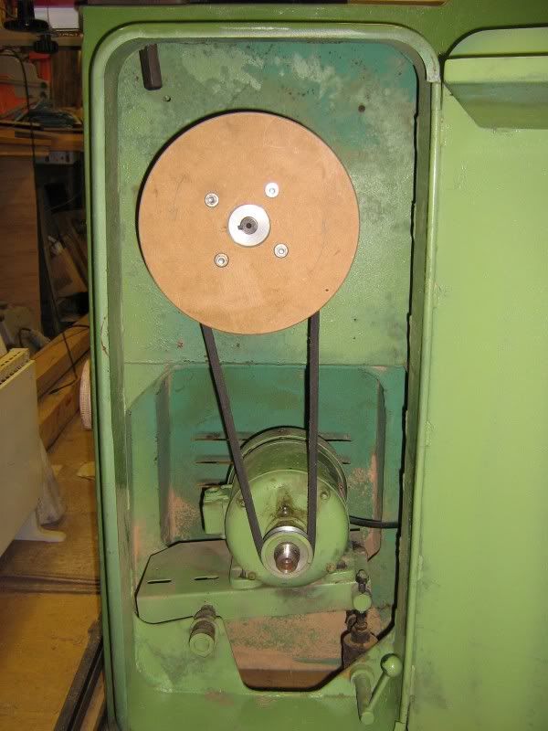
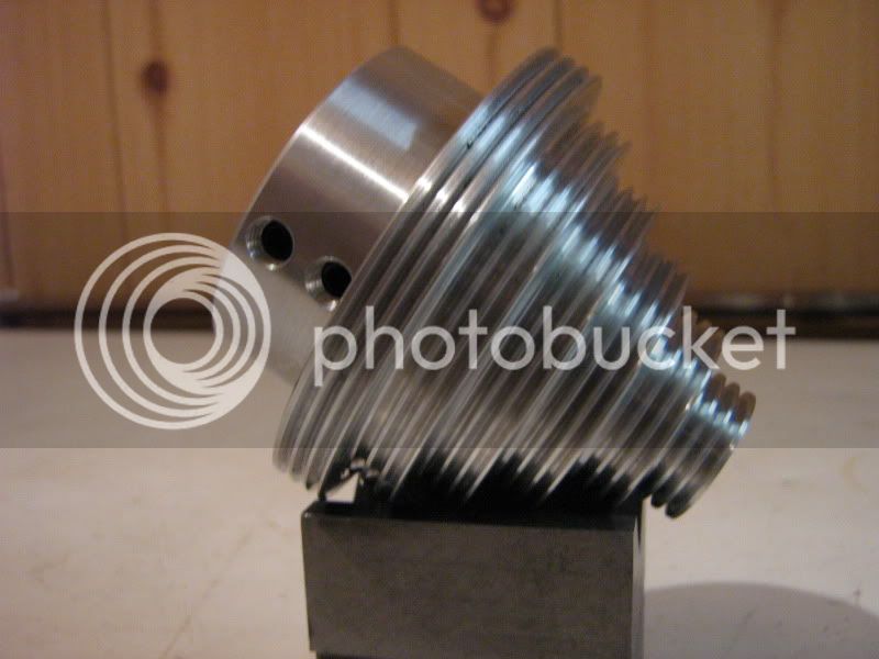
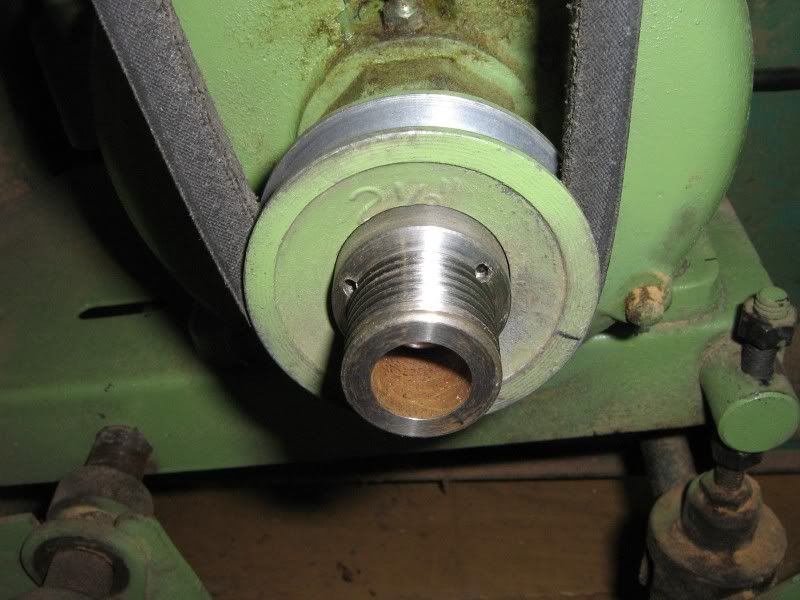
The new low speed belt drive uses a poly V belt - the sort you find in most washing machines. These are much more flexible and so give good grip on small diameter pulleys like the one below.

IMG_0995.jpg


There is no need to cut the multiple Vs on the big pulley - another tip taken from the washing machine design that donated the belt.
Either belt is tensioned by the weight of the motor as per the original Startrite design.

Both new pulleys are bolted onto the existing ones and turned to run concentrically

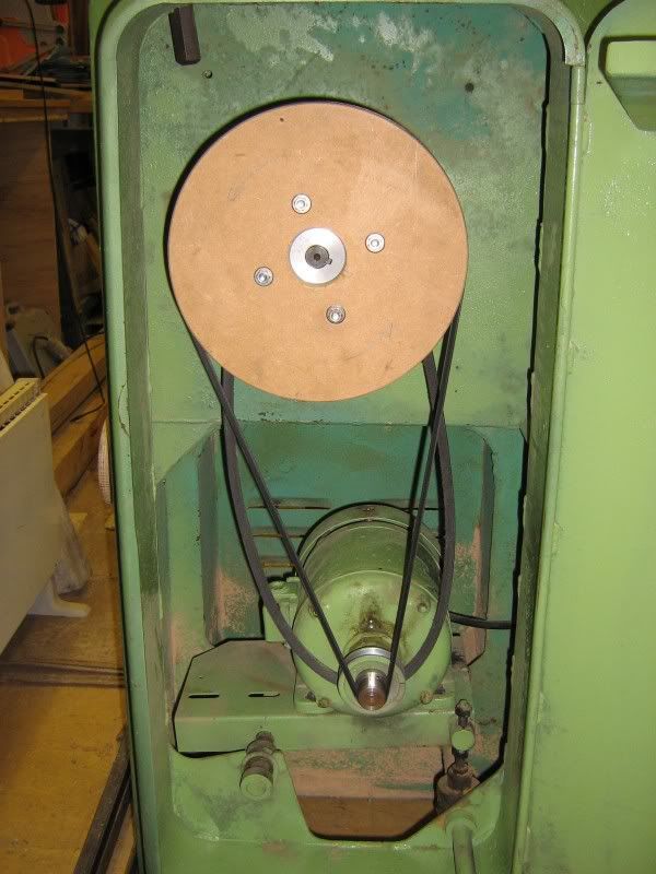
In the low speed mode, the high speed belt hangs off the top bearing housing out of the way

IMG_0996.jpg


The original belt drive gives a ratio of about 2.5 :1 and the low speed drive is about 8.5 :1

The result of combining the belts change and the inverter gives a working range of 100 to 3500 FPM which compares well to the manufacturers 10 speed version that offers 56 to 3200 FPM.

The inverter has a speed control knob fitted which I still use but the stop and start buttons are rather small and fiddly so I have remoted these to an eye level control box here

IMG_0993.jpg


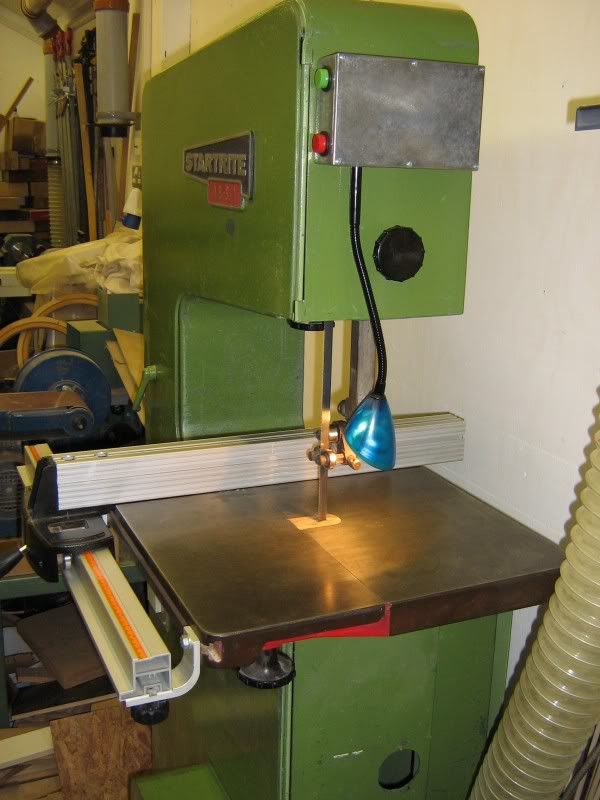
The grey box also has the transformer for the low voltage worklight. All these parts were robbed from a cheapo Argos desk lamp bought for a few quid in the sales. Eventually I will paint over the translucent blue lamp head which is "so last decade" :lol:

The photo also shows the Axminster fence fitted as the original one had been lost by previous owners.

All in the mods cost me about £50 plus the fence which was a present and have transformed the saw into a versatile machine.

Bob
 
Looks like you've put a lot of good work in to this, Bob. I'm sure it will prove to be useful for many, as the years go by. :wink: I like the way you've set the brush so that the whole width is used - on my SIP machine, the tyres have worn away a 'channel' in the bristles where it's been fitted at 90° to the wheel. :x

What is the dust extraction like below the table?
 
Great post Bob, thanks for sharing. I'm undoubtedly going to go for old machines when\if I upgrade my TS & BS. Good to know what can be done.
 
OPJ":lt54hz98 said:
What is the dust extraction like below the table?

The extraction port is rectangular and about 50 x 60 mm. I have made a crude adaptor to my 100mm round pipe system and it needs some aerodynamic fettling as it whistles annoyingly.
Also the rubber seal around the blade access door has perished and I need to arrange a roll of draught stripping that I have 'somewhere' :roll: to fix itself on the door.

The dust is a gravity feed from the blade and the Burgess cyclone takes it away but dust does collect elsewhere and needs persuasion with a hand brush. I changeover blades relatively often to suit different materials so give it a brush out then.

As designed, the machine dumps the dust on the floor via a chute so any extraction is better than that but I'm sure I can fine tune it. - one of the benefits of not having to work for my living is that I can devote time to this sort of fettling. I find it very satisfying use of time.

Bob
 
That is a superb post Bob and a lightbulb just went off in my brain relating to the MDF pulley and the lack of countershaft on my ML1

Can you show me the design of the larger MDF pulley....what a brilliant cheap idea! There was me looking for a large countershaft pulley...and all along I had the stock to build one in the shop!

Very interested indeed!

Jim
 
Nice restoration and mods. I run an S1 at school with an original cast iron fence, that has a broken adjuster, the chrome lever was great, but someone dropped it and broke it. How good is the Axminster fence and was ir an easy fit?
 
jimi43":fpz9uyj6 said:
That is a superb post Bob and a lightbulb just went off in my brain relating to the MDF pulley and the lack of countershaft on my ML1

Can you show me the design of the larger MDF pulley....what a brilliant cheap idea! There was me looking for a large countershaft pulley...and all along I had the stock to build one in the shop!

Very interested indeed!

Jim

The MDF pulley is made from 18mm stock and has a shallow channel about 5mm deep and just over the width of the belt which is a J5 section poly V

This leaves cheeks about 3mm wide to persuade the belt to stay on.

I would not use MDF for a standard V belt as the vees will wear quickly.

I used the existing pulley as the hub, bolted on the rough cut MDF disc and then turned up a dummy shaft in the lathe and kept that in the chuck to ensure concentricity. Mount the composite pulley on the dummy shaft and turn the pulley groove. The result must therefore be concentric with the shaft. Simples!

Bob
 
Mike Wingate":1bic8tnc said:
Nice restoration and mods. I run an S1 at school with an original cast iron fence, that has a broken adjuster, the chrome lever was great, but someone dropped it and broke it. How good is the Axminster fence and was ir an easy fit?

The axi fence is fine. I would have designed the clamp handle differently so it did not stick out in use but it grips well. I won't stand much dropping but it does have nice ball bearing slides.

The brackets need about a 2mm register machining on them and a couple of tee nuts making for the slot in the table edge. The fence then sits a gnats cock higher than the table.


PM me for photos etc if you need them.
I'm sure you will have the necessary machinery at school to do this otherwise let me know if you need help munching metal.


Bob
 
I understand that fully now Bob (it took two or three re-reads but I got there).

Question...does the J5 poly belt work on the standard V belt motor pulley or is that modified too?

In other words if I get a small pulley as a hub and do what you say and also use a J5 belt can I use the standard V belt small pulley on the existing motor?

I am nearly done with the countershaft spindle and bearings and mounts...and I have a suitable small pulley for the motor...this would sort out my ratio selection for what I want to do on the Myford.

Cheers mate

Jim
 
jimi43":2jg35eew said:
I understand that fully now Bob (it took two or three re-reads but I got there).

Question...does the J5 poly belt work on the standard V belt motor pulley or is that modified too?

In other words if I get a small pulley as a hub and do what you say and also use a J5 belt can I use the standard V belt small pulley on the existing motor?

I am nearly done with the countershaft spindle and bearings and mounts...and I have a suitable small pulley for the motor...this would sort out my ratio selection for what I want to do on the Myford.

Cheers mate

Jim

The small pulley must be made to the J5 spec. If you look carefully at my photo, you will see this extra pulley profile on the motor shaft.

The spec is available online. I can't remember the pitch off the top of my head but the angle is 40 degrees. I'll look it up and post a link in a bit.

The J specifies the vee dimensions and pitch and the 5 is simply the number of them - some belts are J6 for example.

Here is J3 one I made a couple of months back for a conversion job on a Jet lathe.
The smallest step was 21mm diameter.

IMG_0942.jpg


Bob
 
AH!!! I get it now....sorry for the ignorance!

But I am on a roll now...I think washing machines in the area need to look out this next two weeks I am on leave.

Jim
 
jimi43":13nd1l03 said:
AH!!! I get it now....sorry for the ignorance!

But I am on a roll now...I think washing machines in the area need to look out this next two weeks I am on leave.

Jim

Washing machines might provide you a belt but the small pulley is normally machined into the motor shaft or unhelpfully shrunk on sealed with a dollop of weld.

Bob
 
9fingers":3lqx9fea said:
jimi43":3lqx9fea said:
AH!!! I get it now....sorry for the ignorance!

But I am on a roll now...I think washing machines in the area need to look out this next two weeks I am on leave.

Jim

Washing machines might provide you a belt but the small pulley is normally machined into the motor shaft or unhelpfully shrunk on sealed with a dollop of weld.

Bob

Darn! Ok...starting to think again!

Cheers for the advice!

Jim
 
Poly vee specs here:-

www.naismith.com.au/pdf/poly_v_v_pulley.pdf

Vee dimensions are given in the belt section.

When designing your pulley it is vital that the crests on the belt do not bottom in the pulley grooves AND the crests on the pulley do not bottom in the valleys on the belt.

The is just the same criticality of a standard vee belts but on more surfaces.

This will be a good turning and tool grinding exercise for you!

Bob
 
Thanks Bob...I might just test the old Taylor yet!

It's always the way isn't it...the bit you are trying to make is used on the machine that you would have made it on if it were not to be part of that machine to make it work!!!

:D :D :D

I will overcome never fear!

Cheers again mate

Jim
 
jimi43":nyvjskpi said:
Thanks Bob...I might just test the old Taylor yet!

It's always the way isn't it...the bit you are trying to make is used on the machine that you would have made it on if it were not to be part of that machine to make it work!!!

:D :D :D

I will overcome never fear!

Cheers again mate

Jim

Make a barrelled flat belt pulley first and use this with your J belt running on its back (vees outside). That will drive your lathe enough to use it to make your first proper J pulley.
- ideas born from starting with nothing and building up a collection of capabilities!
Bob
 
9fingers":zd8czsbv said:
jimi43":zd8czsbv said:
Thanks Bob...I might just test the old Taylor yet!

It's always the way isn't it...the bit you are trying to make is used on the machine that you would have made it on if it were not to be part of that machine to make it work!!!

:D :D :D

I will overcome never fear!

Cheers again mate

Jim

Make a barrelled flat belt pulley first and use this with your J belt running on its back (vees outside). That will drive your lathe enough to use it to make your first proper J pulley.
- ideas born from starting with nothing and building up a collection of capabilities!
Bob

Brilliant Watson!

Ok...will take pictures this time....

Jim
 
Bob
Re. the aAxminster fence - I looked recently and they don't seem to stock it now.

Having said that I wrote a letter of complaint to Axminster about this fence (which was never replied to !) as the construction of the clamping roller mechanism is quite unadjustable and its efficacy relies purely on the accuracy of the mechanical build.

I have mine on a TS and I couldn't understand why I was having accuracy problems until one day I noticed the fence sliding sideways. The clamping roller system had drifted such that there was inadequate clamping force - and it wasn't so much a mechanical deterioration but inadequate tolerance allowance in the design. The irony is that a single layer of paper over the roller is all that is now required to generate clamping force.

Rob
 
Nice Work Bob.

I like the fence especially, as that's always been a bone of the proverbial to me, with my 351.

So it's hey-ho to Axminster, and while I am at it, I'll find out if their bandsaw bearing-guides will fit my saw!

Cheers Bob and thanks for an interesting post.
Well done that man!

John :D
 
Back
Top