Dining Room Carver Chairs

UKworkshop.co.uk

Help Support UKworkshop.co.uk:

This site may earn a commission from merchant affiliate links, including eBay, Amazon, and others.

Derek Cohen (Perth Oz)

Established Member
Joined
2 Mar 2005
Messages
3,278
Reaction score
1,528
Location
Perth, Australia
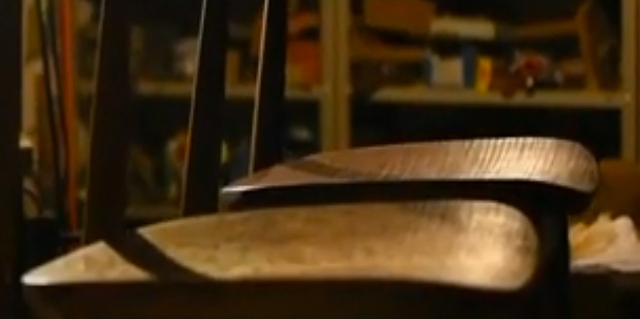
The design of the chair needs to compliment the bentwood chairs we have, which are original and early 1900s. The table is to be replaced with a longer, wider one.


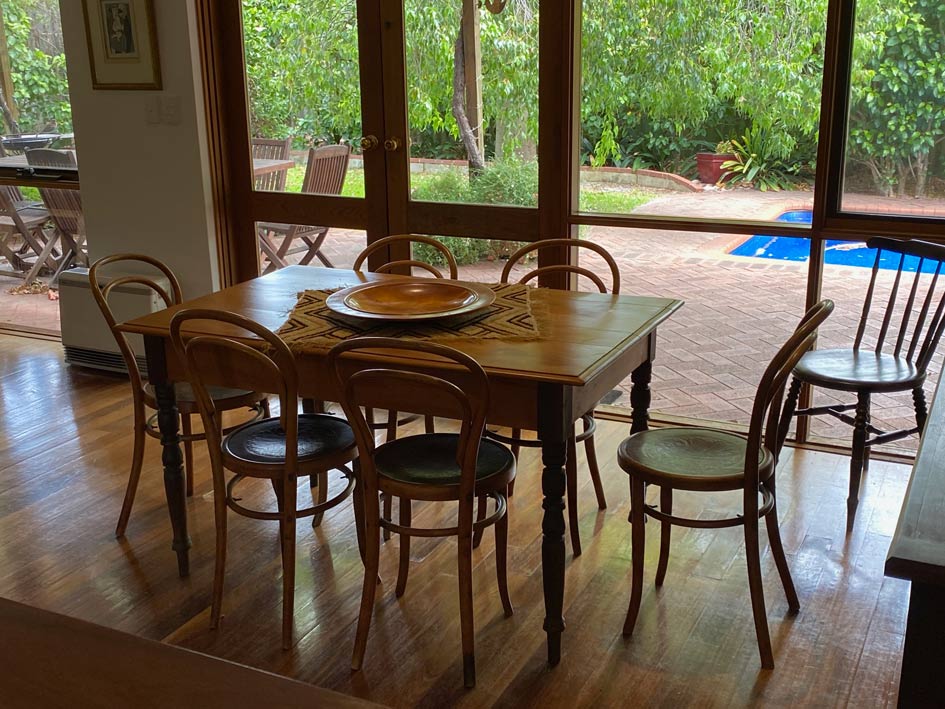
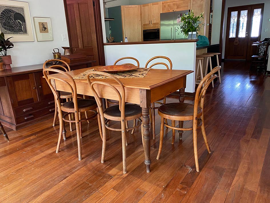
This table is over 200 years old, and has great sentimental value. It is built of Yellow Wood (top) and Stinkwood (legs). We bought this after getting married. Now, 42 years later, Lynndy wants a larger table.

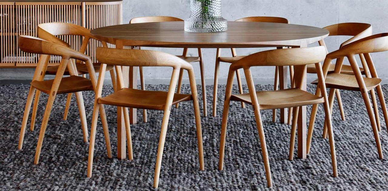
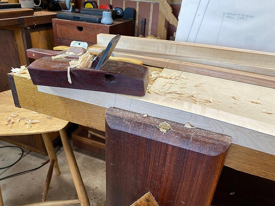
The plan is a table with a top and skirts in Rock Maple and round, parallel legs in Jarrah - very Mid Century modern. The aim is to blend two modern Mid Century carvers in Rock Maple with the bentwood chairs. Consequently, a lighter look for the carvers is needed.
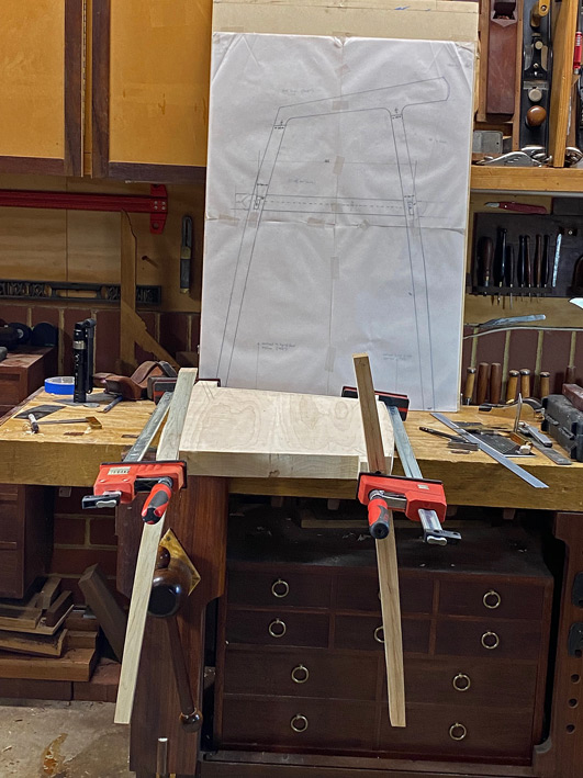
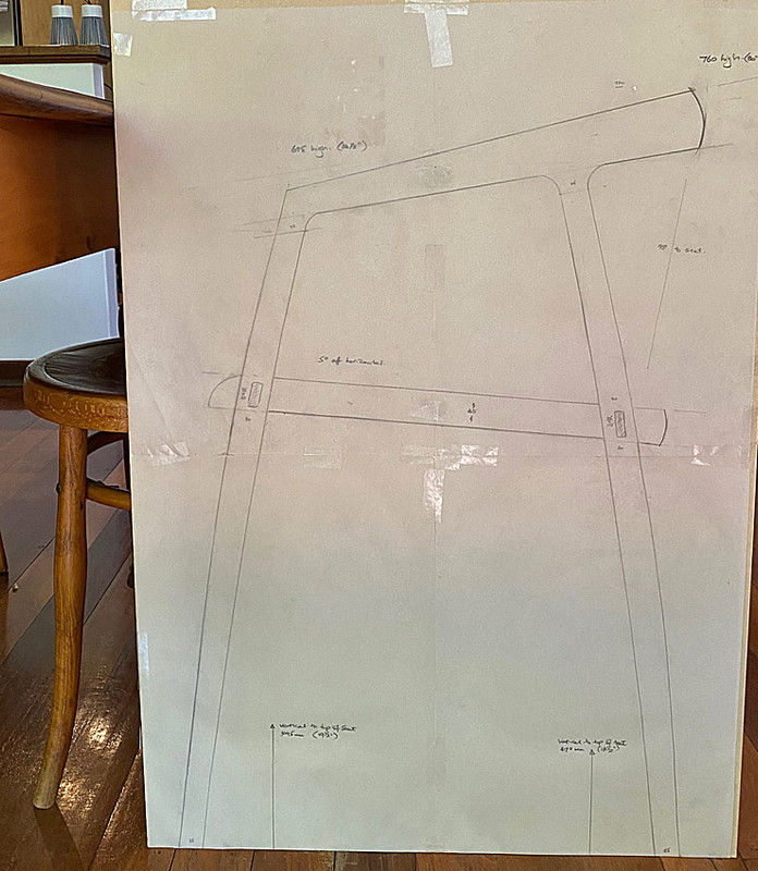
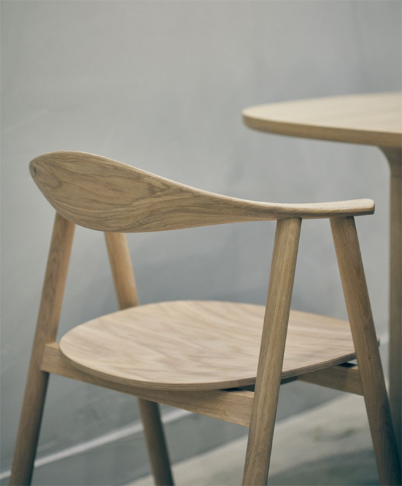
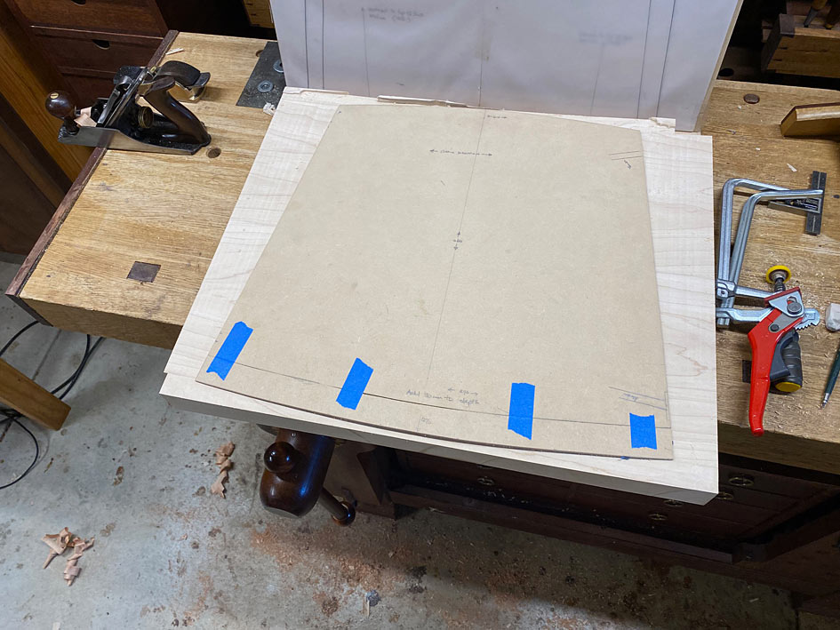
Here is the design.

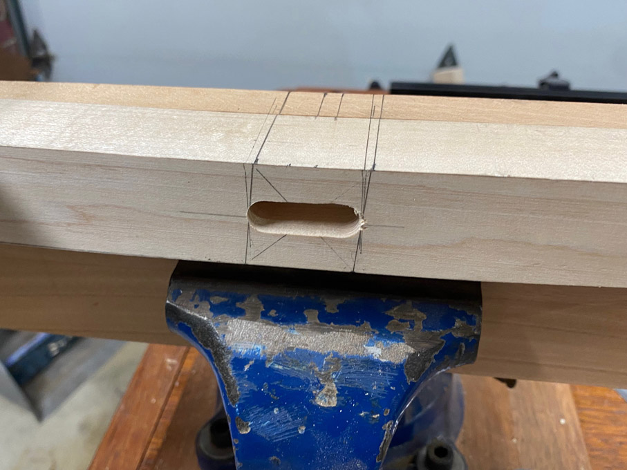
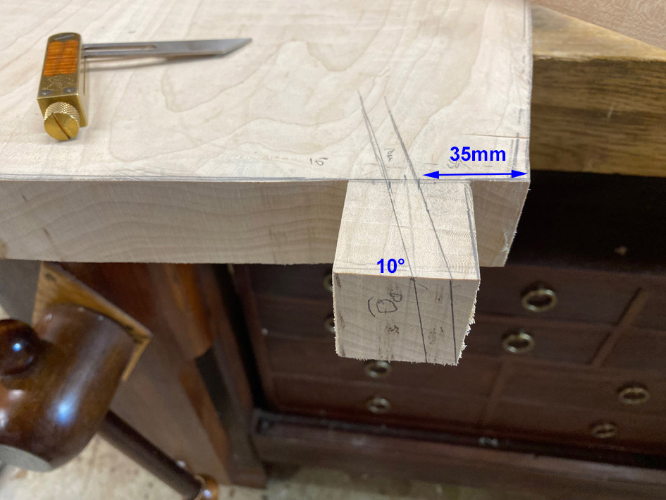
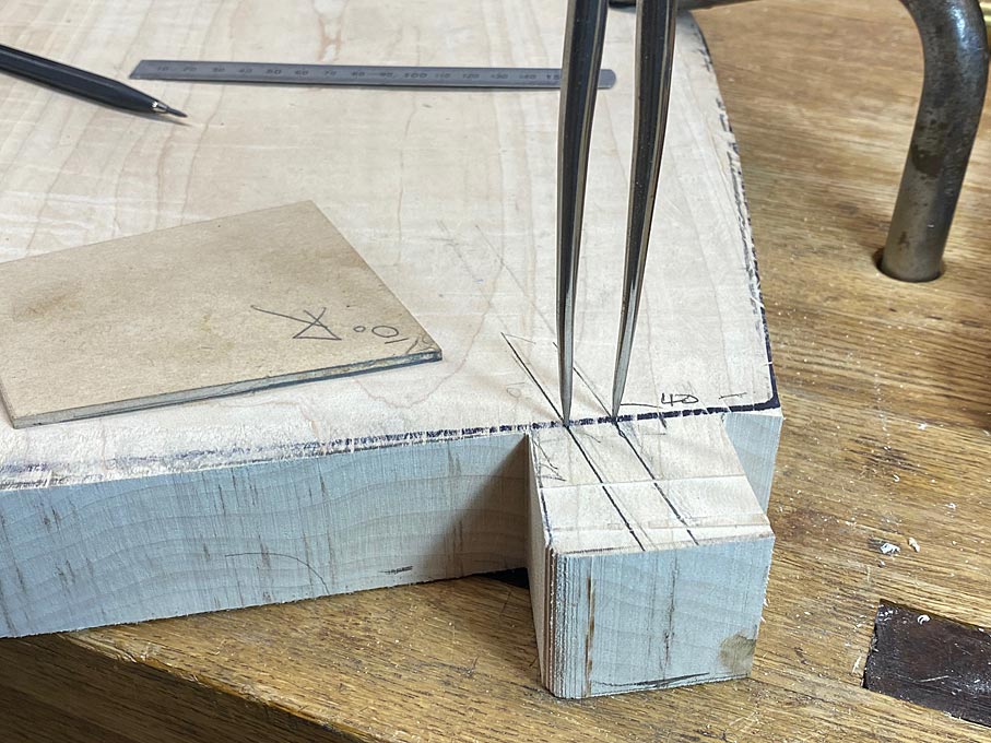
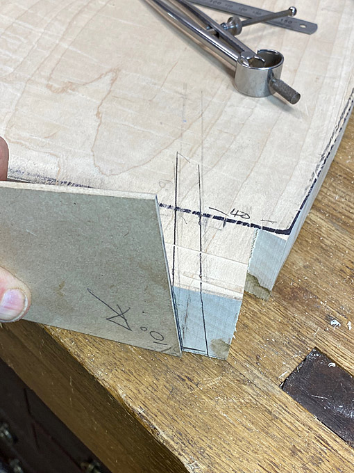
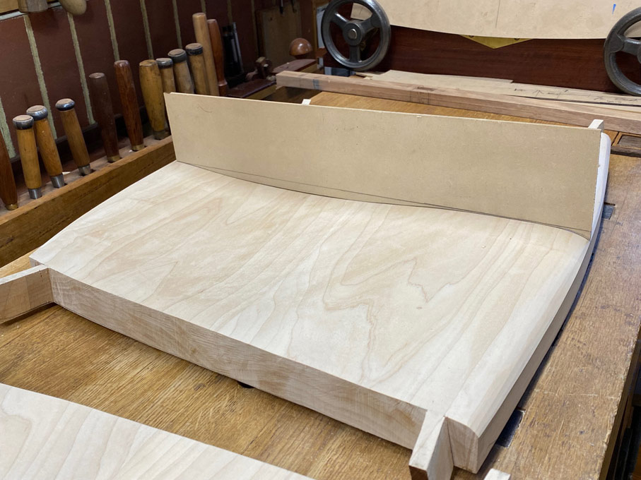
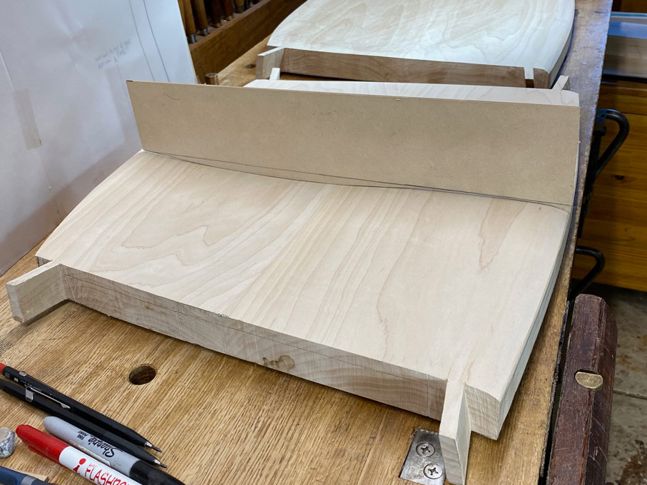
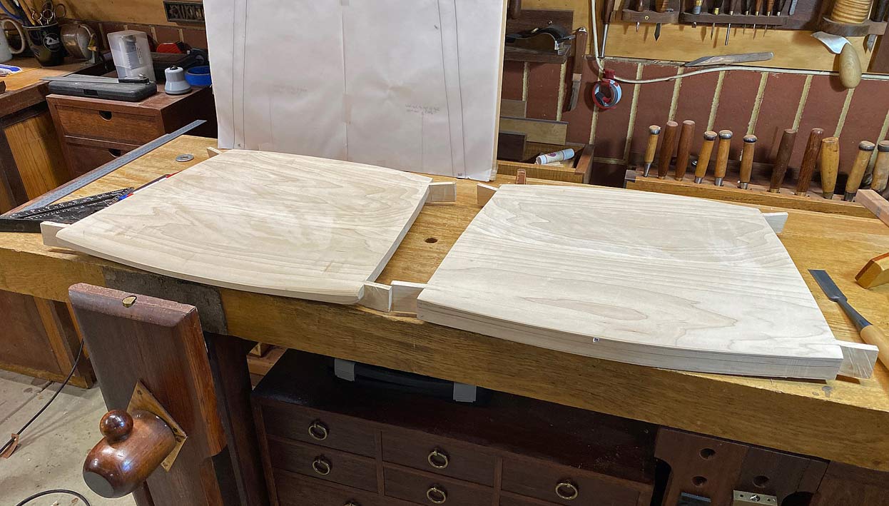
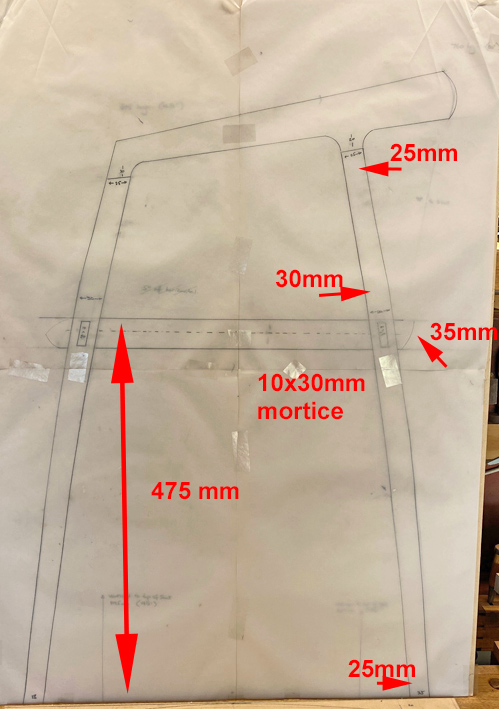
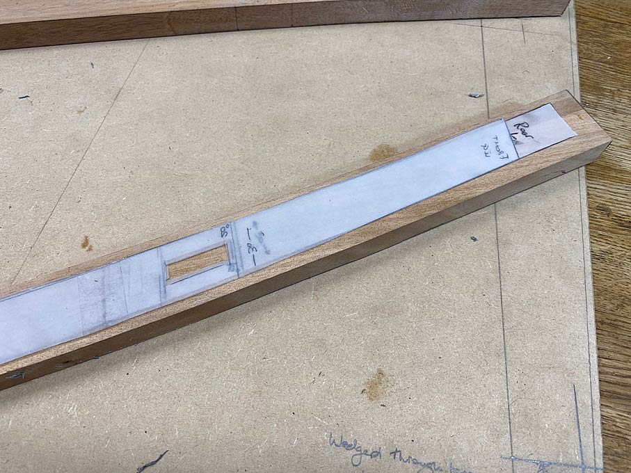
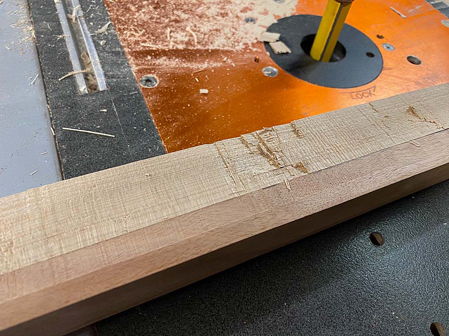
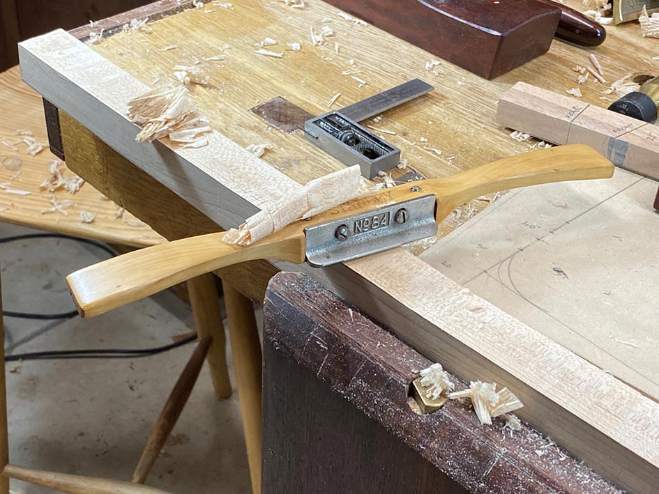
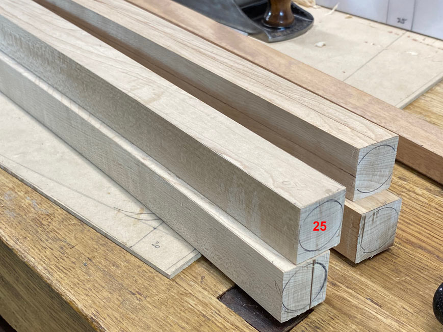
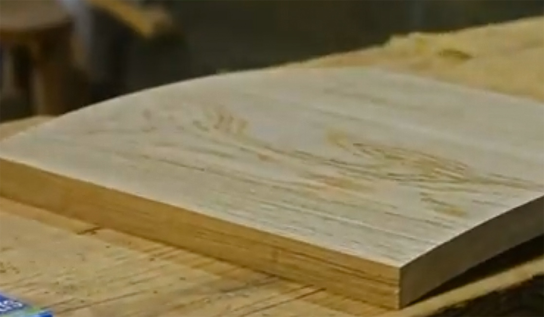
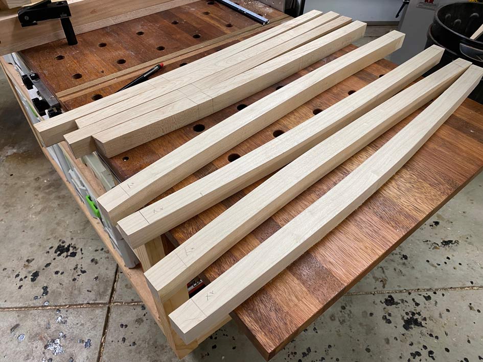
The legs are curved and round, with 25mm top and bottom, and 32mm around the seat area to accommodate the joinery. The 35mm thick seat will be attached with mortice-and-tenons (not sure yet whether integral or loose tenons). These will be 25x10mm.

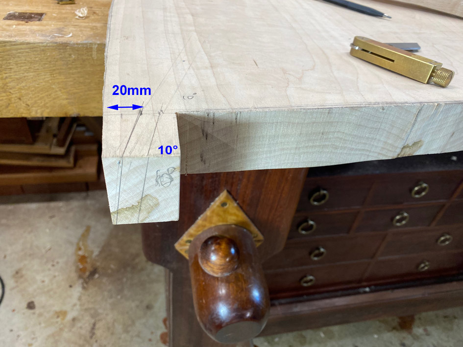
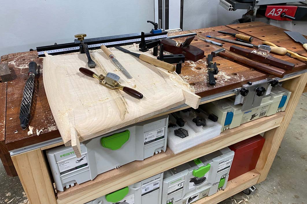
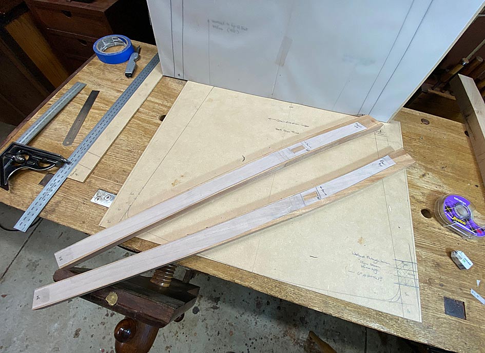
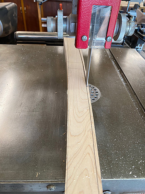
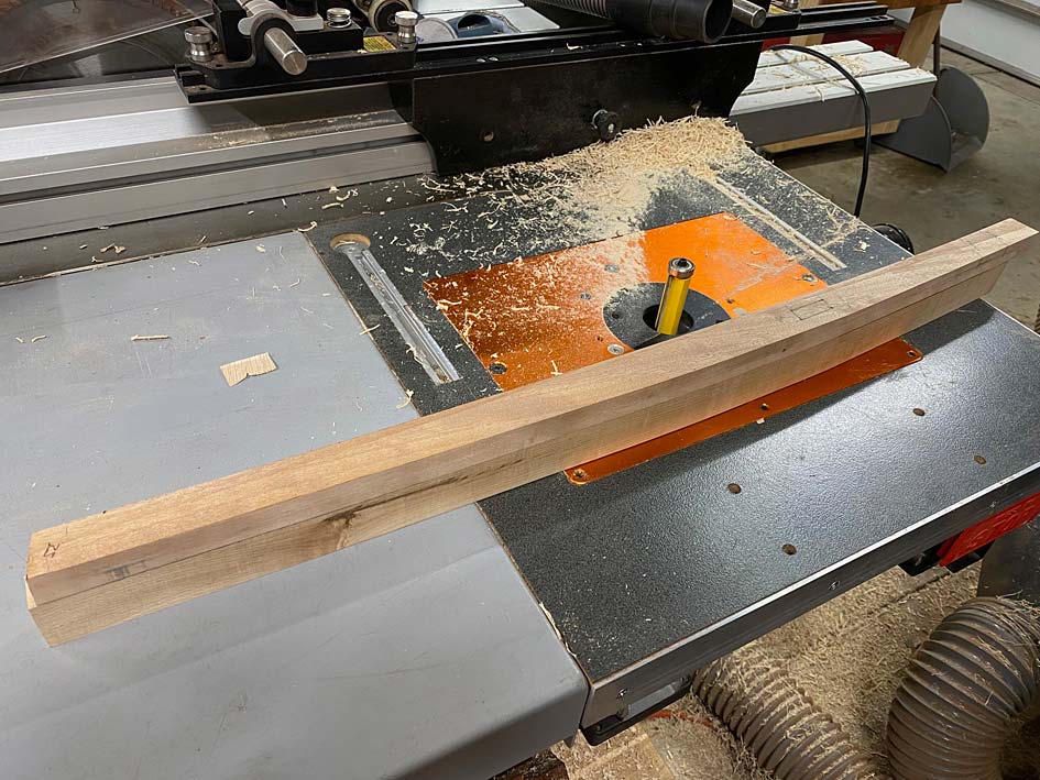
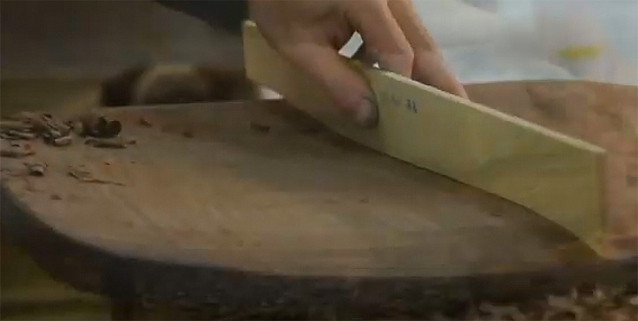
The curve in the legs is a desired feature to soften the look and also link with the bentwood chairs. The complication, in shaping, is that there is a taper and a curve.

The height of the top section has been reduced significantly. The design ...


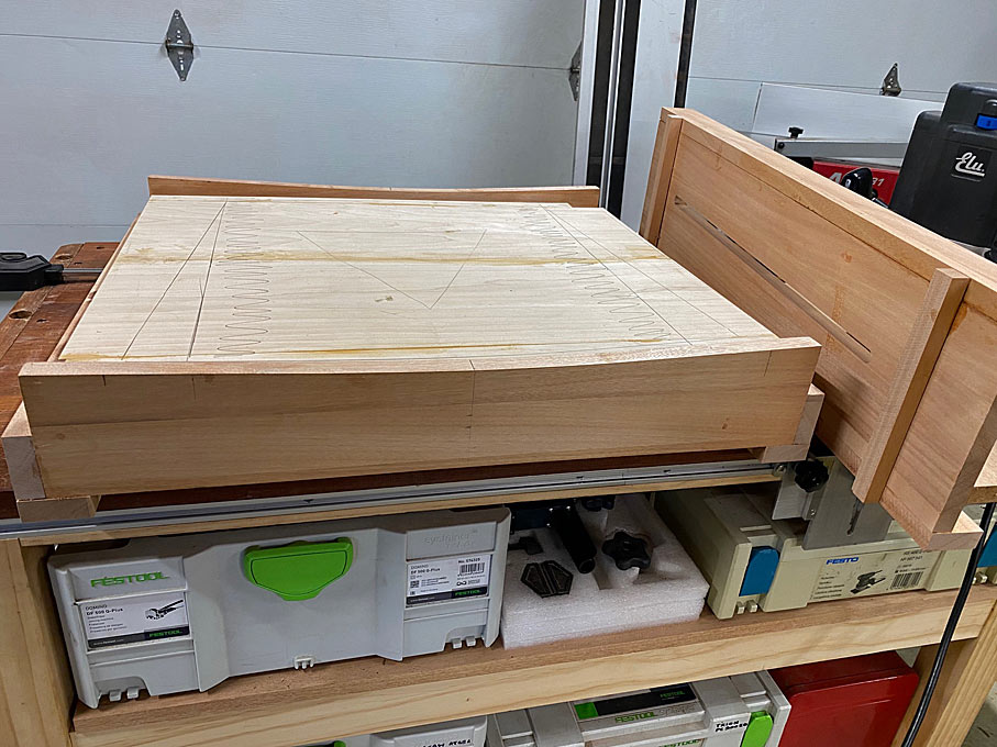
Then there are finer details being worked out, such as the curve at the rear of the backrest and seat to link with the roundness of the bentwood chairs. The transition from the legs to the arm rest is borrowed from Hans Wegner and used when I build his The Chair.

Details of importance: the seat angled at 5-degrees off horizontal, and the backrest is 95-degrees to the seat. The centre of the seat is the same height as the benchwood chairs.

The plan shape for the arm- and back rest will come later.

Thoughts?

Regards from Perth

Derek
 
Through mortices at the seat to leg joints or "nailing" it with Dominos or other loose tenon? Look forward to the end result and the journey between.

Pete
 
We have sentimental attachment to our decades old dining table and chairs too. But the carvers are the thing I would change if I could. They mandate that you can only have one person sat on the ends of the table, whereas the ends can accommodate 2 people at a push using seats without arms. So every Christmas etc I have to lug heavy unwieldy oak carvers upstairs and replace them with stools or unlatching chairs!
 
After some discussion, and a sudden increased awareness of dining room chairs, I decided to level the seat in profile ...


The seat will not end up horizontal, however, but be curved across the width, and further carved for extra depth at the butt end.

This is a basic template for the seat ...


The seat will be attached directly to the circular legs with through integral tenons for strength, and because the curved seat would make it difficult to use loose tenons. The tenon/mortice with be 10x30mm.

A tracing of the legs was used to create templates ...


In drawing the legs, each was mapped out separately, but with the same basic parameters: 25mm diameter at the top and bottom, and 30mm diameter through the centre. Similar curve plotted. The rear legs are roughly 30 mm longer than the front legs, and I anticipated that the proportions would differ as a result. However, when I placed the two templates on top of one another, they were exactly the same! And not only that, but the mortices were in exactly the same position as well!!


As a result, one template was used for both front and rear legs.

The plan was to bandsaw out each leg ...


... and then use a pattern bit on the router table to trim the waste ...


This did not go to plan. The first leg was uneventful, but the second decided to explode. This is what I feared from the Rock Maple. Even with care in regard to grain direction, and resorting to climb cuts where needed, the router bit I had available was not helpful (the router bit I ordered had not arrived, and would be some days away).


I had four leg blanks for the first chair cut out, and decided to do it in a method with which I am more comfortable ... with hand tools. Since there was so little waste to remove, a spokeshave on the inside curve was simple enough ...


... and a hand plane on the outside curve was even easier ...


It is vital to check frequently that everything is perfectly square. Morticing would not be possible otherwise.

Rock maple may be hard and brittle, but it cuts cleanly with a plane blade.

The leg blanks are 30mm thick. Once the outline is cut to match the template, the ends will need to be reduced to 25mm ...


Lastly, for now, the position of the mortice was marked on both sides of each leg. The legs will be attached with through mortice-and-tenons, and each mortice is cut half-wway from each side ...


I am putting aside these legs for now, and will return to the final shaping, along with the other four, after the seats are made. which is next up.

Regards from Perth

Derek
 
The question I have is whether to keep the ends of the mortices round, or square them off? Square ends make for easier square (hand cut) tenons .. integral to the seat), but round ends will look better - in keeping with the round legs.

Regards from Perth

Derek
 
Shaping the legs have been set aside until the seats are carved. Shaping the seats is a challenge I have been looking forward to, but I must admit that two days have passed, and there is not much to show for a lot of effort. Let's have a look at the design of the seats.

The notable feature of these chairs is that they do not have a single straight line. Anywhere. There are three design aspects ...

Firstly, the plan for the seats will be curved like these ...

CH12.jpg


However, they are to be 35mm high at the sides, and recessed like these ...

CH11.jpg


CH21.jpg


The underside must curve sympathetically with the seat ...

CH20.jpg


The third factor is that the seats will be attached to the legs with mortice-and-tenons, and will not rest on stretchers, as most chairs appear to do (and seen in an example, above). The reason for this is to increase the appearance of lightness. Shaping of the seat has to make provision for the integral tenons.

The seats are to be shaped with a combination of power- and hand tools. Power is needed .... this is Rock Maple!

I spent time building a router sled to curve the tops and bottoms of the seats. The tops are documented here.

CH14.jpg


CH15.jpg


CH16.jpg


Today was 37 degrees Celsius (99 degrees Fahrenheit), and it was HOT in the unconditioned workshop, all windows and doors closed to be kind to neighbours. And it was slow going pushing the router back-and-forth. Plus it was messy ..

CH17.jpg


This was the result of my labours: two boards with the initial curves on their tops. These boards started out at 50mm thick.

CH22.jpg


There is a template for the basic shape. This is simply to position the tenons. The outline will be modified later ..

CH19.jpg


The section for deeper hollowing is marked out, and a grid created to position 10mm holes through the centre and 5mm holes at the sides to guide waste removal ...

CH23.jpg


A scorp was used to remove the bulk of the waste ...

CH24.jpg


This was hard work - the Maple is hard stuff - and the next seat will use a different method. That will be revealed in the next post.

Shaping is done with travishers. I have two I built with different radius soles. This is one ..

CH25.jpg


The result of my labours .... across the width ...

CH26.jpg


And through the centre ...

CH27.jpg


Lots of shaping still to be done at the front and underside.

In addition to the hollowing of the seat for comfort, the extra depth at the rear creates an effect tilt towards the rear legs. The amount of seat tilt can also be adjusted via shortening legs, if needed.

More soon.

Regards from Perth

Derek
 
Here in Blighty, you’re making me very envious of warmth! It’s hovering just a tad over zero, wet and windy.
Lovely work, always a pleasure to read your threads.
 
🥶 -31ºC, sunny, with wind chill of -41ºC here this afternoon.
I think if I stepped into +37ºC right now I would pass out and be a raisin in the middle of a big puddle.
I also enjoy looking at Derek's threads.

Pete
 
The initial carving of the second seat ... time to learn something from the initial carving of the first seat! Rock Maple is bloody hard stuff. I have used a scorp to quickly carve Pine and Tasmanian Oak. I used a scorp to scoop out the first seat, and it was not fun in 37 degrees Celsius (98 Fahrenheit). Well today it is 39 degrees Celsius (102 Fahrenheit). Time to try something new.

Here is the second seat, which has been curved on the router sled ...

CHH1.jpg


My 74th birthday present (3 days ago) was an Arbortech Turbo Plane kit ..

CHH2.jpg


This can be set up in three ways: it can plane/joint rough boards, it can sand boards, and it can carve ...

CHH3.jpg


It has variable speed, but I found carving is best at the fastest rate. Most importantly, it has some of the best dust control one can imagine. There is barely any chips to be found.

CHH4.jpg


The Turboplane was impressively fast in taking the surface down to the drilled depths ..

CHH5.jpg


It is an angle grinder, and noisy, but less so than a router.

I mentioned that is is a sander as well. I took the opportunity to try this out. 60-grit was rapid, and left a surface as smooth as a baby's bum.

CHH9.jpg


The second new tool used was one I made ... literally in about 10 minutes at this point in time. I had a small coffin smoother, about 4" long, with an open mouth and a single iron. It had been purchased in an "antique" shop for a few Dollars several years ago for the express purpose of turning it into a chairmaker's plane. I admit - I procrastinated ... until today. These are curved front-to-back and side-to-side. It was not much work, and this is what materialised ...

CHH7.jpg


The iron was rusty, and simply flattened on the side of a 180 grit CBN wheel, and then shaped to match the curve of the plane. You can see that the camber is more like a jack plane than a scrub.

CHH8.jpg


How did it work? Brilliantly! Really, after using the travishers, this plane left them in the dust ...

CHH11.jpg


There are a couple of red arrows in this photo. The upper one points to the added curved side lines. The seats were temporarily made with straight sides, but they will have a slight curve (no straight lines on the chairs). The second red line points to where the front of the seat ends. It will be cut off at this line.

The photo below shows the outline of the seat prior to the underside being curved in the router sled. Note the sections left for the tenons, and the red lines here represent the angle these will be (20 degrees at the front and 10 degrees at the rear) ...

CHH12.jpg


Finally, the router sled was converted from convex to concave ...

CHH13.jpg


That is for tomorrow.

Regards from Perth

Derek
 
Andy, on the a different place forum, left a message which was remarkably predictive of what I had planned to write.


For me, the interest is in the problem solving. To make a single chair, with all parts curved, would be a challenge. But to make a matching set, you are going to need a tight system of reference edges and surfaces, to be removed only when all shaping is complete. Your methods so far make sense - of course they do! - I just mean that it sometimes takes me a minute to catch up and see why you are making a part the way you are. I'll be happily admiring the rest of the build.

Andy, spot on! In fact, you preempted the very topic I planned to write.

Everything in furniture building requires forward planning. This is even more the case where, as here, these chairs have not been built before, do not come with plans, and are based on sketches I have made. One sees chair builds on YouTube where the Maker lays out a template, cuts it out, finishes it with a template router, and then starts glueing parts together. If only ...

When one looks at the chair design, attention is taken by the arms and back. Yet these are aspects which will be approached last. Far more important is the seat, since this creates the plan for the arms. But, building a seat like the one envisioned is complex as it has two shaped sides, a top side and a bottom. Most seats are carved only on the top, with the underside being left flat.

In addition, I have seen very few seats which are attached directly to the legs. Almost all rest on stretchers, with the stretchers morticed to the legs (e.g. The Chair). The latter is easier to construct as you build two sides, and then link them. With integrated tenons in the seat, one has to make allowance for the tenons, and these need to be cut at the correct angle before the underside of the seat can be shaped. The reason for this is that we need a flat reference edge to mark the tenon angles (which come from the drawing).

Here is the seat at the end of the last post ...

CHH12.jpg


The underside is flat at this stage (being the reference sides), as are the sections where the tenons will project. But ...

While I am confident about the angle of the tenons, I want to be sure of this, and this requires that the legs be clamped to the ends of the seat at the angle predicted. The legs have been left flat - not yet rounded - as it is easier to add a mortice at this time.

So the next stage is to do just this, but I only have legs for one chair. As a result, work stopped to complete the other four legs. First, a section was cut off one of the 3m long (x 250mm wide x 50mm thick) Rock Maple boards (my wife helped me load this!).

Easier to crosscut on a MFT with a tracksaw than a tablesaw. Mine is a 20 year old Festool I purchased about a year ago in as-new condition.

Tools1.jpg


The section was re-sawn to 32mm and then planed to 30mm. Great tracking by the combination of a Hammer N4400 (which I have had for about 15 years) and a 1" Lenox Woodmaster CT blade ...

Tools2.jpg


Tools3.jpg


As I mentioned in an earlier post, it is less stressful to mark the legs with a template, bandsaw to the lines, and then use spokeshaves to clean up. Here are some of the spokeshaves I use ...

A Stanley #84 boxwood spokeshave excels in taking thick shavings. This is where I begin ...

Tools4.jpg


Veritas make a copy of this in the form of their LA Spokeshave, and it is very good (I use one or the other, not both) ...

Tools5.jpg


Many years ago I was gifted a flat and round spokeshave by Terry Gordon (HNT Gordon tools). It is a Malaysian/Asian design with a high cutting angle. This is my go-to if there is any reversing grain ...

Tools6.jpg


Lastly, the LN Boggs spokeshave takes very fine shavings and is used like a smoother to finish the surface ...

Tools7.jpg


Here are the completed leg blanks ..

Tools8.jpg


Tomorrow I will mark out the tenons.

Regards from Perth

Derek
 
Especially after today, this build really feels like a step forward, a step sideways, and then a step forward again ... cha cha cha ..

I really do know where I am going, and what has to be done, even if it does not seem that way! :) Templates would have made the process easier.

So where are we up to? Well, it is the stage where the through mortices are made. We start with 8 legs ..

Legs1.jpg


The mortices will be made with a Domino ...

Legs1b.jpg


Then it gets a little complicated :

1. The legs are curved.
2. The mortices are cut half way from each side, and must be aligned well to meet in the centre.
3. The Domino can cut a maximum of 24mm width. The mortices are 30mm wide (by 10mm).

I have a guide for setting up the Domino to cut a specific size mortice width. This is for a 10mm x 24mm domino. Since the legs curve, the boundary lines for the mortice angle. The boundary lines cannot be dropped down on the vertical, so ...

First set the left side centre indicator ..

Legs8.jpg


.. and then the right side indicator ...

Legs9.jpg


Two plunges of the Domino creates this ..

Legs1a.jpg


Repeat on the other side.

With all 8 legs morticed, I began to lay out the tenons.

All the legs are angled at 10 degrees towards the centre. This is prior to cutting the tenons ..

Rear leg ...

Legs-10.jpg


Front leg ...

Legs-11.jpg


Here is the mock up with the plan/drawing in the background ...

Legs-12.jpg


And a close up ..

Legs-13.jpg


A last photo for today - taken from the rear. The ears represent the stock for the tenons ...

Legs-14.jpg


Tomorrow the tenons will be cut, and then we can get back to shaping the seats.

Regards from Perth

Derek
 
Time to saw the tenons.

I have gone back-and-forth on doing it this way. I can understand why so many builds use loose tenon joinery. Simply, it is easier to do so than creating integral tenons. It also makes it possible to shape the seat fully separately, especially the perimeter. The seats here have been roughly cut to shape, and only the top partially sculpted. It has been a very round-about way of building ... more steps that could have been avoided.

So why build this way? Well, I want integral tenons as they will be stronger than loose tenons. It is also difficult to rout the mortices in the edge of the seat owing to the awkward angles involved. Lastly, adding mortices may not be possible owing to the reduced depth of the sculpting.

The tenons are not straight-forward as they angle inward at 10 degrees, creating compound angles, as will be seen shortly ...

T1.jpg


Using a template for 10 degrees, the angles for the tenons were plotted on the ears ..

T2.jpg


Dividers are used to mark the 10mm width ..

T3.jpg


There is also a 10 degree splay angle to add ...

T5.jpg


At this stage my spatial-ability challenge came to the fore and I was in over-load with angles. Marking out the angles on the reverse side gave me the biggest headache, and I came so close to accepting loose tenon joinery!

I decided that loose tenon was always a backup, and so just go for it. The saw used is a 16" Wenzloff & Sons tenon saw (10 tpi rip). It is a HUGE saw, but worked really well here with its aggressive cut.

T6.jpg


T7.jpg


Cutting to the line, which left just a smidgeon of waste.

Waste removed with a Ryoba ...

T8.jpg


All tenons cut ...

T9.jpg


I checked several and all were on the money at 10 degrees. I'm a happy camper ...

T10.jpg


Eight tenons and eight mortices ...

T11.jpg


Next on the agenda: rasp the perimeter to shape, finish the tenons while there is still a flat reference (under) side, and then shape the underside of the seat.

Regards from Perth

Derek
 
We ended up last time with the sides cleaned up and the tenons cut to angle ...

T11.jpg


The tenons were now sized to correct width ...

TT2.jpg


... pared ...

TT3.jpg


.. and rasped to width ..

TT4.jpg


I made a template to ensure each would later be a tight fit ...

TT6.jpg


So now we have two chair blanks with a semi-shaped outline, a profiled upper side and four sized tenons ...

TT7.jpg


Now it was back into the router sled to shape the underside, which was to curve in parallel to the upper side ...

TT8.jpg


The result was two of these, after some cleaning up with a jack plane ...

TT12X.jpg


Time to give the seats their final plan shape. The seats were flipped over ..

TT13.jpg


And a template used to mark the new rear curve ..

TT14.jpg


TT15.jpg


One of the problems photographing this Rock Maple is that the light colour does not show details particularly well. Especially the seat hollows and internal curves. In addition to the upper curve, the seat is hollowed out to a depth of 18mm.

TT19.jpg


TT21.jpg


Nothing to see here. But ... from the sides ... one then the other ...

TT22.jpg


TT23.jpg


Note that the carved seat adds a 4 degree slope to the seat, which is what is in the design (however the original drawings missed it coming from carving seat, and adjustments had to be made).

We are closing in on the last lap for the seats - well, next to last lap (it seems to go on forever!). The undersides need to be shaped to remove the bulk (which was needed for the tenons), and create a sleeker presentation. Back to the Arbortech carver to remove the waste ...

TT24.jpg


TT25.jpg


I frankly do not know how many hours this saved if I had been using hand tools. I did try a razor sharp drawknife, and the Rock Maple laughed at it. The Arbortech is terrific. It does take a little while to get the feel for gentle carving, as it can run away from you if you carve with a climb cut.

Spokeshaves next, and the Veritas LA does a magic job ...

TT25-1.jpg


To get the best out of this spokeshave (since many described it "diving" into the wood), it is important to understand that the toe is curved 4 degrees from the mouth (as is the Stanley). Think of this in the same way one uses a travisher, which has a similar toe: The angled mouth acts to open or close the mouth. Set the blade and then adjust the depth of cut when using the body - toe down and it cuts a fine shaving, pressure on heel and the shaving is thicker. I suspect that "diving" occurs when the shaving is thicker, and attention is not given to grain direction.

The tenons are at the centre of the design. The seats started out at 50mm thick. They are down to 35mm at the centre, and will end up about 15mm thick at the surrounds. However the tenons must end up 30mm high.

Here the tenons are being "extended" from the seat, with two saw cuts ...

TT26.jpg


TT27.jpg


The spokeshaving of the first seat is done, and alongside an unfinished seat for comparison ...

TT28.jpg


TT29.jpg


Working on the second seat at the close of the day ...

TT30.jpg


Regards from Perth

Derek
 
I fitted the legs then decided that the seats made were not good enough. There was run out at the tenons which placed them at risk or breakage. So ... deep breath ... they are canned. The tenons will be re-made with loose tenon stock, where I can control the grain durection.

Sometimes it is an ill-wind that blows good. I am now rather pleased I am remaking the seats as I have found better info on the original chair, and details of the seat design. I have the legs right but not the seat.


In the mock up at the factory, the seat was screwed to the legs, but the final version used mortice-and-tenon. These joints are made very solid by a great deal of supporting mass around them. I plan to make the joints loose tenons for extra strength, but try and follow the original design in this regard. (At this stage it is a toss up whether I copy the arms or go with a design I think is more elegant).


Here is a video I found of the build:


The chairs are sold in Oz for $3600 each.


Regards from Perth


Derek

Never been so happy to have a mute button, interesting vid though, especially seeing the level of CNC involvement in what is likely a small production number item. $3.6k per chair, wow, good business if you can get it.

Painful to have to bin something you've worked on but sounds like it was the right decision at the time.

Great thread, and as always in awe of what you are making, one day I'll get past straight lines and right angles.

Fitz
 
Thanks Derek, it's all coming together and sadly I now have an unfounded need for an industrial clamping machine that makes whooshy air noises!
 
Back
Top