A simple sharpening Jig for anyone.

UKworkshop.co.uk

Help Support UKworkshop.co.uk:

This site may earn a commission from merchant affiliate links, including eBay, Amazon, and others.

santiniuk

Established Member
Joined
12 May 2007
Messages
99
Reaction score
0
Location
Darlington
Hi,

Continuing from a previous thread I thought I'd post an idea that I hope would be suitable for anyone to make.

Again it uses some of the fundamental ideas that Chas posted but really is as easy as could be to make. (I think!)

For me with different diameter tools I would prefer to have dedicated jigs that can be adjusted as the tools wear rather than to adjust for different gouges.

So...

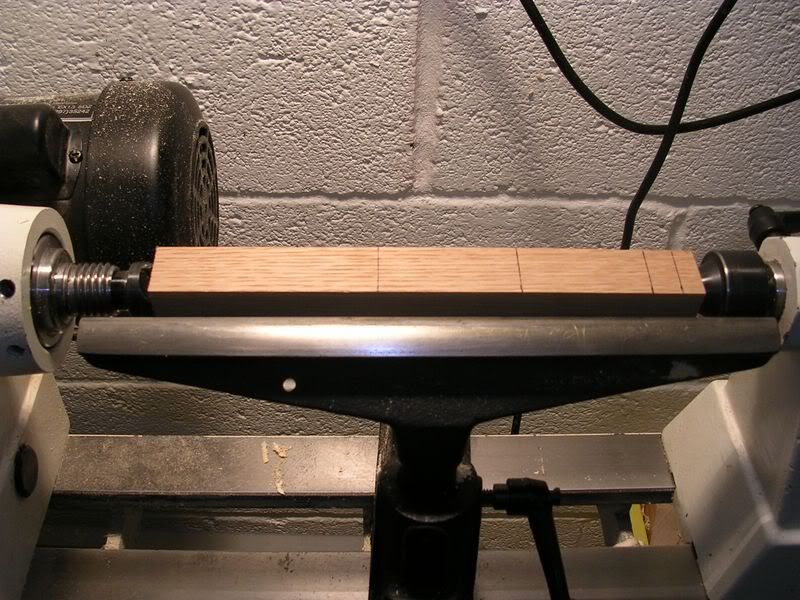
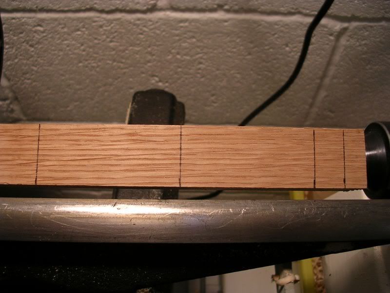
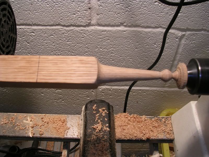
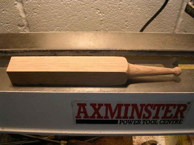
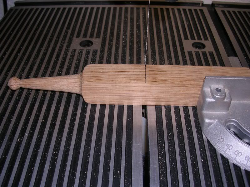
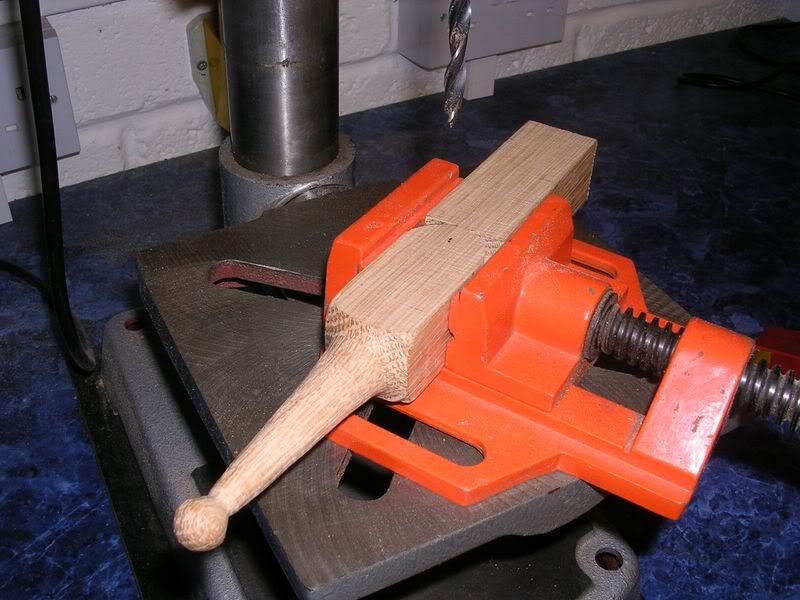
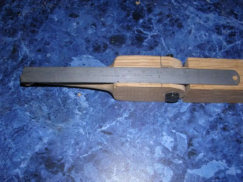
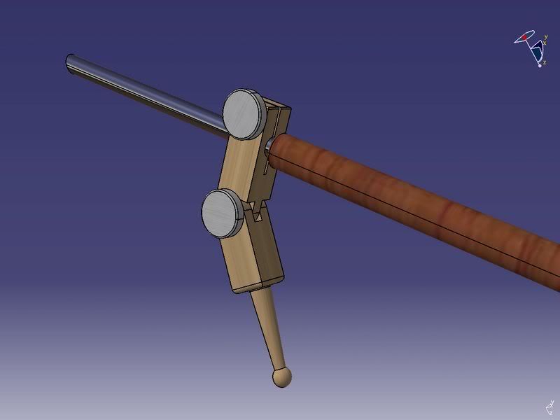
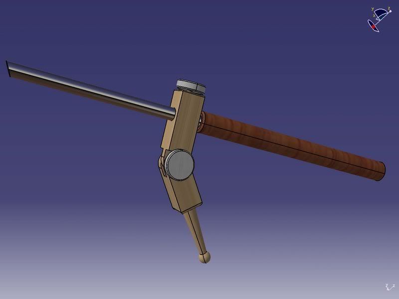
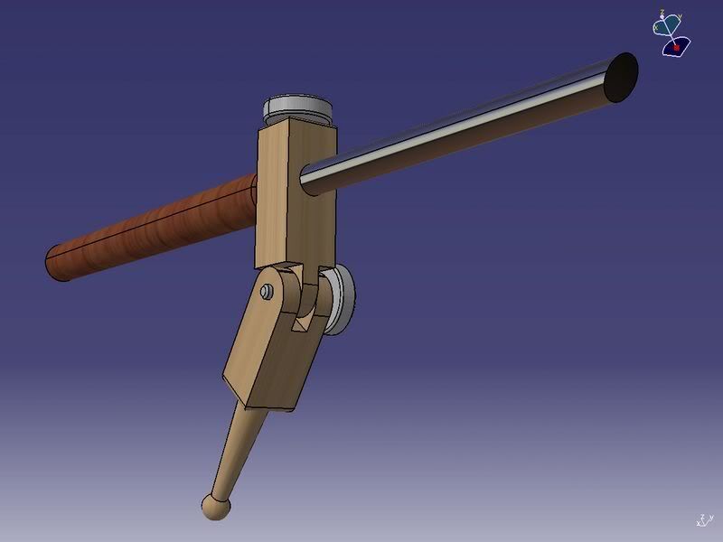
Take a piece of 25mm * 25mm wood and turn between centres the tapered post section including the 13mm ball at the bottom.

8800x600.jpg


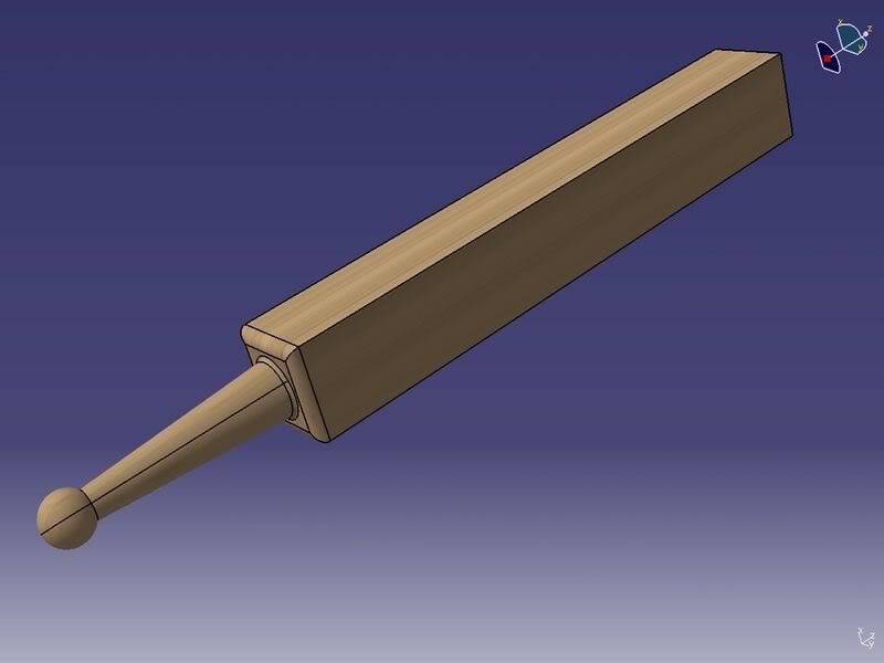
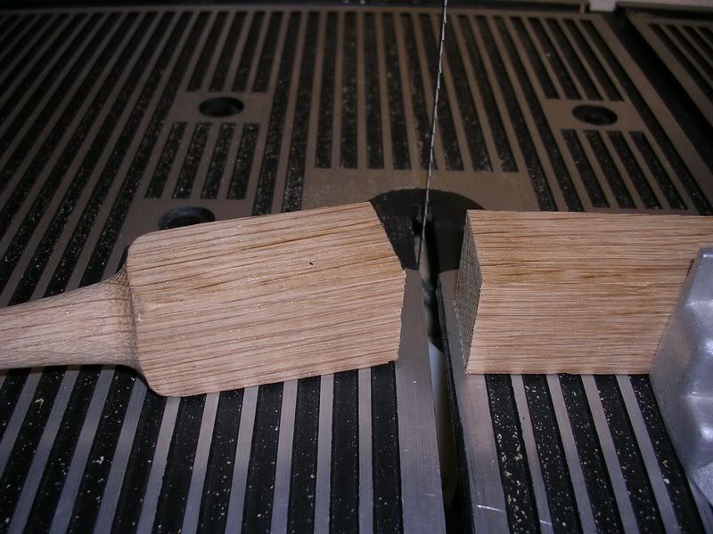
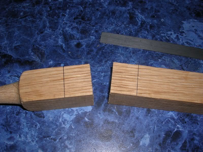
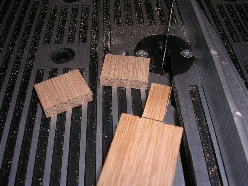
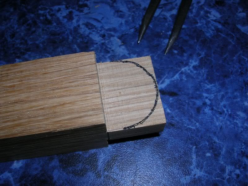
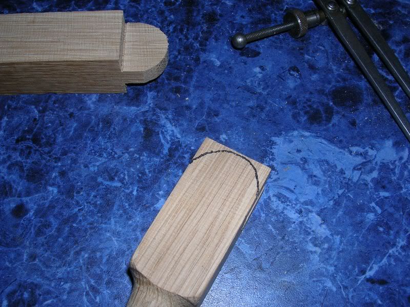
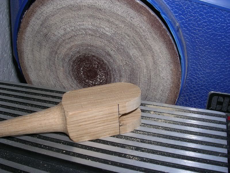
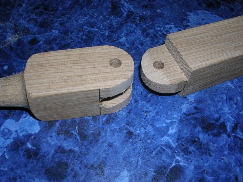
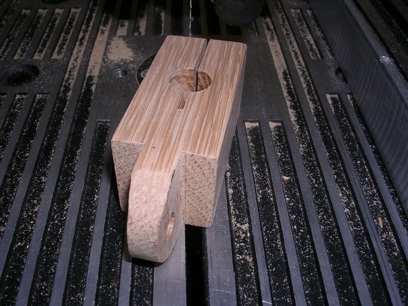
Remove this and cut in half. Giving us the post and tower section.

2800x600.jpg


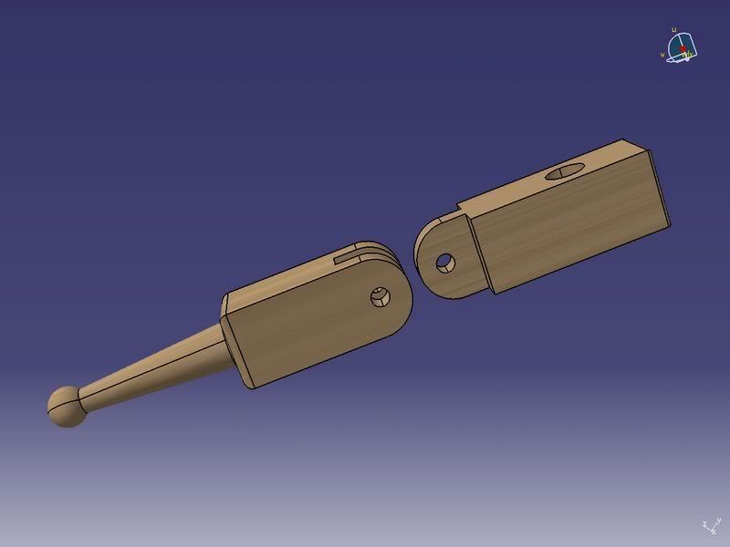
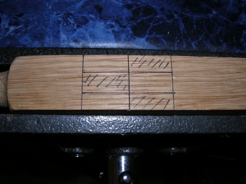
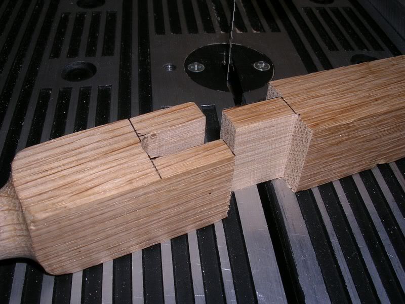
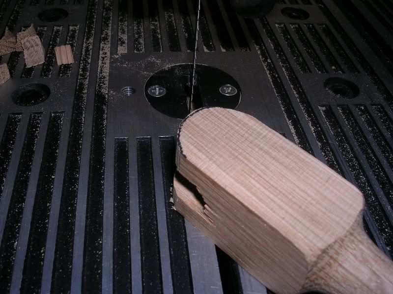
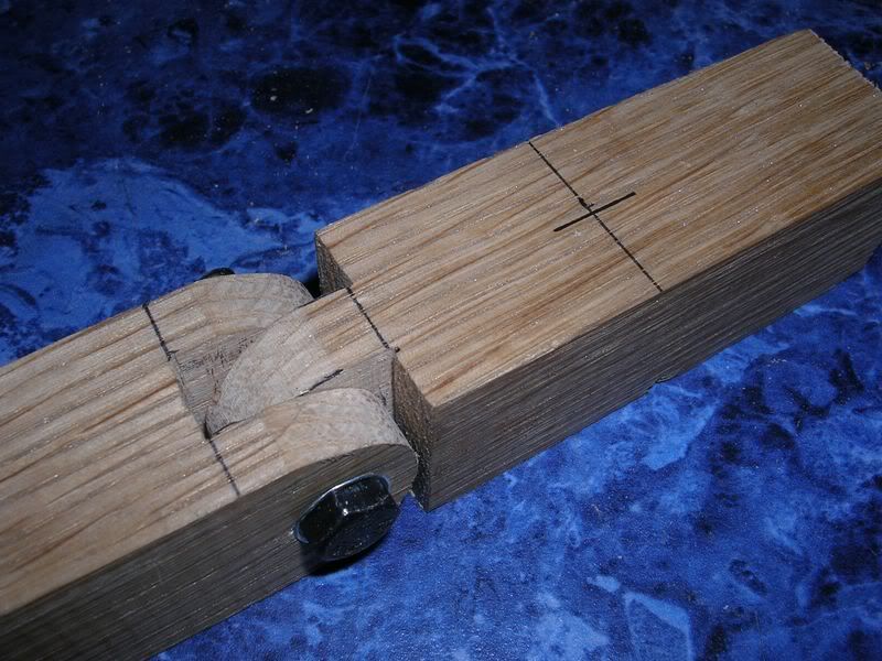
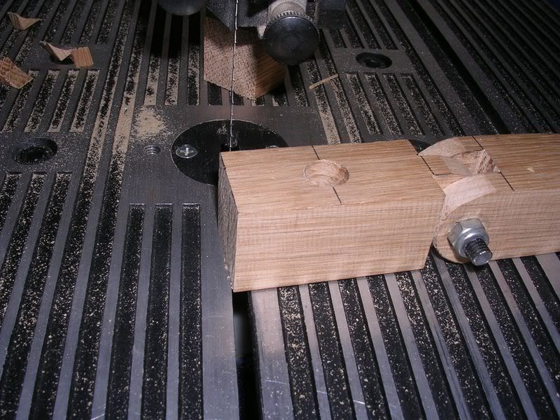
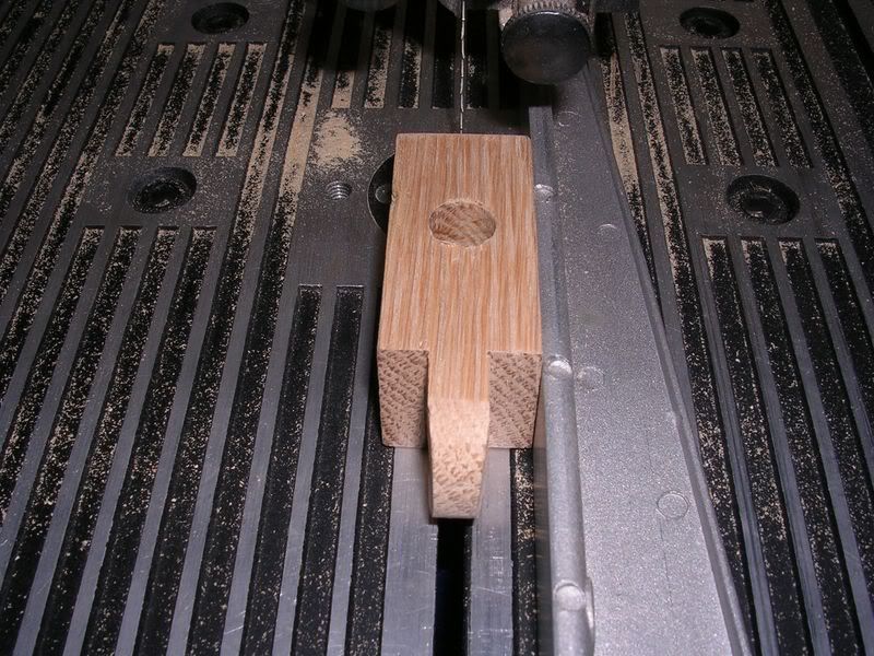
Notch the tower and post out. A bandsaw would be ideal for the slot.

1800x600.jpg


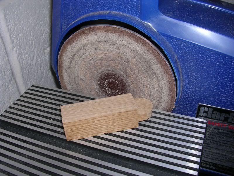
On the tower stem round over to ensure it rotates free in post.

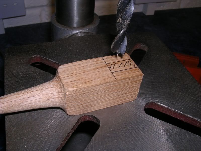
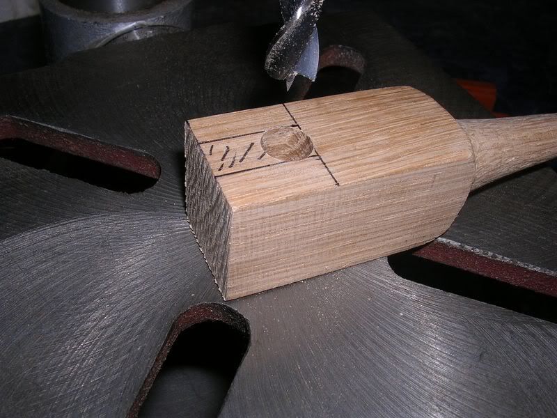
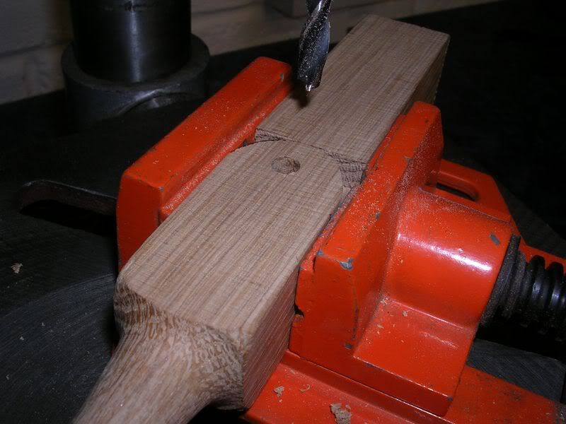
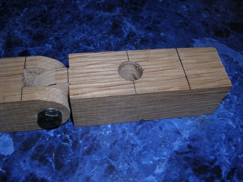
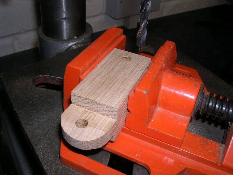
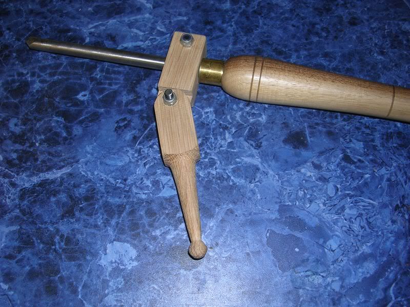
Push them together with a small gap at the bottom and drill a 6mm hole through pivot joint

Then drill the tower to a hole suitable for your gouge. And for the clampdown knob.

3800x600.jpg


Using 6mm threaded inserts for the pivot joint and clampdown knob assemble together.

4800x600.jpg


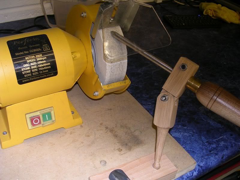
Adjust pivot knob to suit required angle. And use clampdown knob to hold gouge in position.

5800x600.jpg


6800x600.jpg


7800x600.jpg


I have yet to build one but will have a go this week.

Cheers

Shaun
 
Like Stu said Shaun, =D> =D> =D> now you just need to turn your CNC mill into a 3D replicator and you can turn then out by the dozen. (hammer) (hammer)
 
I'm with the rest, great CAD work. With those detailed drawings looks like your wasted at woodturning :lol: Or is that your job?
 
CAD is one programme that I have never got my head around. I stand in awe of any of you who can produce drawings like that, both the skill and the simplicity. =D> =D> =D> =D>

Pete
 
:oops: :oops: :oops:

Well thanks chaps, just trying to add a little contribution to help fellow beginners.

I cannot put into words how much the Jig that Chas posted has helped with the sharpening. I just love the clean finish it gives with just one or two sweeps from side to side.

Work has been a bit heavy this week so I have just chilled out on a night and not got round to much turning or building this jig. And I'm just about over the depression of last night's football result :cry:

I'm an electrical/electronic engineer that knows enough on the CAD side to be dangerous ! I don't scratch the surface of the detailed work my colleagues do. I use it for basic PCB / component layout modelling but it's amazingly easy to produce the images above. Program is called Catia.

Hope to build the Jig at the weekend and get some dimensions added.

Cheers

Shaun
 
santiniuk":yr90lz9z said:
...I'm an electrical/electronic engineer that knows enough on the CAD side to be dangerous ! ....

I know the feeling, some years ago I was sent on a CAD training course at Bristol Uni. (something or other 4000 system I think) so that we could work with the machine at RAE Farnborough, my main contribution was to get the wiring connected at our end of the land lines and talking, + a lot of hours spent with the rest of the design guys trying to work out how we could transfer designs and drawings between existing hand draughted sheets and machine.

Surprising how inaccurate a pencil line or metalbashers idea of a fit can be when you are trying to talk to a computer.
 
Many true words said there Chas :)

Well I thought I'd better actually prove the jig worked. It would be quite embarrassing to find it didnt :oops:

As It's aimed for the beginner I grabbed a few pics that hopefully that make it as easy as possible to follow.

Here goes...

DSCN1553800x600.jpg


DSCN1554800x600.jpg


DSCN1556800x600.jpg


DSCN1557800x600.jpg


DSCN1558800x600.jpg


DSCN1559800x600.jpg


DSCN1560800x600.jpg


DSCN1561800x600.jpg


DSCN1562800x600.jpg


DSCN1563800x600.jpg


DSCN1564800x600.jpg


DSCN1565800x600.jpg


DSCN1566800x600.jpg


DSCN1567800x600.jpg


DSCN1568800x600.jpg


DSCN1569800x600.jpg


DSCN1570800x600.jpg


DSCN1571800x600.jpg


DSCN1572800x600.jpg


DSCN1573800x600.jpg


DSCN1574800x600.jpg


From here we measure 150mm from the ball centre to hole centre for gouge.

DSCN1575800x600.jpg


DSCN1576800x600.jpg


DSCN1577800x600.jpg


DSCN1578800x600.jpg


Note change in original design direction

DSCN1579800x600.jpg


DSCN1580800x600.jpg


NewDesign800x600.jpg


DSCN1581800x600.jpg


DSCN1582800x600.jpg


Looks like I got a bit carried away with the pictures !

As you can see the design has changed from the original post. I didn't have any inserts and thought these are probably not in most peoples toolkit. I actually prefer the new design as it gets a really good clamp around the gouge stem. Basically the tower is slitted to allow the two halves to clamp from the side with a knob instead of the top.

The last picture needs the positon of the pocket positioned to allow the gouge to position better.

I can now say that after using it, that it does actually work and produces a good finish.

Can it get any easier ?

Cheers

Shaun
 
Good posting there Shaun, as the aim is to produce something simple enough that they can be left adjusted to individual tools the split clamp works fine, the top positioned locking screw might be more advantage to someone with differing gouge shaft diameters that is prepared to adjust the pivot angle.
 
Back
Top