


CHJ
Established Member
Objective:
1. To make an alternate style Fingernail & Bowl Gouge grinding Jig. (see previous limited adjustment version)
Reasons:
1. Need of an additional Jig to cover more diverse profiles, and explore different techniques.
Design criteria:
1. To provide the equivalent function of the commercial units.
2. To do it with components/materials readily available in a wood shop.
Materials used:
1. 2 pieces of Beech of 20 X 20 X 300 mm section. Main Rails
2. 2 pieces of Beech of 20 X 20 X 150 mm section. Bench Guides
3. 1 piece of Beech of 45 X 55 X 20 mm section. Tool Clamp
4. 1 piece of Beech of 45 X 55 X 10 mm section. Tool Clamp
5. 1 piece of Beech of 20 X 20 X 150(130 finish) mm section. Adjustable Pivot
6. 1 piece of Beech of 20 X 46 X 120 mm Support Up-stand. See later note.
7. 115 X 68 X 4 mm metal plate. (5mm Birch Ply as alternate)
8. Coach Bolts, Hex headed Bolts, Wing Nuts, Washers and Nuts to suit (6mm.)
Click on images for Larger Files (390 K each) for some reason the drawings do not display well but should be printable to near scale if first saved to local machine (dependant on users software of course).
___________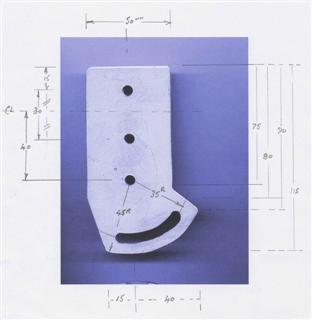
___________4mm Aluminium (or 5mm Birch ply).
___________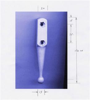
___________1 piece of Beech of 20 X 20 X 150 (130 finish) mm section. Bolt heads interference fit in recessed holes(10mm for 6mm bolts)
___________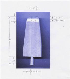
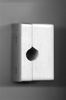
___________Support Up-stand . 13 mm hole is relieved to 2/3 depth on front and sides to allow pivot swing.
EDIT: I have found that it is better not to have this support stand, forming the socket at the base rail level allows the weight of the tool to be more evenly balanced about the pivot point on smaller grinders.See later post
___________
___________Centre Line of Tool to Centre Line of Ball 150mm.
___________
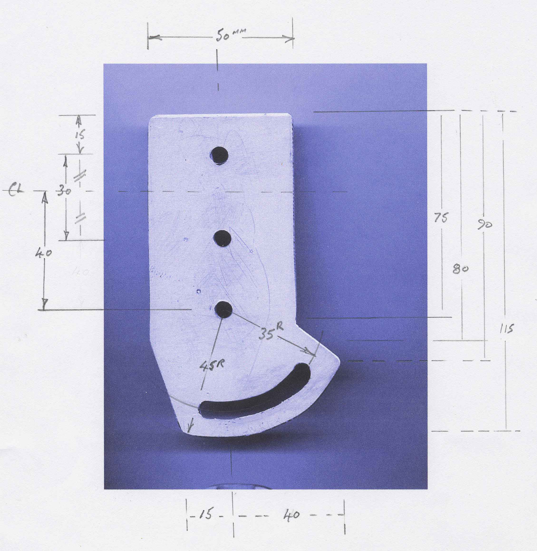
___________Tool Support Clamp, Drilled to suit Tools, 12.7mm (1/2") is good for 13mm tools, a smaller width Vee Cut would allow wider tool shank size variation.
Some points on construction to note:
The dimensions are not super critical as the final angle of grind is dependant on user setup, the distance between the Pivot Rod Ball Centre and the Gouge Clamp Hole Centre and the Height of the Support Up-stand suit a 6" grinder, I see no reason why they are not viable with an 8" unit due to the adjustments available. The commercial equivalent appears to cover both grinder centre heights.
___________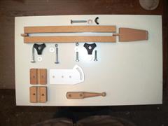
___________Most of the Bits.
___________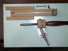
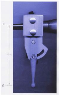
___________Ready to Go.
___________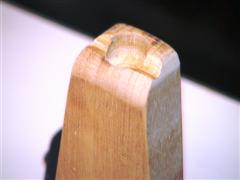
___________Socket detail.
___________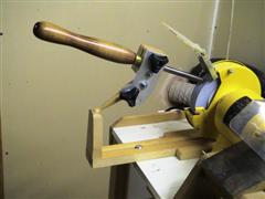
___________In use, Adjust Support Distance from Grinding Wheel and Pivot Angle to suit profile (or desired profile) of tool.
1. To make an alternate style Fingernail & Bowl Gouge grinding Jig. (see previous limited adjustment version)
Reasons:
1. Need of an additional Jig to cover more diverse profiles, and explore different techniques.
Design criteria:
1. To provide the equivalent function of the commercial units.
2. To do it with components/materials readily available in a wood shop.
Materials used:
1. 2 pieces of Beech of 20 X 20 X 300 mm section. Main Rails
2. 2 pieces of Beech of 20 X 20 X 150 mm section. Bench Guides
3. 1 piece of Beech of 45 X 55 X 20 mm section. Tool Clamp
4. 1 piece of Beech of 45 X 55 X 10 mm section. Tool Clamp
5. 1 piece of Beech of 20 X 20 X 150(130 finish) mm section. Adjustable Pivot
6. 1 piece of Beech of 20 X 46 X 120 mm Support Up-stand. See later note.
7. 115 X 68 X 4 mm metal plate. (5mm Birch Ply as alternate)
8. Coach Bolts, Hex headed Bolts, Wing Nuts, Washers and Nuts to suit (6mm.)
Click on images for Larger Files (390 K each) for some reason the drawings do not display well but should be printable to near scale if first saved to local machine (dependant on users software of course).
___________
___________4mm Aluminium (or 5mm Birch ply).
___________
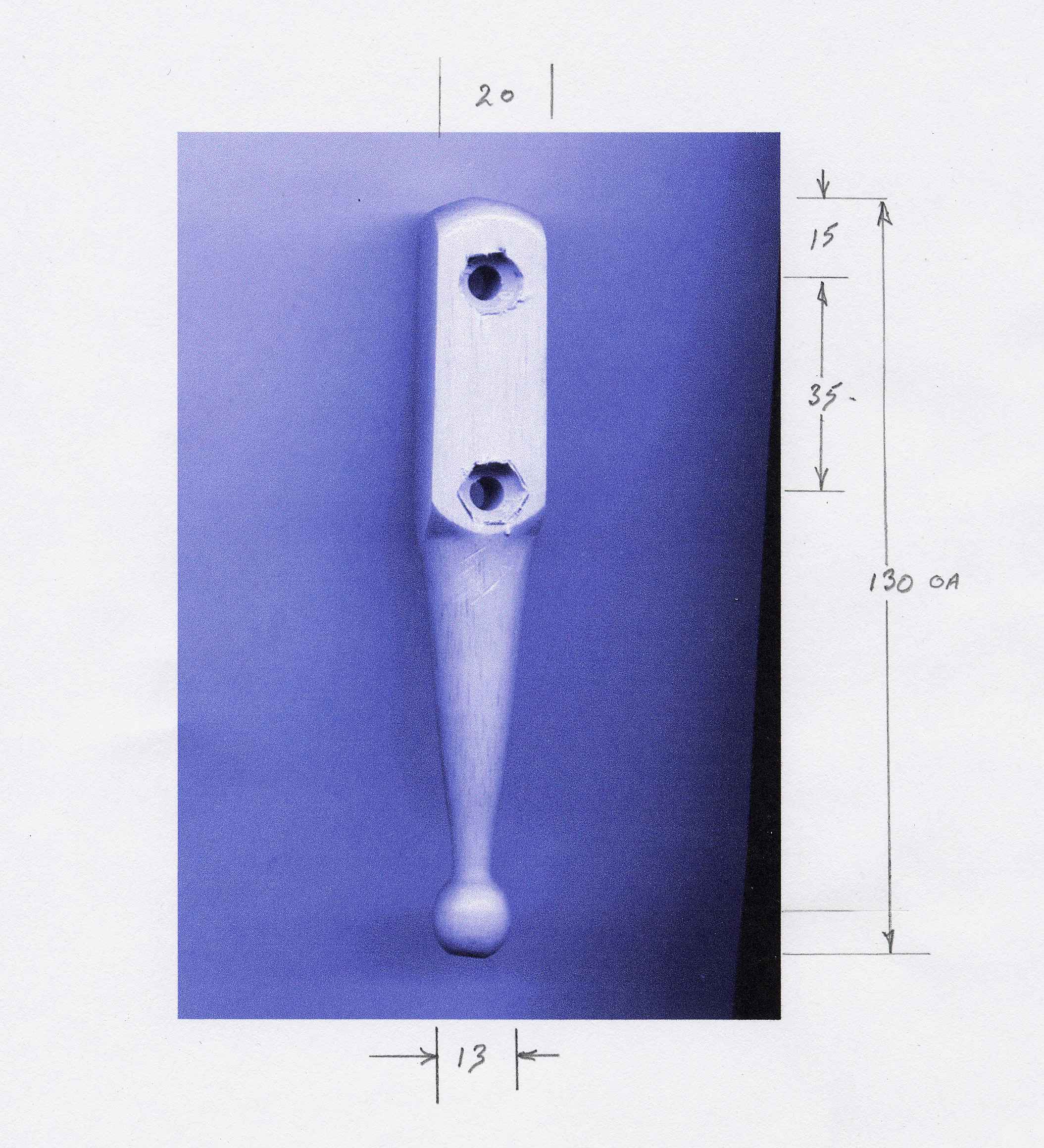
___________1 piece of Beech of 20 X 20 X 150 (130 finish) mm section. Bolt heads interference fit in recessed holes(10mm for 6mm bolts)
___________
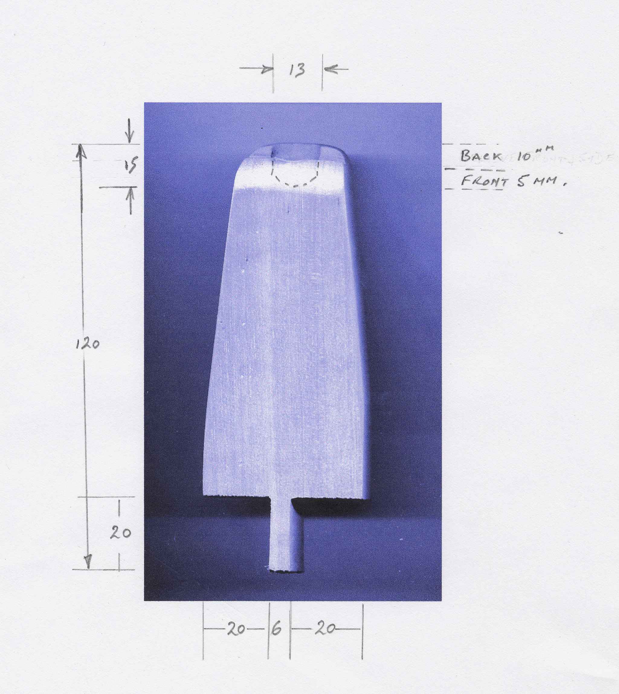
___________Support Up-stand . 13 mm hole is relieved to 2/3 depth on front and sides to allow pivot swing.
EDIT: I have found that it is better not to have this support stand, forming the socket at the base rail level allows the weight of the tool to be more evenly balanced about the pivot point on smaller grinders.See later post
___________
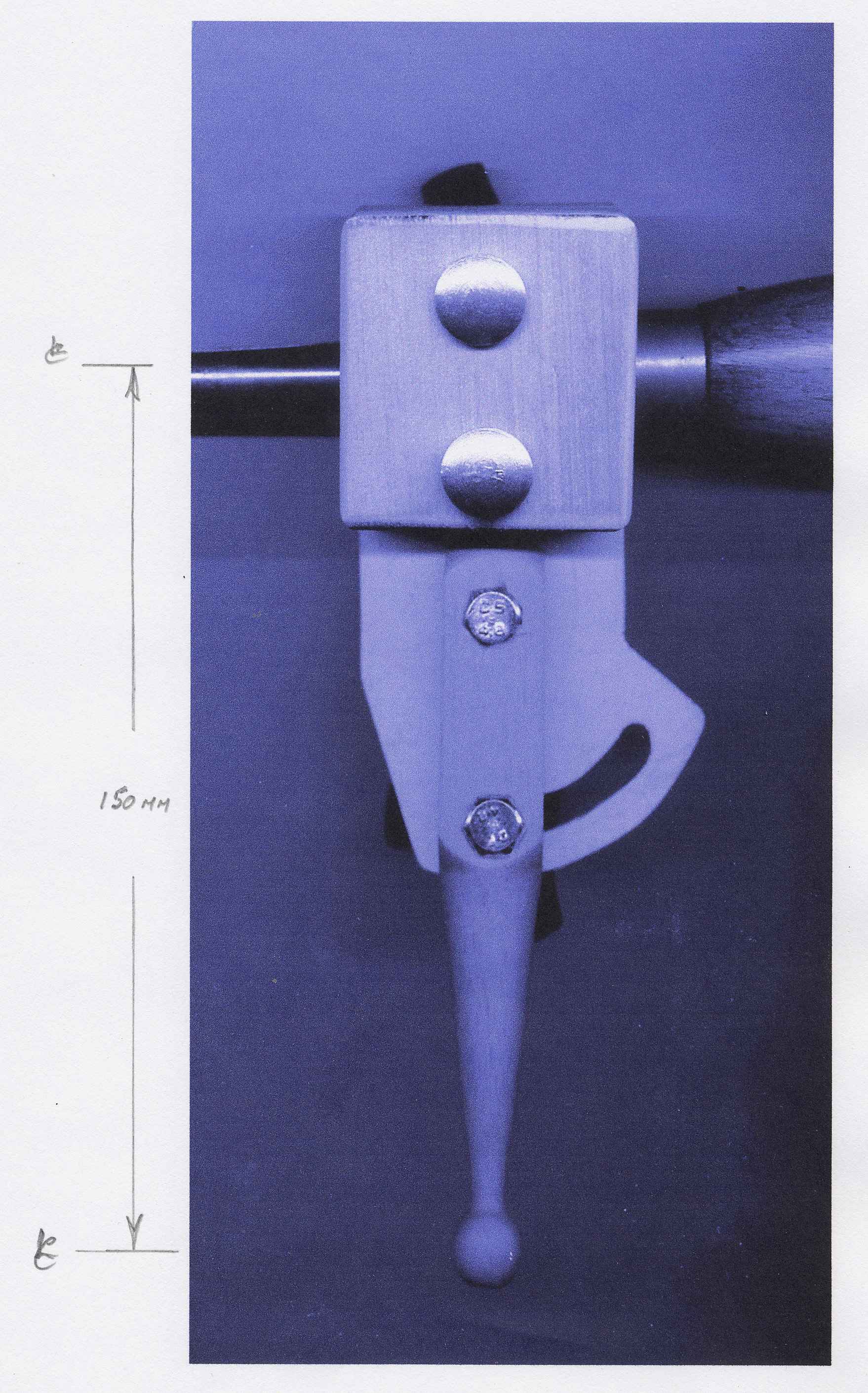
___________Centre Line of Tool to Centre Line of Ball 150mm.
___________

___________Tool Support Clamp, Drilled to suit Tools, 12.7mm (1/2") is good for 13mm tools, a smaller width Vee Cut would allow wider tool shank size variation.
Some points on construction to note:
The dimensions are not super critical as the final angle of grind is dependant on user setup, the distance between the Pivot Rod Ball Centre and the Gouge Clamp Hole Centre and the Height of the Support Up-stand suit a 6" grinder, I see no reason why they are not viable with an 8" unit due to the adjustments available. The commercial equivalent appears to cover both grinder centre heights.
___________
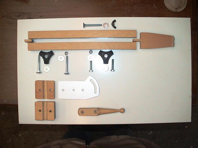
___________Most of the Bits.
___________

___________Ready to Go.
___________
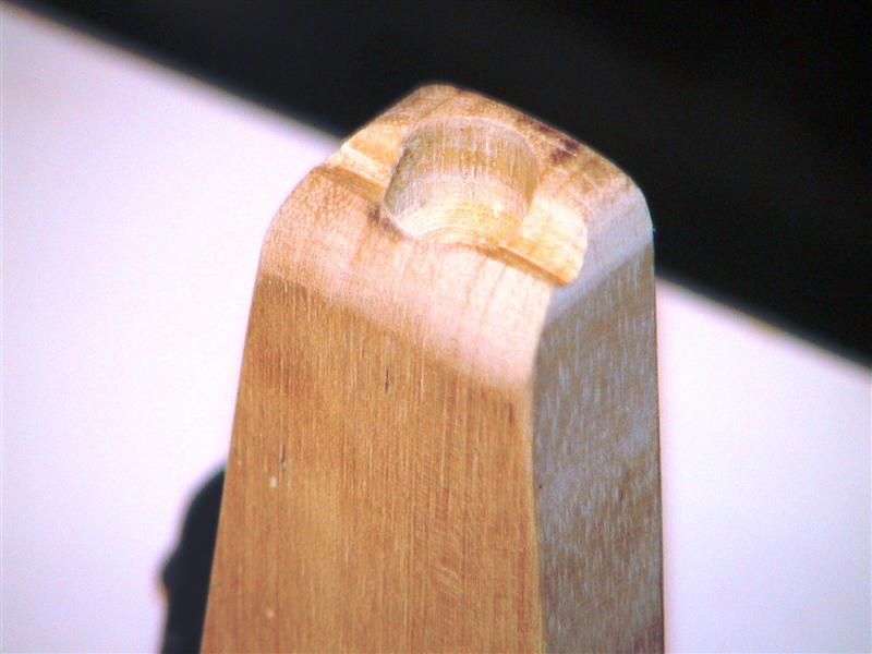
___________Socket detail.
___________

___________In use, Adjust Support Distance from Grinding Wheel and Pivot Angle to suit profile (or desired profile) of tool.
")