Graduation Jewellery Box - WIP

UKworkshop.co.uk

Help Support UKworkshop.co.uk:

This site may earn a commission from merchant affiliate links, including eBay, Amazon, and others.

jkljosh

Established Member
Joined
16 Jan 2009
Messages
80
Reaction score
0
Location
Nr Caernarfon, Gwynedd
Hi Folks

In a fit of spontaneity I rashly offered to make a jewellery box to house some pretty baubles a friend had purchased for her daughter's graduation in June. Having not posted anything for a while, I thought it might be fun to put together another WIP for everyone's entertainment. I've been working on the box off an on for a couple of weeks and graduation is looming very large on the horizon, so I thought I'd spread my resources and start to commit some of the effort to electronic paper before I forget what I've been up to. Perhaps not the wisest of strategies, as I still have a heap of stuff to complete on the box, but hey, a change is as good as a rest my dear Mother used to tell me. So here goes.........

The brief was very loose - a box with some storage trays. Further probing elicited some more detail on the bones - 4 trays one for rings, one with lots of sections, one for necklaces, another for odds and sods. I suggested a void beneath the trays for bigger bits or important documents, and thus the interior started to take shape. As far as box design went, the best I could get out of my friend was clean lines, but somethi
ng a bit different perhaps...... No real help there then!

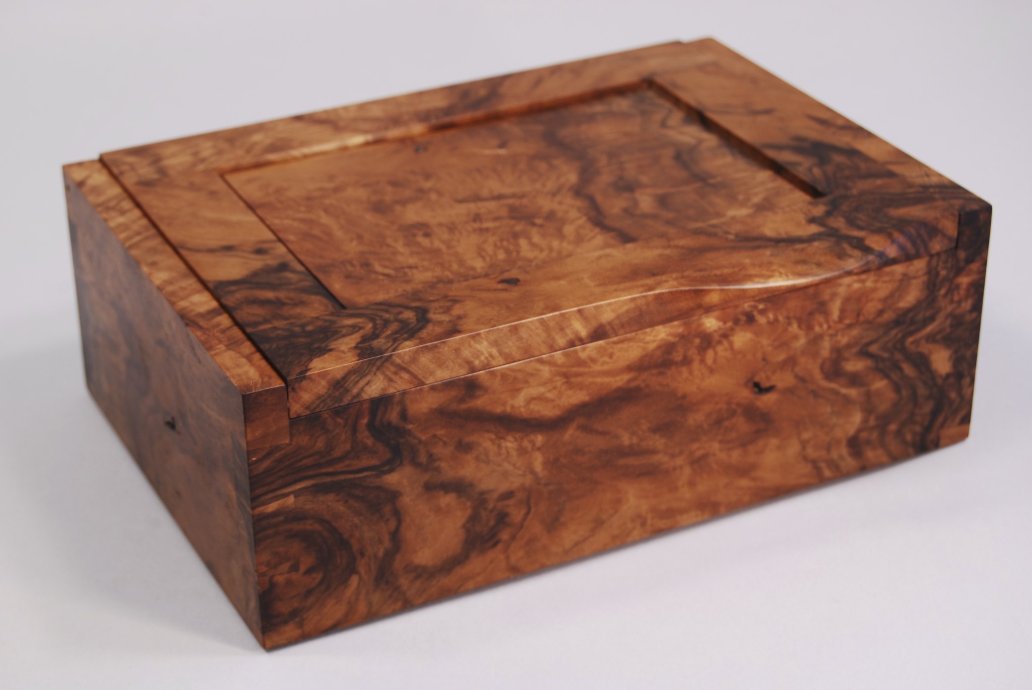
I decided to go for something relatively delicate in section, oddly spaced dovetails and an inset lid pivoting between the sides. So far so good.
Image00010 (Small).jpg


Not the best of images but hopefully all will become plain as the post goes on.

I decided on using some cherry for the body of the box with a cedar base.
Image00014.jpg

and an odd offcut of something interestingly figured for the trays.

It all needed resawing to get the thickness down to something close to my planned 11mm sides.

The cherry needed resawing
Image00002 (Small).jpg


as did the cedar and wood for the tray
Image00003.jpg


Time is against me - I'd forgotten how long it takes to resize and upload photos. More to follow over the weekend!
 

Attachments

  • Image00010 (Small).jpg
    Image00010 (Small).jpg
    113.8 KB · Views: 1,634
  • Image00014.jpg
    Image00014.jpg
    187.1 KB · Views: 1,634
  • Image00002 (Small).jpg
    Image00002 (Small).jpg
    133.2 KB · Views: 1,634
  • Image00003.jpg
    Image00003.jpg
    190.9 KB · Views: 1,634
If you use a camera rather than a phone, you can program the picture size in, so you don't have to do it individually.
I had promised myself to make one for my daughter's graduation, but a couple of months in hospital in the last few months put the kibosh on it. :(
 
Nice. My favourite occupation when I've got the time is to make little boxes. Really looking forward to the progress on this one :)

Paul
 
I'm very impressed with the plans. I make more boxes than anything else but have the bad habit of designing / making them on the hoof which means that not only do they come out completely differently to what I envisaged (not always a bad thing) but I frequently spend a lot longer making them as I'm only thinking one or two steps ahead - rather than knowing how I'm going to do the whole project. I've now invested in a drawing board similar to yours to try and force myself to plan the whole project.
I'll be very interested to see the WIP pictures but if it's of any use, I probably spend as much time sawing, resawing, planing and thicknessing as do in actually making my boxes.
 
Thanks for immediate feeback guys - apologies for lack of updates/response, but I've been concentrating on actually finishing the box in advance of next week's deadline, rather than writing about it! Good progress over the weekend means that I can relax a bit this week and so I thought I'd play catch up here. Thanks Phil, I'll bear that in mind for my next WIP - unfortunately I've captured pretty much all the images on my phone so far - must dig out my old compact digital camera for use in the workshop. I know what you mean about designing/making on the hoof - I do that for some things that I make for myself (I'll have to put up a thread on the oak cabinet I made to cover ugly electrics/consumer unit that I build in exactly that fashion) - but when working on things for others, I find it safer to be a little more ordered. The resawing went pretty smoothly and didn't take as long as I had expected - previous attempts had not been so successful. However, due to the limitations of my planer thicknesser I couldn't get the resultant small boards thin enough for my rather "delicate" intentions so I ended up making a jig to reduce the gap sufficiently to get them down close to 11mm and 6mm respectively. I'm not sure whether that took as much time as it would have been to do it by hand to be honest......
Image00089.jpg

Image00009 (Small).jpg

However, I've got it for use in the future now, so I guess it falls into the bucket of jig making costs that will pay dividends in future projects. Either way, success was achieved and a set of reasonably evenly-thicknessed pieces resulted, although there was a slight issue with them flexing when only under 1 feed roller on the P/T causing each of the components to have a thin element where the wood moved up into the cutter. I reasoned that I could take that out with a sharp plane, although in future I will probably make an over allowance in length of stock so that such problems can be resolved by cutting that off as waste stock.
Image00011 (Small).jpg

Thence it was straight to my newly acquired 2nd hand woodrat for the asymmetric dovetails on the main body of the box - sides first.....
Image00017.jpg

I have used a woodrat before, and wasn't happy with the accuracy when cutting batches of components simultaneously, so have adopted the approach suggested here - http://www.aldel.co.uk/dovetails.htm - I find with care you end up with very accurate result albeit more time consuming than processing in batches. More photos of that later when it comes to the trays....
Initial test dry fit suggested that my approach was the right one for me.
20170517_131742 (Small).jpg

My hound is looking sad and demanding a walk - more to follow later
20170520_175343 (Small).jpg
 

Attachments

  • Image00089.jpg
    Image00089.jpg
    187.9 KB · Views: 1,455
  • Image00009 (Small).jpg
    Image00009 (Small).jpg
    108.3 KB · Views: 1,455
  • Image00011 (Small).jpg
    Image00011 (Small).jpg
    129.6 KB · Views: 1,455
  • Image00017.jpg
    Image00017.jpg
    230.2 KB · Views: 1,455
  • 20170520_175343 (Small).jpg
    20170520_175343 (Small).jpg
    125 KB · Views: 1,455
  • 20170517_131742 (Small).jpg
    20170517_131742 (Small).jpg
    110.7 KB · Views: 1,455
Hound excercised, dinner cooked - refreshed and ready for next instalment. I had decided on a cedar base for the box as I think, as with drawers, it is lovely to open a box and have that lovely cedar aroma assail your nostrils. Being a bluff old traditionalist I opted to have the base floating in a rebate in the box sides to allow for any differential movement between the two different species - yes I know it's unlikely on such a small item and with well seasoned wood, but....., like I said I'm a bluff old traditionalist.

Trusty triton router table to the fore
Image00020.jpg

to put a step on the base
Image00022.jpg

Easily enough done and then stress levels rose as I approached my snugly-dovetailed box sides for the associated rebate. I dunno about the rest of you, but I'm a great believer in test pieces to get set ups right.
Image00024 (Small).jpg

The front and back could simply be routed along their whole length, but the sides needed stopped rebates to maintain the integrity of the ends of the dovetails. A couple of clamped blocks did the trick - one day I'll get round to making a fancy jig for the router table to make this simpler.
Image00030 (Small).jpg

Small spot of fettling with some nicely honed chisels to square up the ends of the stopped rebates....
Image00034 (Small).jpg

Hey presto
Image00035 (Small).jpg

Overall a successful outcome.
Image00032 (Small).jpg
 

Attachments

  • Image00020.jpg
    Image00020.jpg
    214 KB · Views: 1,434
  • Image00022.jpg
    Image00022.jpg
    240.3 KB · Views: 1,434
  • Image00024 (Small).jpg
    Image00024 (Small).jpg
    120.4 KB · Views: 1,434
  • Image00032 (Small).jpg
    Image00032 (Small).jpg
    114.4 KB · Views: 1,434
  • Image00034 (Small).jpg
    Image00034 (Small).jpg
    125.8 KB · Views: 1,434
  • Image00035 (Small).jpg
    Image00035 (Small).jpg
    114.1 KB · Views: 1,434
  • Image00030 (Small).jpg
    Image00030 (Small).jpg
    119.9 KB · Views: 1,434
The lid then needed to be fitted which was going to require some accurate work to get the placement of the homemade pivot hinges spot on. As I said in the introduction, I couldn't source any small enough decent quality butt hinges so had decided to go down the path of making my own hinges. These help with the clean lines on the outside of the box that I wanted to achieve, but did give me a bit of a headache over how to get the relevant holes accurately in place in both the edge of the lid and the back corner of the sides. As you might be able to spot from the earlier drawings, the box sides extend above the lid, so it wasn't quite as simple as it might have been had I made the sides flush with the top.

But first I needed to drill the end of the lid to take the brass dowel pin. It was then I realised that my earlier issues with the planer had left me rather less material to play with than my planned 11mm thickness for the sides - I was down to 9mm!! Ho hum, all I needed to do was accurately centre a 6mm hole in the edge of the board in exactly the same relative position to ensure that the lid would swing square once fixed between the two sides. Marking out accurately seemed the best place to start.....
Image00039.jpg

Back to the trusty Woodrat, fitted with a Wealden dowel hole spiral bit fitted this time
Image00045.jpg

Phew!!
Image00041.jpg

I love my Woodrat :D
And so to make the brass dowel pin and associated socket. I did things this way round as I wanted to make the pins long enough to provide a 1mm gap on either side of the lid - easier to adjust the pin length on the model making lathe to achieve that, rather than trying to do the fine tuning when drilling the hole - lower opportunity cost of a mistake in brass. Also it meant that I could machine the dowel to be an interference fit in the hole, thereby obviating the need for epoxy or other glue to hold it accurately in place - the box sides would do that once everything was glued up. Brass socket needed in the sides to stop the pin wearing an eccentric hole in the wood over time in use. Confused? All will become clear :wink:
Time to break out my dear departed Dad's beautiful Unimat SL - they don't make 'em like this any more.
Image00042 (Small).jpg

Some drilling for the sockets and a spot of paring (or what ever the correct metal working term is) for the pins.
Image00048.jpg

and soon enough we have the required components (albeit without the parting off nibs removed from the components)
Image00050.jpg

And so to drilling the sides for the sockets...... - tricky.......
At the design stage I had spotted that in order for this hinging mechanism to work, I would need clearance under the back of the lid to allow the bottom corner of the lid edge to swing past the top edge of the back - clear as mud? Here's a picture to help with the back of the lid supported on a 2mm spacer.
Image00051.jpg

I had even allowed for that 2mm difference by making the depth of the front of the box bigger than the back to ensure that the lid would lie flat as in the image above.
All I needed to do was get the hole for the socket in the right place on the sides - far enough in from the back to ensure everything would be flush, and low enough down to ensure the lid would be flat.
Image00052.jpg

Any one spotted my deliberate mistake yet?......
No?........
Me neither before I progressed to the pillar drill, although you'll note my ongoing enthusiasm for test pieces - this one used to adjust the back fence position so that the height of the hole from the top of the sides was consistent on both left and right components.
Image00053.jpg

Still not spotted the deliberate mistake?
Me neither, so of course I drilled the other side too......
Image00056.jpg

And with that I will bid you adieu for now. I wonder how many of you will spot what I did wrong before I reveal all in the next installment. Don't stay up too late pondering it - only a complete clutz would make a school boy error like this one - so I am quite happy to lay claim this June's Workshop Donkey of the Month Award.
 

Attachments

  • Image00045.jpg
    Image00045.jpg
    191.6 KB · Views: 1,413
  • Image00042 (Small).jpg
    Image00042 (Small).jpg
    159 KB · Views: 1,413
  • Image00048.jpg
    Image00048.jpg
    232.9 KB · Views: 1,413
  • Image00050.jpg
    Image00050.jpg
    209.9 KB · Views: 1,413
  • Image00051.jpg
    Image00051.jpg
    163.4 KB · Views: 1,413
  • Image00052.jpg
    Image00052.jpg
    216.6 KB · Views: 1,413
  • Image00053.jpg
    Image00053.jpg
    238.4 KB · Views: 1,413
  • Image00056.jpg
    Image00056.jpg
    202.3 KB · Views: 1,413
  • Image00041.jpg
    Image00041.jpg
    117.4 KB · Views: 1,413
  • Image00039.jpg
    Image00039.jpg
    200.2 KB · Views: 1,413
You will need to round over the inside corner of the lid to allow the lid open.

Pete
 
Good point well made Pete, although not the error I was looking for - I had anticipated some kind of "easing" activity on the inside corner of the lid - whether that be a small bevel or as you suggested rounding off. As to the my mistake let the story unfold.

And so the gods of measure twice and cut once looked on in amusement as he struggled with making sure the holes in the sides were in exactly the right place - marking out carefully executed on the corner, fences deftly positioned, test pieces drilled.......all to assure himself that the holes would be spot on. And so they were. The trouble is what one must not forget when working on asymmetric boxes is that the sides have a front and a back. :shock: The gods chuckled mercilessly at his carelessness.........

Not entirely sure how I managed to mix things up but suspect that it was an oversight based on being so preoccupied with getting the holes in the right position on the side. As you can see in the image of the marking out the C and D are clearly visible as part of my coding to ensure components stayed in the correct orientation, it is just they were the designations of the front of the box not the back!! In mitigation, I suspect I might have done the intellectually lazy thing of looking at the front and back pieces and thinking that of course the narrower one is the front, and the taller one the back - as that is the natural way of things: they slope from tall back to short front. I was also really worried about drilling the bottom corner of the side and not the top corner! I only realised my error when I reassembled the box and lay the lid in place at which point it became glaringly apparent that the tall long piece was on the hole side and not the other. :oops:

The censor prevents me from recounting what was said in my workshop at that moment! :x

I've made similar but different mistakes in the past and realise that the best way to deal with them is to step away from things and not try to fix them immediately when judgement might be clouded by the angry red mist that inevitably descends. Work was suspended for the day and thence an overnight contemplation of options pouring over the drawings while enjoying a glass or two of fine red.

As they do, the next day dawned and I went back into the fray. I decided to do nothing! Yes the lid would slope slightly from front to back, but I reasoned if it really disturbed me then I could always taper the top of the sides to match once everything was glued up. Although the hinges were on the "wrong" side, they did exactly what I had planned where the 1mm gap between the lid and sides was concerned:
Image00074.jpg


And so I moved on - final tidying up the components including cleaning up the edges and sorting the clearance chamfer on the bottom of the back edge of the lid (Well spotted Pete)
Image00060.jpg

Now the hinges were in place I could address the issue around how to make it easy to open the box. Ideally I wanted the lid to be flush with the front edge, but had left myself the option of having a small lip on the lid over hanging the front - that could run the whole width of the box, or be shaped to provide a handle (in the middle? one on either side?). Design opportunities abound. I find being able to look and feel helps in the design effort at this point and some am happy to experiment to see what works best.
Image00036 (Small).jpg

As it turned out I really wasn't happy with the look of the lid being proud so I planed it to fit flush with the front edge.
Image00062.jpg

It looked much better, but highlighted the need for a handle as it was tricky to open the lid in it's newly flush state.
Something in a strongly contrasting colour seemed appropriate so I rummaged in the offcuts bin for a bit of walnut. More resawing required:
Image00064.jpg

and a bit of effort with a sharp No.4
Image00067 (Small).jpg

Image00065.jpg

A small prototype made out of an old blind slat gave me a sense of proportion
Image00070 (Small).jpg

And some careful marking out for the mortice
Image00071.jpg

followed by even more careful routing on the Woodrat gave me a nicely formed mortice
Image00075.jpg

I hope I am not boring everyone with all this detail, but am never quite sure how much people want in these WIPs. Slightly losing the will to live here though as putting together the WIP seems to be taking as long as making the damned box. I'm gonna take a break having hit my 10 images limit for a single post. Maybe more later!
 

Attachments

  • Image00060.jpg
    Image00060.jpg
    217.7 KB · Views: 1,365
  • Image00074.jpg
    Image00074.jpg
    107.4 KB · Views: 1,365
  • Image00036 (Small).jpg
    Image00036 (Small).jpg
    102.2 KB · Views: 1,365
  • Image00062.jpg
    Image00062.jpg
    200.5 KB · Views: 1,365
  • Image00064.jpg
    Image00064.jpg
    209.7 KB · Views: 1,365
  • Image00067 (Small).jpg
    Image00067 (Small).jpg
    146.7 KB · Views: 1,365
  • Image00065.jpg
    Image00065.jpg
    249.9 KB · Views: 1,365
  • Image00070 (Small).jpg
    Image00070 (Small).jpg
    96.4 KB · Views: 1,365
  • Image00071.jpg
    Image00071.jpg
    234.5 KB · Views: 1,365
  • Image00075.jpg
    Image00075.jpg
    209.2 KB · Views: 1,365
Bored?! I'm savouring every word and picture. This is exactly the sort of work I would be doing if I had a workshop, which I am currently building but will be a few months before it's up and running. I'm completely in my element making small boxes and missing it like mad since we moved up here to Scotland 2 years ago. So your posts are a kind of surrogate for me, although I'm not sure I could emulate your fine workmanship. And yes, I've made exactly the same mistake myself :roll:

Keep it coming please -I'm loving it!

Paul
 
Here's one of mine, also similar to yours. Turkish Walnut, dovetailed, handle carved from the solid on the front rail of the top panel - Rob

 
Hi Guys and Gals, finishing this WIP will be the end of me!! Busy day today, so I find myself settling down to type way past my bedtime, but if I don't chip away at it, it is just not going to happen. Thanks for all the positive feedback/comments, glad you are enjoying my ramblings. Lovely to see your work Pete/Rob and particularly liked the differing approaches adopted on the handles, as will shortly be revealed mine is another variation on the theme of how to attach a handle to a box lid! I have been watching your workshop build thread with interest Paul, hope you can get back to some smaller scale creativity soonest. I know how much I have missed it in recent years. Any how enough wittering "on with the WIP" I hear you cry.

I quite like getting to grips with small and fiddly bits and bobs so playing with the walnut handle was an enjoyable distraction. A spot of work on the router established the shoulders of the tenon which was then cut to length with my japenese pull saw. I don't usually use this for anything other than the finest work, but am starting to come round to the idea of perhaps expanding its repertoire on larger dovetails - the really fine kerf and exceptional sharpness do make these things a joy to use. That said my earlier observations about bluff old traditionalist still pertain and so I may take time to move away from my trusty LN fine toothed dovetail saw. Pictures required to keep you all interested
Image00076.jpg

Image00077.jpg

Low angle block plane provided the means of generating a gentle curve on the handle
Image00078 (Small).jpg

and thence some fine tuning of the tenon with a medium shoulder plane gave me the desired result - small but elegantly formed (IMHO) walnut handle.
Image00081.jpg

And so to the internals. As I think I mentioned in the intro the box was to have 4 trays and a void space at the bottom, the latter being created by the fitting of some 20mm slips in the base of the box. Out trusty, if somewhat mildewed (following my move to N Wales and it being left in an uninsulated and rather damp and drafty workshop for nigh on 2 years) mitre shooting board and my low angled jack plane.
Image00082.jpg

A bit of fettling left me with 4 roughly fitted slips - the box wasn't glued up at this stage as I needed to pre-finish the insides and lid before glue up, so I was relying on it being pulled together by clamps. I therefore didn't waste too much time fine tuning the slips, as I knew that they would have to be revisited once everything was squeezed up tight.
Image00086 (Small).jpg

And so to the trays. I don't know about the rest of you, but I am hopeless at keeping track of lots of components, particularly when they are all similar, so trays are always something of a nightmare for me. Being paranoid I tend to mark everything uniquely - using alpha numerics - to keep track of which corner is which on which tray: thus A1-B1, B1-C1, C1-D1, D1-A1 for each element of tray 1, A2-B2, B2-C2 etc for tray 2. I know some who use coloured stickers to achieve the same, but I find stickers come off, and I am also colour blind, so complete bedlam would ensue if I adopted that approach. Anyway - lots of components to keep track of, size, and shape.......
Image00093.jpg

Once cut to length, I then adjusted the width of each tray's components by planning them on edge together - I find doing this against a stop (rather than trying to hold them in a vice), a good way to get consistency as having them balanced on edge forces me to go gently with the plane pressure.
Image00094 (Small).jpg

I then used a small shooting board to trim the sides to length.
Image00097.jpg

As you can see it is a very snug fit as I like to clean up the trays once they are glued up, taking a fraction of their length in an attempt to get them to "piston fit" into the box. I'm not always successful, but it is very satisfying when it happens. Practice will make perfect!!

Now earlier in the piece I did promise a more detailed expose of how I use the Woodrat for dovetailing following Abel's approach. This I will do, but on another day - it is late, I am close to my image limit for a single post, and most importantly I need my beauty sleep. More to follow........
 

Attachments

  • Image00076.jpg
    Image00076.jpg
    183.3 KB · Views: 964
  • Image00077.jpg
    Image00077.jpg
    187.9 KB · Views: 964
  • Image00078 (Small).jpg
    Image00078 (Small).jpg
    124.3 KB · Views: 964
  • Image00081.jpg
    Image00081.jpg
    249.5 KB · Views: 964
  • Image00082.jpg
    Image00082.jpg
    248 KB · Views: 965
  • Image00086 (Small).jpg
    Image00086 (Small).jpg
    103.5 KB · Views: 965
  • Image00093.jpg
    Image00093.jpg
    205.4 KB · Views: 964
  • Image00094 (Small).jpg
    Image00094 (Small).jpg
    146.3 KB · Views: 964
  • Image00097.jpg
    Image00097.jpg
    233.7 KB · Views: 964
It's been a whole week! Did you make the deadline? Was it well received? Can I stand the suspense? Put me out of my misery please - I'm much too old for this stuff!
 
Time flies when you are busy and enjoying yourself. Apologies for the interruption to the documentation of progress - I needed to get the box finished, rather than writing about making it! Apologies for the stress caused Paul - you will be happy to learn that I did indeed make the deadline and the box was delivered after the graduation ceremony in Dundee last Thursday. I have been busy since and not got close to the computer, but now am committed to getting the last phases of the build documented, so that I can get on with other things.

Soooooooo, making trays using the woodrat for the dovetails. As I said earlier in the post I don't like using the woodrat in batch mode - I have not yet found a system that gives me consistently sufficiently accurate results, although I might do some more experimentation on that in due course. The dovetails themselves are straight forward and just a question of sorting out the spacing and setting the cutter depth right. This is the quick bit and generates a set of tailed sides pretty quickly.
Image00099 (Small).jpg

The associated pins are then marked out corner by corner using the Rat to hold the relevant pieces while fine lines are scribed
Image00100.jpg

Image00102.jpg

I forgot to take photos of the top plate arrangements, but these are simply the guide scrolls being set to the relevant angle for the tails to guide the router plate at the correct angle. It is then just a case of hand routing the waste between the pins. The lightly scribed lines make it easy to creep up to the line - sometimes without even adjusting the carriage - merely "squeezing" the router up against the scolls to take of the tiniest amount. Well placed bright lights help with cutting right to the line.
Image00103.jpg

Proof of the pudding is in the eating .......these are the resulting joints straight off the router
Image00108.jpg

Image00107.jpg

In relatively short order all 4 trays were taking shape.
Image00111 (Small).jpg

Tray bases were 1.5mm birch ply and needed rebates cutting in the tray sides, and so back to the router table - in this case my smaller one for delicate work. Nothing sophisticated, just a batten for a fence set up to provide the required inset for the base, and some stops to make sure I didn't route all the way through the pins.
Image00115.jpg

As ever a test piece was required.....
Image00113 (Small).jpg

Leads to successful outcomes (for the most part!)
Image00116.jpg
 

Attachments

  • Image00099 (Small).jpg
    Image00099 (Small).jpg
    168.2 KB · Views: 887
  • Image00100.jpg
    Image00100.jpg
    160.9 KB · Views: 887
  • Image00102.jpg
    Image00102.jpg
    133.7 KB · Views: 887
  • Image00103.jpg
    Image00103.jpg
    215.1 KB · Views: 887
  • Image00108.jpg
    Image00108.jpg
    114.2 KB · Views: 887
  • Image00107.jpg
    Image00107.jpg
    186.3 KB · Views: 887
  • Image00111 (Small).jpg
    Image00111 (Small).jpg
    136.5 KB · Views: 887
  • Image00115.jpg
    Image00115.jpg
    193.1 KB · Views: 887
  • Image00113 (Small).jpg
    Image00113 (Small).jpg
    95.5 KB · Views: 887
  • Image00116.jpg
    Image00116.jpg
    252.6 KB · Views: 887
I roughly cut the ply to size before trimming it square on the table saw. As my saw does not readily allow me to use a zero clearance throat plate I needed to improvise a zero clearance system to stop tear out on the back of the ply. Simply a hunk of 18mm MDF strapped to the sliding table and then run through the blade. Oak stop block set to give the required size and bob is your uncle.
Image00121 (Small).jpg

Image00117 (Small).jpg

Image00119 (Small).jpg

Tray dividers were going to be made from 2mm constructional veneers, cut to length on the table saw and thence trimmed to width in pairs on a shooting board.
Image00123.jpg

For the narrow trays I decided to put a small shoulder on the dividers and inset it into a small rebate in the tray side. More messing around with the small router table, using a home made sliding carriage (built to cut finger joints) and some stops to dictate the length of the slots.
Image00124.jpg

Image00126.jpg

and yes that is another test piece you see being butchered as I fine tuned the set up (better that butchered than one of my carefully crafted sides!)
Horizontally divided tray takes shape.......
Image00127.jpg

Image00128.jpg

As did the vertically divided one!
Image00130.jpg
 

Attachments

  • Image00121 (Small).jpg
    Image00121 (Small).jpg
    114.8 KB · Views: 880
  • Image00117 (Small).jpg
    Image00117 (Small).jpg
    109.5 KB · Views: 880
  • Image00119 (Small).jpg
    Image00119 (Small).jpg
    113 KB · Views: 880
  • Image00123.jpg
    Image00123.jpg
    202.3 KB · Views: 880
  • Image00124.jpg
    Image00124.jpg
    160.2 KB · Views: 880
  • Image00126.jpg
    Image00126.jpg
    250.9 KB · Views: 880
  • Image00127.jpg
    Image00127.jpg
    166 KB · Views: 880
  • Image00128.jpg
    Image00128.jpg
    161.9 KB · Views: 880
  • Image00130.jpg
    Image00130.jpg
    182.8 KB · Views: 880
Back
Top